Fundamentals of Flight Control Theory
Laboratory Work №2 - 3
Aircraft Coordinate System Definitions
Brief Theoretical Review
Aircraft Degrees of Freedom and the Equations of motion
To develop the equations governing aircraft motion, we must first understand what paths through space the aircraft is free to follow. These paths are defined as degrees of freedom. If we assume the aircraft is rigid, we find that in inertial, three-dimensional space it has six degrees of freedom: it can move forward, sideways, and down, and rotate about any of the free orthogonal axes. From Newton’s second law governing translational and rotational motion, we can derive two vector equations of motion: one relating the external forces to the aircraft motion and the other relating the external moments to the aircraft motion. Various coordinate systems have been defined which allow the external forces and moments to be easily related. Thus, a basic understanding of these coordinate systems and of the relationships among them is necessary before we can apply Newton’s second law to develop either of the equations of motion.
Aircraft coordinate systems
Inertial
An inertial coordinate system is a non –accelerating, non-rotating reference frame in which Newton’s second law is valid. Therefore, the equations defining the motion of an aircraft must be developed in an inertial coordinate system. However, experience with physical observations can be used to determine whether a particular reference system can properly be assumed to be an inertial coordinate system for the application of Newton’s law to a particular problem. For space dynamics in our solar system, the sun axis system is a sufficient approximation for an inertial system. For aircraft flying in stratosphere, the flat Earth referenced coordinate system is usually a sufficient approximation of an inertial coordinate system.
BODY-FIXED REFERENCE FRAME
The
body-fixed coordinate system is a rotating reference frame with its
origin fixed to the aircraft center of gravity. The axes from an
orthogonal triad defined by the right-hand rule with the x-axis
always pointing through the aircraft’s nose and the y-axis out the
right wing (Fig.1). This coordinate system has unit vectors ![]() .
.
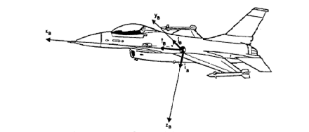
Figure 1 Bode-Fixed Coordinate System
STABILITY –AXIS SYSTEM, Fs
The
stability coordinate system is a rotating reference frame with the
origin located at the aircraft center of gravity. This system is made
up of unit vectors ![]() again forming an orthogonal triad defined by the right-hand rule. The
xs-
and ys
– axes from the plane of motion of the aircraft, with the ys
– axis always aligned with the yb-
axis (Fig.2). The body axes are related to the stability axes through
a single rotation, defined as the angle of attack,
again forming an orthogonal triad defined by the right-hand rule. The
xs-
and ys
– axes from the plane of motion of the aircraft, with the ys
– axis always aligned with the yb-
axis (Fig.2). The body axes are related to the stability axes through
a single rotation, defined as the angle of attack, ![]() ,
about the ys
–axis. Note that under zero sideslip conditions, the xs
– axis is aligned with the flight path vector relative to the
surrounding air mass. The use of stability axes is limited to
symmetric initial flight conditions and small disturbance motions.
,
about the ys
–axis. Note that under zero sideslip conditions, the xs
– axis is aligned with the flight path vector relative to the
surrounding air mass. The use of stability axes is limited to
symmetric initial flight conditions and small disturbance motions.
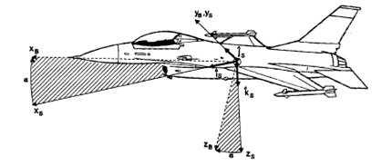
Figure 2 Stability Coordinate System
WIND -AXIS SYSTEM, FW
The wind
coordinate system is a rotating reference frame also with its origin
located at the aircraft center of gravity. The unit vectors ![]() form this right-hand orthogonal system. As was true with stability
coordinate system, the xw
and yw
–axes are located in the aircraft instantaneous plane of motion
(Fig.3). However, the xw
–axis is always aligned with the flight path vector relative to the
surrounding air mass. The wind axis are related to the stability axes
through a single rotation, defined as the angle of sideslip,
form this right-hand orthogonal system. As was true with stability
coordinate system, the xw
and yw
–axes are located in the aircraft instantaneous plane of motion
(Fig.3). However, the xw
–axis is always aligned with the flight path vector relative to the
surrounding air mass. The wind axis are related to the stability axes
through a single rotation, defined as the angle of sideslip, ![]() , about the zs
– axis.
, about the zs
– axis.
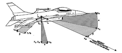
Figure 3 Wind Coordinate System
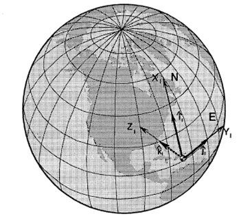
FLAT EARTH REFERENCED
The flat
Earth referenced coordinate system is a “locally” non-rotating
reference frame. This frame is made up of unit vectors ![]() which form an orthogonal triad defined by the right-hand rule. The
system is defined with the zl
– axis aligned with the local gravity vector , toward the center of
the Earth, leaving the xl
and yl
axes to form the local horizontal plane (Fig.4). The xl
– axis is generally aligned with true North placing the yl
– axis toward the Eas. This lends the system to being referred as
the North-East-Down (NED) coordinate sysem. The origin of this system
can be fixed at a particular point on the Earth’s surface, such as
a radar site, or fixed to the aircraft’s center of gravity.
which form an orthogonal triad defined by the right-hand rule. The
system is defined with the zl
– axis aligned with the local gravity vector , toward the center of
the Earth, leaving the xl
and yl
axes to form the local horizontal plane (Fig.4). The xl
– axis is generally aligned with true North placing the yl
– axis toward the Eas. This lends the system to being referred as
the North-East-Down (NED) coordinate sysem. The origin of this system
can be fixed at a particular point on the Earth’s surface, such as
a radar site, or fixed to the aircraft’s center of gravity.