
- •Учреждение образования «высший государственный колледж связи» «чтение и перевод технических текстов по специальности ткс»
- •Часть I
- •Введение
- •Unit 1 (17) Antennas
- •17.1 Types of antennas
- •17.1.1 Antennas used in communications
- •17.2 Basic properties
- •17.3 Generic antenna types
- •17.3.1 Radiation from apertures
- •1 Learn the words & word combinations:
- •2 Read & translate the text (orally) 17.1 – 17.3.2:
- •5 Answer the questions:
- •17.3.2 Radiation from small antennas
- •17.3.3 Radiation from arrays
- •17.4 Specific antenna types
- •17.4.1 Prime focus symmetric reflector antennas
- •17.4.1.1 Parabolic reflectors
- •17.4.1.2 Aperture fields and radiation patterns
- •17.4.1.3 Gain of reflector antennas
- •1Learn the words & word combinations:
- •2 Read & translate the text (orally) 17.3.2 – 17.4.1:
- •5 Answer the questions:
- •17.4.2 Dual symmetric reflector antennas
- •17.4.3 Offset reflectors
- •17.4.4 Horn feeds for reflector antennas
- •17.4.4.1 Rectangular or square horns
- •17.4.4.2 Small conical horns
- •17.4.4.3 Multi-mode conical horns
- •17.4.4.4 Conical corrugated horns
- •17.4.4.5 Array feeds
- •1 Learn the words & word combinations:
- •2 Read & translate the text (orally) 17.4.2 – 17.4.4:
- •5 Answer the questions:
- •17.5 Antennas used in communication systems
- •17.5.1 Microwave line of sight radio
- •17.5.2 Earth station antennas
- •1 Learn the words & word combinations:
- •2 Read & translate the text (orally) 17.5.1 – 17.5.2:
- •5Answer the questions:
- •17.5.3 Satellite antennas
- •17.5.3.1 Telemetry, tracking and command (tt&c)
- •17.5.3.2 Spot beams
- •17.5.3.3 Multiple beams
- •17.5.3.4 Shaped beams
- •17.5.4 Vhf and uhf communications
- •17.5.5 Hf communications
- •1 Write out the words and word combinations which are still unknown to you and learn them. Unit 2 (20) Frequency division multiplexing
- •20.1 Fdm principles
- •20.2 History
- •20.3 Fdm hierarchy
- •20.3.1 General considerations
- •20.3.2 Channel bandwidth
- •20.3.3 Group and supergroup
- •20.3.4 Higher order translation
- •20.3.4.1 15 Supergroup assemblies
- •20.3.4.2 Mastergroup
- •20.3.4.3 Bell system
- •1 Learn the words & word combinations:
- •2 Read & translate the text (orally) 20.1 – 20.3.4:
- •4Find English equivalents:
- •5 Answer the questions:
- •20.4 Frequency translation
- •20.4.1 Ring bridge modulator/demodulator design considerations
- •20.4.1.1 Carrier compression.
- •20.4.1.2 Carrier and signal suppression
- •20.5 Carriers
- •20.5.1 Carrier frequency accuracy
- •20.5.2 Carrier purity
- •20.5.3 Carrier level
- •20.6 Pilots
- •20.6.1 Translation equipment pilots
- •20.6.1.1 Use of reference pilots for automatic gain control
- •20.6.2 Line equipment pilots
- •20.6.2.1 Regulation pilots
- •20.6.2.2 Frequency comparison pilots
- •1 Learn the words & word combinations:
- •2 Read & translate the text (orally) 20.4 – 20.6
- •5. Answer the questions:
- •20.7 Noise contributions
- •20.7.1 Definitions
- •20.7.2 Psophometric weighting
- •20.7.3 Thermal noise
- •20.7.4 Noise due to unlinearity
- •20.7.4.1 Single channel load
- •20.7.4.2 Multichannel load
- •20.7.4.3 Unlinearily characterisation
- •20.7.4.4 Determination ofunlinearity noise from a multichannel load
- •20.7.4.5 Approximate value for the weighted intermodulation noise contribution
- •20.7.4.6 Weighted noise power in pWOp
- •20.7.4.7 Determination of unlinearity noise using spectral densities
- •1 Learn the words & word combinations:
- •2 Read & translation the text (orally) 20.7:
- •5 Answer the questions:
- •20.8 Measurement of noise contributions
- •20.9 Overload
- •20.9.1 Overload measurement.
- •20.9.1.1 Harmonic/intermodulation products
- •20.9.1.2 Gain change
- •20.10 Hypothetical reference system
- •20.10.1 Noise contributions
- •20.10.2 Line sections
- •1 Learn the words & word combinations:
- •2 Read & translate the text (orally) 20.8 -20.10:
- •5 Answer the questions:
- •20.11 Companding
- •20.11.1 Compander characteristics
- •20.11.2 Multichannel load increase
- •20.11.3 Compandor noise advantage
- •20.13 Transmultiplexers
- •20.13.1 Synchronisation
- •20.13.2 Pcm alarms
- •20.14 Repeatered cable line equipment
- •20.14.1 Pre-Emphasis
- •20.14.2 Thermal noise
- •20.14.3 Regulation
- •20.14.3.1 Regulation range
- •20.14.4 Power feeding
- •Translate the text 20.11 – 20.14.4
- •Translate in written form point 20.13 “Transmultiplexers”
- •«Чтение и перевод технических текстов по специальности ткс»
- •Часть I
2 Read & translate the text (orally) 20.1 – 20.3.4:
3 Find Russian equivalents:
|
|
|
|
|
|
|
|
|
|
|
|
|
|
4Find English equivalents:
|
|
|
|
|
|
|
|
|
|
|
|
|
|
5 Answer the questions:
What principle is illustrated in fig 20.1?
What are channels C1 & C2 mixed with?
Why f1 &f2 separately generated at B?
What is the function of filters Fa1 &Fa2?
What information can the signal contain?
What transmission media are available?
What provides a 4/3 increase in channel capacity?
Where are groups and supergroups used?
PART 2 (20.4 – 20.6)
20.4 Frequency translation
The ring bridge modulator/demodulator typically provides the general features for frequency translation. With reference to Figure 20.7, a sinusoid carrier is supplied at a high level (+10dBm to +13 dBm) sufficient to forward bias the diodes Di and D2 or D3 and D4 depending on the polarity of the carrier. The signal path, also through the diodes, is thus inverted on alternate half cycles of the carrier.
The current flowing, i (t), due to the carrier signal is close to a square wave due to the clipping action of the diodes and by Fourier analysis is given by Equation 20.1, where k^ k3, k5 etc. are circuit constants.
If the input signal is represented by i . (t) then the resulting modulated waveform at the output is given by Equation 20.2. i.e. the output frequency spectra is formed by the upper and lower sidebands about the carrier frequency and odd harmonics of the carrier frequency.
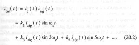
Note that neither the carrier frequency, carrier frequency harmonics, nor the original baseband signal is present at the output, i.e. the modulator is 'balanced'.
20.4.1 Ring bridge modulator/demodulator design considerations
20.4.1.1 Carrier compression.
With this type of modulator the ratio of the change in carrier power to the change in signal loss of the modulator, known as 'carrier compression', is approximately 10:1 so that accurate level stability of the carrier is not required.