

Class diagram
In software engineering, a class diagram in the Unified Modeling Language (UML) is a type of static structure diagram that describes the structure of a system by showing the system's classes, their attributes, operations (or methods), and the relationships among the classes.
Contents [hide]
|
[Edit] Overview
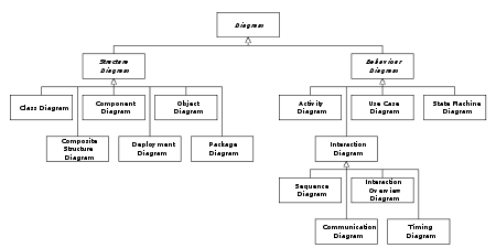
Hierarchy of UML 2.0 Diagrams, shown as a class diagram. The individual classes are represented just with one compartment, but they often contain up to three compartments.
The class diagram is the main building block of object oriented modelling. It is used both for general conceptual modelling of the systematics of the application, and for detailed modelling translating the models into programming code. Class diagrams can also be used for data modeling.[1] The classes in a class diagram represent both the main objects and or interactions in the application and the objects to be programmed. In the class diagram these classes are represented with boxes which contain three parts: [2]

A class with three sections.
The upper part holds the name of the class
The middle part contains the attributes of the class
The bottom part gives the methods or operations the class can take or undertake
In the design of a system, a number of classes are identified and grouped together in a class diagram which helps to determine the static relations between those objects. With detailed modeling, the classes of the conceptual design are often split into a number of subclasses.
In order to further describe the behavior of systems, these class diagrams can be complemented by state diagram or UML state machine. Also instead of class diagrams Object role modeling can be used if you just want to model the classes and their relationships.[2]
[Edit] Members
UML provides mechanisms to represent class members, such as attributes and methods, and additional information about them.
[Edit] Visibility
To specify the visibility of a class member (i.e., any attribute or method) these are the following notations that must be placed before the member's name [3]: All the Visibility of a Class Members Are:
+ Public
- Private
# Protected
~ Package
/ Derived
underline Static