

- •500 Engine Data
- •500.00 Main Data for GenSets
- •500.01(01H) Introduction
- •500.02(01H) Safety
- •500.05(01H) Cross Section
- •500.10(01H) Key for Engine Designation
- •500.11(01H) Designation of Cylinders
- •500.12(01H) Engine Rotation Clockwise
- •500.20(01H) Code identification for Instruments
- •500.35(01H) Data for Pressure and Tolerance
- •500.35(11H) Data for Pressure and Tolerance
- •500.40(01S) Data for Torque Moment
- •500.45(01H) Declaration of Weight
- •500.50(01H) Ordering of Spare Parts
- •500.55(01H) Service Letters
- •500.60(01H) Conversion Table
- •500.65(01H) Basic Symbols for Piping
- •501 Operation of Engine
- •501.01(01H) Operating
- •501.05(01H) Out-of Service
- •501.10(01H) Starting-up after Out of Service Periods
- •501.15(02H) Guidelines for Longterm Low-Load Operation on HFO
- •501.25(01H) Operating a Diesel Engine at Low Frequency
- •502 Engine Performance and Condition
- •502.01(01H) Engine Performance and Condition
- •502.05(01H) Condensate Amount
- •502-01.00(01H) Engine Performance Data
- •503 Trouble Tracing
- •503.01(01H) Starting Failures
- •503.01(02H) Starting Failures
- •503.02(01H) Faults in Fuel Oil System
- •503.03(01H) Disturbances during Running
- •503.04(01H) Ignition in Crankcase
- •503.06(01H) Trouble Shooting Guide for Turbine Starter
- •503.09(01H) Trouble Shooting for Cooling Water System
- •503.10(01H) Trouble Shooting for Lubricating Oil Cooler
- •504.01(01H) Lubricating Oil Specification
- •504.01(05H) Lubricating Oil Specification
- •504.03(01H) Maintenance of Lubricating Oil Condition
- •504.05(01H) Lubricating Points
- •504.06(01H) Lubricating Oil in Base Frame
- •504.06(04H) Lubricating Oil in Base Frame
- •504.20(02H) Fuel Oil Specification
- •504.20(04H) Fuel Oil Specification
- •504.25(01H) Fuel Oil Quality
- •504.26(01H) Nomogram for Determination of CCAI
- •504.26(02H) Nomogram for Determination of CCAI
- •504.27(01H) Analysis Data
- •504.30(01H) Fuel Oil Cleaning
- •504.40(01H) Fresh Water System Treatment
- •504.40(02H) Freshwater System Treatment
- •505 Cylinder Head
- •505.01(01H) Cylinder Head
- •505-01.00(01H) Dismantling of Cylinder Head
- •505-01.05(01H) Inspection of Inlet Valve, Exhaust Valve and Valve Guide
- •505-01.15(01H) Valve Rotator
- •505-01.20(01H) Replacement of Valve Guide
- •505-01.26(01H) Indicator Valve
- •505-01.30(01H) Replacement of Sleeve for Fuel Injector
- •505-01.35(01H) Replacement of Valve Seat Ring
- •505-01.40(01H) Mounting of Cylinder Head
- •505-01.45(01H) Inspection of Cylinder Head Cooling Water Space
- •50501-01H Cylinder Head
- •50502-01H Valve Spindles and Valve Gear
- •50508-01H Indicator Valve
- •50510-01H Cylinder Head, Top Cover
- •506 Piston, Connecting Rod and Cylinder Liner
- •506.01(01H) Piston, Connecting Rod and Cylinder liner
- •506-01.05(01H) Separation of Piston and Connecting Rod
- •506-01.10(01H) Piston
- •506-01.15(01H) Connecting Rod
- •506-01.25(01H) Tightening and Check of Connecting Rod Screws
- •506-01.30(01H) In-situ Inspection of Connecting Rod Big-end Bearing
- •506-01.35(01H) Inspection and Honing of Cylinder Liner
- •506-01.40(01H) Replacement of Cylinder Liner
- •50601-01H Piston and Connecting Rod
- •507 Camshaft and Camshaft Drive
- •507.01(01H) Camshaft and Camshaft Drive
- •507-01.00(01H) Check of Camshaft and Camshaft Drive
- •507-01.05(01H) Inspection and Replacement of Camshaft Bearing
- •507-01.20(01H) Adjustment of Camshaft
- •50701-01H Intermediate Wheel
- •50705-01H Camshaft and Camshaft Bearing
- •50705-07H Camshaft and Camshaft Bearing
- •508-01.00(01S) Inspection of Valve Roller Guides
- •50801-01H Roller Guide and Push Rods
- •509.01(01H) Control and Safety Systems
- •509.05(01H) Instruments and Automatics
- •509.10(02H) Lambda Controller
- •509.35(01H) Starting Box
- •509-01.05(01H) Functional Test and Adjustment of Overspeed Trip
- •509-05.00(01S) Adjustment and Test of ON/OFF Pressostate
- •509-05.01(01S) Adjustment and Test of ON/OFF Thermostate
- •50903-01H Overspeed Device
- •50905-03H Prelubricating Oil Alarm (LAL 25)
- •50905-04H Instrument Panel
- •50907-02H Thermometer
- •50908-01H Pick-up
- •50910-01H Lambda Controller
- •50935-01H Starting Box
- •510 Crankshaft and Main Bearings
- •510.01(01H) Crankshaft and Main Bearings
- •510-01.00(05H) Checking of Main Bearings Alignment (Autolog)
- •510-01.05(01H) Inspection of Main Bearing Shells
- •510-01.10(01H) Inspection of Guide Bearing Shells
- •51001-01H Crankshaft
- •51002-02H Resilient Gear Wheel
- •51003-02H Flywheel with Gear Rim
- •511S Engine Frame and Base Frame
- •511.01(01H) Engine Frame and Base Frame
- •511-01.00(01H) Functional Test of Crankcase Safety Relief Valves
- •51101-02H Frame with Main Bearings
- •51102-02H Mounting of Pumps
- •51106-02H Covers on Frame
- •51106-03S Covers on Frame
- •512 Turbocharger System
- •512.01(01H) Turbocharger System
- •512-01.00(01H) Overhaul of Charging Air Cooler
- •512-15.00(01H) Water Washing of Turbine Side
- •51202-01S Exhaust Pipe Arrangement
- •51203-03H Turbocharging Arrangement
- •513 Compressed Air System
- •513.01(01S) Compressed Air System
- •513.01.30(01H) Overhaul, Test and Inspection of Turbine Starter
- •513-01.40(01H) Main Starting Valve
- •513-01.90(01H) Check of Compressed Air Piping System
- •51309-01H Turbine Starter
- •51310-01H Main Starting Valve
- •51314-01S Starting Valve
- •51315-03H Main Stop Valve
- •51316-03H Air Strainer
- •51319-02H Safety Valve
- •51320-01H ON-OFF Valve for Jet System
- •51321-01H Air Filter
- •514 Fuel Oil System
- •514.01(01H) Internal Fuel Oil System
- •514-01.05(01H) Fuel Injection Pump and Fuel Injection Pipe
- •514-01.10(02H) Fuel Injection Valve
- •514-01.15(01H) Fuel Oil Split Filter
- •514-01.90(01H) Check of Fuel Oil Piping System
- •514-05.01(01H) Adjustment of The Maximum Combustion Pressure
- •51401-01H Fuel Injection Pump
- •51402-01H Fuel Injection Valve
- •51403-01H Fuel Oil Filter Duplex
- •51404-01H Fuel Injection Pipe
- •51430-01H Pipes on Cylinder Section
- •515 Lubricating Oil System
- •515.01(01H) Internal Lubricating Oil System
- •515.06(01H) Lubricating Oil Cooler
- •515-01.00(01H) Lubricating Oil Pump, Engine Driven
- •515-01.10(01H) Lubricating Oil Filter
- •515-01.20(01H) Lubricating Oil, Thermostatic Valve
- •515-01.90(01H) Check of Lubricating Oil Piping System
- •515-06.00(02H) Lubricating Oil Cooler
- •51501-03H Lubricating Oil Pump (Gear Driven)
- •51502-01H Lubricating Oil Filter (Type A)
- •51502-02H Lubricating Oil Filter (Suppl. for Plate 51502-01H)
- •51504-01H Prelubricating Pump
- •51506-01H Lubricating Oil Cooler
- •51525-01H Hand Wing Pump
- •51530-01H Lubricating Oil Separator
- •516 Cooling Water System
- •516.01(01H) Cooling Water System
- •516.04(01H) Cooling Water Thermostatic Valve
- •516-01.90(01H) Check of Cooling Water System
- •516.04-00(01H) Cooling Water, Thermostatic Valve
- •51604-01H Cooling Water Thermostatic Valve
- •51610-01H High Temperature Fresh Water Pump
- •51625-01H Pipes on Cylinder Head
- •51635-01H Preheater - Fresh Water
- •517 Special Equipment
- •518 Driven Machinery
- •519 Specific Plant Information
- •519.03(01S) Resilient Mounting of Generating Sets
- •519-03.00(01S) Fitting Instructions for Resilient Mounting of GenSets
- •519-03.00(02S) Fitting Instructions for Resilient Mounting of GenSets
- •519-03.00(03S) Fitting Instructions for Resilient Mounting of GenSets
- •519-03.05(01S) Replacement of Conicals
- •519-03.10(01S) Replacement of Conicals
- •520 Tools
- •520.01(01H) Introduction to Spare Part Plates for Tools
- •520-01.05(01H) Application of Hydraulic Tools
- •520-01.10(01H) Maintenance of Hydraulic Tools
- •520-01.15(01H) Tightening with Torque Spanner
Working Card
Page 1 (2)
Replacement of Conicals |
519-03.05 |
|
Edition 01S |
|
|
L23/30H
08028-0D/H5250/94.08.12
Safety precautions:
Stopped engine
Shut-off starting air
Shut-off cooling water
Shut-off fuel oil
Shut-off cooling oil
Stopped lub. oil circulation
Description:
Replacement of conicals.
Starting position:
Safety precautions.
Related procedure:
Fitting instructions for resilient mounting.
Man power: |
|
|
|
|
Working time |
: xxx |
hour |
|
|
Capacity |
: |
2 |
men |
|
Data: |
|
|
|
|
Data for pressure and tolerance |
(Page 500.35 |
|||
Data for torque moment |
(Page 500.40 |
|||
Declaration of weight |
|
(Page 500.45 |
||
Special tools:
Plate no Item no |
Note |
Hand tools:
Ring and open-end spanner, 22mm Ring and open-end spanner, 30mm Hydraulic jack
Spare and wearing parts:
Plate no Item no |
Qty/ |
96.03-EO0S-G
519-03.05 |
Replacement of Conicals |
Edition 01S |
|
|
|
Working Card
Page 2 (2)
L23/30H
Replacement of Conicals
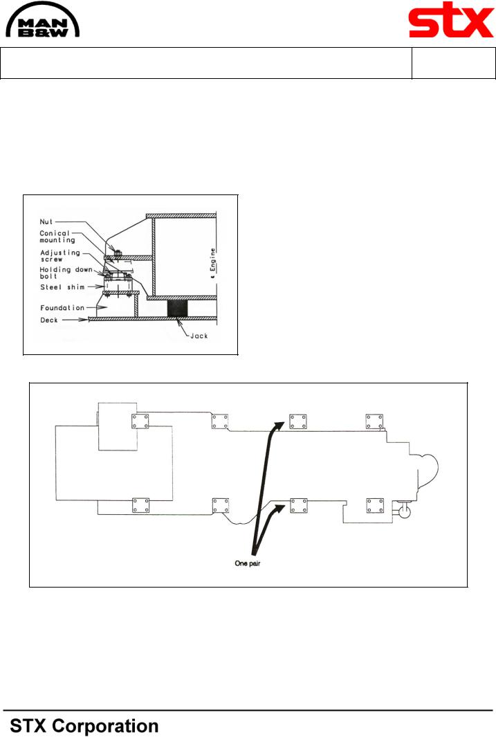
1.Loosen all conicals in one side.
2.Mount a jack under the base frame, see fig 1.
3.Lift the GenSet until the steel shim can be removed. This will give enough space for removing damaged conical.
4.Mount the GenSet conical.
Note! Conicals should only be replaced in pairs, see fig 2 and plate 51903.
5.Lower the GenSet again.
6.Repeat items 1-5 for the other side.
7.Adjust the conicals, see Working Card 51903.00 “Fitting Instructions for Resilient Mounting of GenSet.
Fig 1 Removal of conicals
Fig 2 The conicals must be pairs
08028-0D/H5250/94.08.12
96.03-EO0S-G

08028-0D/H5250/94.08.12
|
Page 1 (2) |
|
Replacement of Conicals |
|
519-03.10 |
|
Working Card |
|
|
|
|
|
|
|
|
|
|
|
Edition 01S |
|
|
|
|
|
|
L23/30H |
|
|
|
|
|
|
||
|
|
|
|
|
|
|
|
Safety precautions: |
Special tools: |
|
|
|
|
|
Stopped engine |
Plate no Item no |
Note |
|||
|
Shut-off starting air |
|
|
|
|
|
□Shut-off cooling water
□Shut-off fuel oil
□Shut-off cooling oil
□Stopped lub. oil circul.
Description:
Control and adjustment of conicals.
Hand tools:
Starting position:
Ring and open-end spanner.
Feeler gauge, 1-2 mm.
Related procedure:
Check of crankshaft deflection (autolog).
Man power: |
|
|
|
Spare and wearing parts: |
|
|
|
|
|
Plate no Item no |
Qty/ |
||
Working time |
: |
2 |
hour |
|||
|
|
|||||
Capacity |
: |
1 |
man |
|
|
|
Data: |
|
|
|
|
|
|
Data for pressure and tolerance |
(Page 500.35) |
|
||||
Data for torque moment |
(Page 500.40) |
|
||||
Declaration of weight |
(Page 500.45) |
|
||||
96.27-EO0S-G

519-03.10 |
Replacement of Conicals |
Edition 01S |
|
|
|
Working Card
Page 2 (2)
L23/30H
Visual Check
What to Check
1.Check for oil deposits on the rubber element.
2.Check for loose mounting bolts.
3.Check for damage in the rubber element. Result of visual Check
If |
Then |
everything is OK |
continue to next conical |
oil deposits on rubber |
clean rubber element |
element are observed |
|
loose mounting bolts |
fasten mounting bolts |
damage to conicals is |
replace conical accord- |
observed |
ing to Working Card |
|
519-03.05 |
Clearance Check |
|
|
|
What to Check |
|
4.Check clearance on all conicals between steel shim and internal buffer through the slot in the base casting of the conical (see fig 1) with a feeler gauge of approx. 2mm.
Result of Clearance Check |
|
|
|
||
If |
|
Then |
|
|
|
everything is OK |
check is completed |
||||
everything is |
not OK |
adjust |
conicals |
which |
|
|
|
do not comply with the |
|||
|
|
clearance |
demands |
||
|
|
acc. To item 2.3. Re- |
|||
|
|
check |
all |
concals acc. |
|
|
|
To item 2.1. |
|
||
everything is |
still not |
replace conical |
acc. to |
||
OK |
|
Working |
Card |
519- |
|
|
|
03.05 |
|
|
|
|
|
|
|
|
|
Adjustment of conicals
5.Remove protective cap by loosen the nut (1).
6.Turn internal buffer (2) clockwise until it makes contact with the steel Shim (4).
7.Turn internal buffer (2) anti-clockwise until it makes contact with the conical base casting
(3). This must be done in four full rotations.
8.Turn internal buffer (2) two full rotations clockwise. This will ensure full vertical movement for the buffer.
9.Check all conicals again.
10.Tighten the nut (1), see page 500.40 and at the same time block the internal buffer (2) with a spanner.
08028-0D/H5250/94.08.12
Fig 1 Conical
96.27-EO0S-G