


Index
Page 1 (1)
Engine Performance and Condition |
502 |
|
|
|
L23/30H |
Description |
|
Engine Performance and Condition ................................................................................. |
502.01 (01H) |
Evaluation of Readings Regarding Combustion Condition ............................................... |
502.02 (01H) |
Condensate Amount ........................................................................................................ |
502.05 (01H) |
Working Card
Engine Performance Data .......................................................................................... |
502-01.00 (01H) |
Plates
08028-0D/H5250/94.08.12
96.03 - ES0U

Description |
Engine Performance and Condition |
502.01 |
|
Page 1 (3) |
Edition 01H |
||
|
|||
|
|
||
|
|
|
08028-0D/H5250/94.08.12
Performance Data and Engine Condition
During operation small alterations of the engine condition continuously take place as a result of combustion,includingfoulingofairwaysandgasways, formation of deposits, wear, corrosion, etc. If continuously recorded, these alterations of the condition can give valuable information about the operational and maintenance condition of the engine. Continual observations can contribute to forming a precise and valuable basis for evaluation of the optimal operation and maintenance programmes for the individual plant.
We recommend taking weekly records of the most importantperformancedataoftheengineplant.During recording (working card 502-01.00 can be used), the observations are to be continually compared in order to ascertain alterations at an early stage and before these exert any appreciable influence on the operation of the plant.
As a reference condition for the performance data, the testbed measurements of the engine or possibly the measurementstakenduringtheseatrialatthedelivery of the ship can be used. If considerable deviations from the normal condition are observed, it will, in a majority of cases, be possible to diagnose the cause of such deviations by means of a total evaluation and a set of measurements, after which possible adjustment/overhauls can be decided and planned.
Evaluation of Performance Data
For example, fouling of the air side of the air cooler will manifest itself in an increasing pressure drop, lower charge air pressure and an increased exhaust temperature level (with consequential influence on the overhaul intervals for the exhaust valves).
Fouling of the turbine side of the turbocharger will, in itsfirstphase,manifestitselfinincreasingturbocharger revolutions on account of increased gas velocity through the narrowed nozzle ring area. In the long run, the charging air quantity will decrease on account of the greater flow resistance through the nozzle ring, resultinginhigherwall temperaturesinthe combustion chambers.
L23/30H
An increase of charge air temperature involves a correspondingincreaseoftheexhaustgastemperature level in a ratio of about 1:1.5, i.e. 1°C higher charge air temperature causes about 1.5°C higher exhaust gas temperature.
Reduction of the charge air pressure results in a corresponding reduction of the compression pressure and max. combustion pressure. When checking the max. pressure adjustment of the engine, it is therefore to be ensured that the existing charge air pressure is correct.
The injected amount of fuel is equivalent to supplied energy and is thus an expression of the load and mean pressure of the engine. The fuel pump index can therefore be assumed to be proportional to the mean pressure. Consequently, it can be assumed that the connected values of the pump index are proportional to the load.
The specific fuel consumption, SFOC (measured by weight) will, on the whole, remain unaltered whether the engine is operating on HFO or on MDO, when considering the difference in calorimetric combustion value. However, when operation on HFO, the combination of density and calorific value may result in an alteration of up to 6% in the volumetric consumption at a given load. This will result in a corresponding alteration in the fuel pump index, and regard should be paid to this when adjusting the overload preventative device of the engine.
Abrasive particles in the fuel oil result in wear of fuel pumps and fuel valve nozzles. Effective treatment of the fuel oil in the purifier can limit the content of abrasive particles to a minimum. Worn fuel pumps will result in an increase of the index on account of an increased loss in the pumps due to leakage.
When evaluating operational results, a distinction is to be made between alterations which affect the whole engine (all cylinder units) and alterations which occur in only one or a few cylinders. Deviations occuring for afewcylindersare,asarule,causedbymalfunctioning of individual components, for example, a fuel valve with a too low opening pressure, blocked nozzle holes, wear, or other defects, an inlet or exhaust valve with wrongly adjusted clearance, burned valve seat etc.
96.20 - ES0U-G

502.01 |
Engine Performance and Condition |
Description |
Edition 01H |
|
Page 2 (3) |
|
|
|
|
|
|
L23/30H |
|
|
The operational observations supplemented by the daily routine monitoring contribute to ensuring that faulty adjustments and other deviations in the performance of individual components are observed in time to avoid operational disturbances and so that normal routine overhauls can be carried out as scheduled.
If abnormal or incomprehensible deviations in the operation are recorded, expert assistance for the evaluation of these should be obtained.
Turbochargers
Service experience has shown that the turbine side is exposed to increased fouling when operating on HFO.
The rate of fouling and thereby the influence on the operation of the engine is greatest for small turbochargers where the flow openings between the guide vanes of the nozzle ring are relatively small. Deposits especially occur on the guide vanes of the nozzle ring and on the rotor blades. In the long run, fouling will reduce the efficiency of the turbocharger and thereby also the quantity of air supplied for the combustion of the engine. A reduced quantity of air willresultinhigherwalltemperaturesinthecombustion spaces of the engine.
Detailed information and instructions regarding water washing of the turbocharger are given in the section 512.
Fuel Valves
Assuming that the fuel oil is effectively purified and that the engine is well maintained, the operational conditionsfor thefuelvalvesand theoverhaulintervals will not normally be essentially altered when operating on HFO.
If, for any reason, the surface temperature of the fuel valve nozzle is lower than the condensation temperature of sulphuric acid, sulphuric acid condensate can form and corrosion take place (cold corrosion). The formation of sulphuric acid further depends on the sulphur content in the fuel oil.
Normally, the fuel nozzle temperature will be higher than the approx. 180°C, at which cold corrosion starts to occur.
Abrasive particles in the fuel oil involve a heavier wear of the fuel valve needle, seat, and fuel nozzle holes. Therefore, abrasive particles are, to the greatest possible extent, to be removed at the purification.
Exhaust Valves
The overhaul intervals of exhaust valves is one of the key parameters when reliability of the entire engine is to be judged. Operation on HFO has a negative effect on these intervals. The performance of the exhaust valves is therefore extremely informative.
Especially under favourable conditions, fuel qualities with a high vanadium and sodium content will promote burning of the valve seats. Combinations of vanadium and sodium oxides with a corrosive effect will be formed during the combustion. This adhesive ash may, especially in the case of increased valve temperatures, form deposits on the seats. An increasing sodium content will reduce the melting point and thereby the adhesive temperature for the ash, which will involve a greater risk for deposits. This condition will be especially unfavourable when the weight ratio Na increases beyond 1:3.
Va
The exhaust valve temperature depends on the actual maintenance condition and the load of the engine. With correct maintenance, the valve temperature is kept at a satisfactory low level at all loads. The air supply to the engine (turbocharger/air cooler) and the maximum pressure adjustment are key parameters in this connection.
It is important for the functioning of the valves that the valve seats are overhauled correctly in accordance with our instructions.
The use of rotocaps ensures a uniform distribution of temperature on the valves.
08028-0D/H5250/94.08.12
96.20 - ES0U-G

Description |
Engine Performance and Condition |
502.01 |
|
Page 3 (3) |
Edition 01H |
||
|
|||
|
|
||
|
|
|
Air Inlet Valves
The operational conditions of the air inlet valves are not substantially altered when using residual fuel.
Fuel Pumps
Assuming effective purification of the fuel oil, the operation of the fuel pumps will not be very much affected.
The occurrence of increasing abrasive wear of plunger and barrel can be a consequence of insufficient purification of the fuel oil, especially if using a fuel which contains residues from catalytic cracking. Water in the fuel oil involves an increased risk of cavitation in connection with pressure impulses occurring at the cutting-off of the fuel pump. A fuel withahighasphaltcontenthasdeterioratinglubricating properties and can, in extreme cases, result in sticking of the fuel pump plungers.
L23/30H
Engine Room Ventilation, Exhaust System
Good ventilation of the engine room and a suitable location of the fresh air intake on the deck are important. Seawater in the intake air might involve corrosive attack and influence the overhaul intervals for the exhaust valves.
The fresh air supply (ventilation) to the engine room is to correspond to approximately 1.5 times the air consumption of the engines and possible boilers in operation.Sub-pressureintheengineroomwillinvolve an increased exhaust temperature level.
The exhaust back-pressure measured after the turbochargers at full load should not exceed 250-300 mm water gauge. An increase of the exhaust backpressure will also involve an increased exhaust valve temperature level.
08028-0D/H5250/94.08.12
96.20 - ES0U-G
Description |
Evaluation of Readings Regarding |
502.02 |
Page 1 (1) |
Combustion Condition |
Edition 01H |
|
08028-0D/H5250/94.08.12
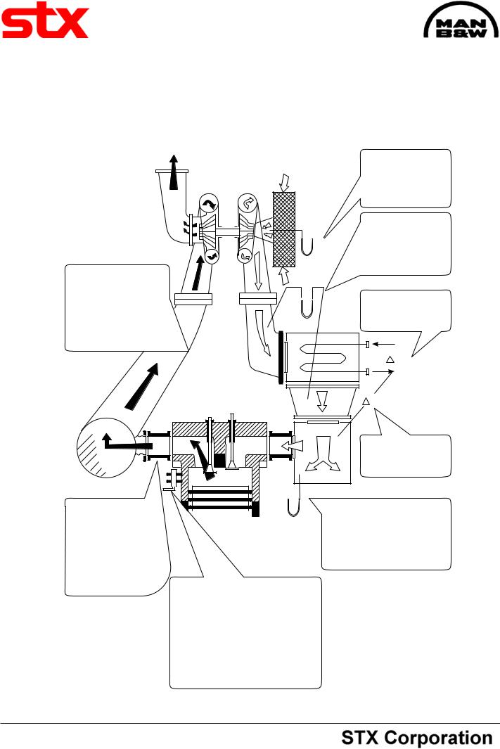
ALL CYLINDERS
Exhaust temp. increasing:
Air system fouled
(Air filter-blower-cooler). Exhaust system fouled (nozzle ring, turbine wheel).
ONE CYLINDER Exhaust temp. increasing: Fuel valve needs overhaul. Compression too low owing to leakage of exhaust valve or piston ring blow-by.
Pcomp and Pmax are measured by means of max. pressure gauge.
Pcomp too low: Leaky combustion chamber, charging air pressure too low.
Pmax too low:
P comp too low, ignition too late.
L23/30H
PRESSURE DROP INCREASING (limit 50%)
Air filters fouled.
PRESSURE DROP INCREASING (limit 50%)
Air side of cooler fouled.
TEMP. DIFFERENCE
TOO LARGE
Water flow too small
T
T
TEMP. DIFFERENCE
TOO LARGE
Air cooler fouled.
DECREASING CHARGE AIR
PRESSURE:
Decreasing air amount. Fouled turbocharger, air filter or charge
air cooler (air side).
See also:
Engine Performance and condition 501.01
92.03 - ES0S-G