

- •500 Engine Data
- •500.00 Main Data for GenSets
- •500.01(01H) Introduction
- •500.02(01H) Safety
- •500.05(01H) Cross Section
- •500.10(01H) Key for Engine Designation
- •500.11(01H) Designation of Cylinders
- •500.12(01H) Engine Rotation Clockwise
- •500.20(01H) Code identification for Instruments
- •500.35(01H) Data for Pressure and Tolerance
- •500.35(11H) Data for Pressure and Tolerance
- •500.40(01S) Data for Torque Moment
- •500.45(01H) Declaration of Weight
- •500.50(01H) Ordering of Spare Parts
- •500.55(01H) Service Letters
- •500.60(01H) Conversion Table
- •500.65(01H) Basic Symbols for Piping
- •501 Operation of Engine
- •501.01(01H) Operating
- •501.05(01H) Out-of Service
- •501.10(01H) Starting-up after Out of Service Periods
- •501.15(02H) Guidelines for Longterm Low-Load Operation on HFO
- •501.25(01H) Operating a Diesel Engine at Low Frequency
- •502 Engine Performance and Condition
- •502.01(01H) Engine Performance and Condition
- •502.05(01H) Condensate Amount
- •502-01.00(01H) Engine Performance Data
- •503 Trouble Tracing
- •503.01(01H) Starting Failures
- •503.01(02H) Starting Failures
- •503.02(01H) Faults in Fuel Oil System
- •503.03(01H) Disturbances during Running
- •503.04(01H) Ignition in Crankcase
- •503.06(01H) Trouble Shooting Guide for Turbine Starter
- •503.09(01H) Trouble Shooting for Cooling Water System
- •503.10(01H) Trouble Shooting for Lubricating Oil Cooler
- •504.01(01H) Lubricating Oil Specification
- •504.01(05H) Lubricating Oil Specification
- •504.03(01H) Maintenance of Lubricating Oil Condition
- •504.05(01H) Lubricating Points
- •504.06(01H) Lubricating Oil in Base Frame
- •504.06(04H) Lubricating Oil in Base Frame
- •504.20(02H) Fuel Oil Specification
- •504.20(04H) Fuel Oil Specification
- •504.25(01H) Fuel Oil Quality
- •504.26(01H) Nomogram for Determination of CCAI
- •504.26(02H) Nomogram for Determination of CCAI
- •504.27(01H) Analysis Data
- •504.30(01H) Fuel Oil Cleaning
- •504.40(01H) Fresh Water System Treatment
- •504.40(02H) Freshwater System Treatment
- •505 Cylinder Head
- •505.01(01H) Cylinder Head
- •505-01.00(01H) Dismantling of Cylinder Head
- •505-01.05(01H) Inspection of Inlet Valve, Exhaust Valve and Valve Guide
- •505-01.15(01H) Valve Rotator
- •505-01.20(01H) Replacement of Valve Guide
- •505-01.26(01H) Indicator Valve
- •505-01.30(01H) Replacement of Sleeve for Fuel Injector
- •505-01.35(01H) Replacement of Valve Seat Ring
- •505-01.40(01H) Mounting of Cylinder Head
- •505-01.45(01H) Inspection of Cylinder Head Cooling Water Space
- •50501-01H Cylinder Head
- •50502-01H Valve Spindles and Valve Gear
- •50508-01H Indicator Valve
- •50510-01H Cylinder Head, Top Cover
- •506 Piston, Connecting Rod and Cylinder Liner
- •506.01(01H) Piston, Connecting Rod and Cylinder liner
- •506-01.05(01H) Separation of Piston and Connecting Rod
- •506-01.10(01H) Piston
- •506-01.15(01H) Connecting Rod
- •506-01.25(01H) Tightening and Check of Connecting Rod Screws
- •506-01.30(01H) In-situ Inspection of Connecting Rod Big-end Bearing
- •506-01.35(01H) Inspection and Honing of Cylinder Liner
- •506-01.40(01H) Replacement of Cylinder Liner
- •50601-01H Piston and Connecting Rod
- •507 Camshaft and Camshaft Drive
- •507.01(01H) Camshaft and Camshaft Drive
- •507-01.00(01H) Check of Camshaft and Camshaft Drive
- •507-01.05(01H) Inspection and Replacement of Camshaft Bearing
- •507-01.20(01H) Adjustment of Camshaft
- •50701-01H Intermediate Wheel
- •50705-01H Camshaft and Camshaft Bearing
- •50705-07H Camshaft and Camshaft Bearing
- •508-01.00(01S) Inspection of Valve Roller Guides
- •50801-01H Roller Guide and Push Rods
- •509.01(01H) Control and Safety Systems
- •509.05(01H) Instruments and Automatics
- •509.10(02H) Lambda Controller
- •509.35(01H) Starting Box
- •509-01.05(01H) Functional Test and Adjustment of Overspeed Trip
- •509-05.00(01S) Adjustment and Test of ON/OFF Pressostate
- •509-05.01(01S) Adjustment and Test of ON/OFF Thermostate
- •50903-01H Overspeed Device
- •50905-03H Prelubricating Oil Alarm (LAL 25)
- •50905-04H Instrument Panel
- •50907-02H Thermometer
- •50908-01H Pick-up
- •50910-01H Lambda Controller
- •50935-01H Starting Box
- •510 Crankshaft and Main Bearings
- •510.01(01H) Crankshaft and Main Bearings
- •510-01.00(05H) Checking of Main Bearings Alignment (Autolog)
- •510-01.05(01H) Inspection of Main Bearing Shells
- •510-01.10(01H) Inspection of Guide Bearing Shells
- •51001-01H Crankshaft
- •51002-02H Resilient Gear Wheel
- •51003-02H Flywheel with Gear Rim
- •511S Engine Frame and Base Frame
- •511.01(01H) Engine Frame and Base Frame
- •511-01.00(01H) Functional Test of Crankcase Safety Relief Valves
- •51101-02H Frame with Main Bearings
- •51102-02H Mounting of Pumps
- •51106-02H Covers on Frame
- •51106-03S Covers on Frame
- •512 Turbocharger System
- •512.01(01H) Turbocharger System
- •512-01.00(01H) Overhaul of Charging Air Cooler
- •512-15.00(01H) Water Washing of Turbine Side
- •51202-01S Exhaust Pipe Arrangement
- •51203-03H Turbocharging Arrangement
- •513 Compressed Air System
- •513.01(01S) Compressed Air System
- •513.01.30(01H) Overhaul, Test and Inspection of Turbine Starter
- •513-01.40(01H) Main Starting Valve
- •513-01.90(01H) Check of Compressed Air Piping System
- •51309-01H Turbine Starter
- •51310-01H Main Starting Valve
- •51314-01S Starting Valve
- •51315-03H Main Stop Valve
- •51316-03H Air Strainer
- •51319-02H Safety Valve
- •51320-01H ON-OFF Valve for Jet System
- •51321-01H Air Filter
- •514 Fuel Oil System
- •514.01(01H) Internal Fuel Oil System
- •514-01.05(01H) Fuel Injection Pump and Fuel Injection Pipe
- •514-01.10(02H) Fuel Injection Valve
- •514-01.15(01H) Fuel Oil Split Filter
- •514-01.90(01H) Check of Fuel Oil Piping System
- •514-05.01(01H) Adjustment of The Maximum Combustion Pressure
- •51401-01H Fuel Injection Pump
- •51402-01H Fuel Injection Valve
- •51403-01H Fuel Oil Filter Duplex
- •51404-01H Fuel Injection Pipe
- •51430-01H Pipes on Cylinder Section
- •515 Lubricating Oil System
- •515.01(01H) Internal Lubricating Oil System
- •515.06(01H) Lubricating Oil Cooler
- •515-01.00(01H) Lubricating Oil Pump, Engine Driven
- •515-01.10(01H) Lubricating Oil Filter
- •515-01.20(01H) Lubricating Oil, Thermostatic Valve
- •515-01.90(01H) Check of Lubricating Oil Piping System
- •515-06.00(02H) Lubricating Oil Cooler
- •51501-03H Lubricating Oil Pump (Gear Driven)
- •51502-01H Lubricating Oil Filter (Type A)
- •51502-02H Lubricating Oil Filter (Suppl. for Plate 51502-01H)
- •51504-01H Prelubricating Pump
- •51506-01H Lubricating Oil Cooler
- •51525-01H Hand Wing Pump
- •51530-01H Lubricating Oil Separator
- •516 Cooling Water System
- •516.01(01H) Cooling Water System
- •516.04(01H) Cooling Water Thermostatic Valve
- •516-01.90(01H) Check of Cooling Water System
- •516.04-00(01H) Cooling Water, Thermostatic Valve
- •51604-01H Cooling Water Thermostatic Valve
- •51610-01H High Temperature Fresh Water Pump
- •51625-01H Pipes on Cylinder Head
- •51635-01H Preheater - Fresh Water
- •517 Special Equipment
- •518 Driven Machinery
- •519 Specific Plant Information
- •519.03(01S) Resilient Mounting of Generating Sets
- •519-03.00(01S) Fitting Instructions for Resilient Mounting of GenSets
- •519-03.00(02S) Fitting Instructions for Resilient Mounting of GenSets
- •519-03.00(03S) Fitting Instructions for Resilient Mounting of GenSets
- •519-03.05(01S) Replacement of Conicals
- •519-03.10(01S) Replacement of Conicals
- •520 Tools
- •520.01(01H) Introduction to Spare Part Plates for Tools
- •520-01.05(01H) Application of Hydraulic Tools
- •520-01.10(01H) Maintenance of Hydraulic Tools
- •520-01.15(01H) Tightening with Torque Spanner

Working Card |
Adjustment of The Maximum Combustion Pressure |
514-05.01 |
Page 1 (3) |
Edition 01H |
|
|
|
|
|
|
|
|
|
L23/30H |
08028-0D/H5250/94.08.12
Safety precautions:
Stopped engine

 Shut-off starting air
Shut-off cooling water
Shut-off fuel oil
Shut-off cooling oil
Stopped lub. oil circul.
Description:
Adjustment of the maximum combustion pressure for the cylinders one by one and for all cylinders in total.
Starting position:
Camshaft mounted and adjusted in
relation to the crankshaft (lead), 507-01.20 Intermediate wheel mounted.
Related procedure:
Manpower: |
|
|
|
Working time |
: |
2-5 |
hours |
Capacity |
: |
1 |
man |
Data: |
|
|
|
Data for pressure and tolerance |
(Page 500.35) |
Data for torque moment |
(Page 500.40) |
Declaration of weight |
(Page 500.45) |
Special tools: |
|
|
Plate no |
Item no |
Note |
52006 |
261 |
20 - 120 Nm. |
52010 |
011 |
|
52008 |
058 |
|
Hand tools:
Ring and open end spanner, 19 mm. Socket spanner, 19 mm.
Depth gauge. Plastic hammer.
Replacement and wearing parts:
Plate no |
Item no |
Qty / |
50801 |
124 |
1 set/cyl |
91.45 - ES0S-G
514-05.01 |
Adjustment of The Maximum Combustion Pressure |
Working Card |
Edition 01H |
Page 2 (3) |
|
|
|
|
|
|
|
L23/30H
If fuel oil valve, piston, inlet and exhaust valves as well as turbocharger and charge air cooler are working correct and the compression pressure Pcomp is normal the maximum combustion pressure will indicate the injection timing for the fuel oil pump.
If Pmax is too low it indicates that the injection timing is delayed.
If Pmax is too high it indicates that the injection timing is advanced.
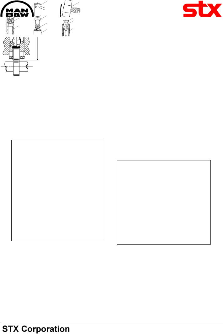
The injection timing can be altered by inserting or removing shims under the thrust piece on the roller guide, thus changing the measure “X”, see fig 1.
Measure "x"
Total height
Fig 1
Thinner and/or fewer shims (increase of the distance “X”) results in a delayed injection timing and a lower
Pmax.
Thicker and/or more shims (reduction of the distance “X”) results in an advanced injection timing and a higher Pmax.
If the distance “X” is to be changed the trigger (1) is used for dismantling of the thrust piece (2), whereafter the thickness and/or the number of shims (3) can be changed.
By changing “X” with 0.10 mm the maximum combustion pressure is changed with - see page 500.35.
After replacement of shims the thrust piece is remounted in the roller guide (4) with a soft hammer (5).
When changing “X” it must be ensured that the
|
|
|
5 |
1 |
Extractor |
2 |
Thrust piece |
3 |
Shims |
4 |
Roller guide |
5 |
Soft hammer |
|
|
Fig 3
|
|
|
|
|
|
|
|
0D/H5250/94.08.12-08028 |
Action |
|
|
|
Results |
|
|
|
|
|
|
|
|
|
|
|
||
|
|
|
|
|
|
|
|
|
Total height |
|
Distance |
|
Injection |
|
Max. combustion |
|
|
on roller guide |
|
"x" |
|
timing |
|
pressure |
|
|
|
|
|
|
|
|
|
|
|
increased |
- |
Reduced |
¯ |
Advanced |
- |
increased |
- |
|
|
|
|
|
|
|
|
|
|
Reduced |
¯ |
increased |
- |
Delayed |
¯ |
Reduced |
¯ |
|
|
|
|
|
|
|
|
|
|
Fig 2
91.45 - ES0S-G

Working Card |
Adjustment of The Maximum Combustion Pressure |
514-05.01 |
Page 3 (3) |
Edition 01H |
|
|
|
|
|
|
|
|
|
L23/30H |
distance between the upper edge of the roller guide housing and the thrust piece on the roller guide is not exceeded, when the roller is resting on the circular part of the fuel cam, see page 500.35.
In all cases “X” must be checked and adjusted, if necessary, when fuel oil pump, roller guide, roller guide housing and/or camshaft section have been replaced/dismantled.
Note: If several fuel oil pumps, roller guides, roller guide housings and/or camshaft sections are dismantled at the same time it is advisable to number the parts in order to facilitate remounting and adjustment.
If the maximum combustion pressure differs from the test bed records after adjustment of each individual pump the camshafts placement can be changed, as thecamshaftsgearwheelsareprovidedwithoblonged holes so that they can be turned in relation to the hub.
The gear wheel is provided with an engraved scale, see fig 4, and the hub of the cam shaft is provided with a mark.
When the screws, which fasten the gear wheel, are loosened the gear wheel is turned (by turning the crankshaft) in relation to the camshaft. By reading the angle in which the gear wheel is displaced in relation to the camshaft the altered Pmax can be calculated. A line on the scale corresponds to: see page 500.35.
If the crankshaft is turned in the engines normal direction of rotation the maximum combustion pressure P-max. is reduced.
Fig. 4
If the crankshaft is turned against the engines normal direction of rotation the maximum combustion pressure P-max. is increased.
After the adjustment the screws are fastened with a torque wrench, see page 500.40, and secured.
08028-0D/H5250/94.08.12
91.45 - ES0S-G
Plate
Page 1 (2)
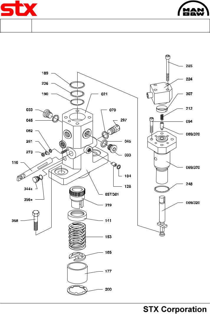
Fuel Injection Pump |
51401-01H |
|
|
L23/30H
08028-0D/H5250/94.08.12
94.23 - ES0S

51401-01H |
|
|
Fuel Injection Pump |
|
Plate |
|||||||
|
|
|
Page 2 (2) |
|||||||||
L23/30H |
|
|
|
|
|
|
|
|
|
|
||
|
|
|
|
|
|
|
|
|
|
|||
|
Item |
|
|
|
|
|
Item |
|
|
|
|
|
|
|
|
|
|
|
|
|
|
|
|
||
|
No. |
Qty. |
|
Designation |
Benævnelse |
|
No. |
Qty. |
Designation |
Benævnelse |
||
|
|
|
|
|
|
|
|
|
|
|
|
|
021 |
1/P |
|
Pump housing |
Pumpehus |
307 |
1/P |
Securing ring |
Beskyttelsesring |
||||
033 |
2/P |
|
Screw |
Skrue |
319 |
1/P |
Gear rim |
Tandkrans |
||||
045 |
2/P |
|
Packing ring |
Pakningsring |
320 |
1/P |
Plunger and barrel |
Stempel og cylinder |
||||
057 |
1/C |
|
Fuel injection pump, |
|
|
|
|
incl. non-return valve |
inkl. kontraventil |
|||
|
Fuel indsprøjtnings- |
|
|
|
for L23/30H, 900 rpm |
for L23/30H, 900 rpm |
||||||
|
|
|
|
complete for L23/30H, |
pumpe, komplet for |
|
|
|
|
|
|
|
|
|
|
|
720/750 rpm |
L23/30H, 720/750 rpm |
344+ |
1/P |
Screw |
Skrue |
|||
069 |
1/P |
|
Plunger and barrel |
Stempel og cylinder |
356+ |
1/P |
Packing ring |
Pakningsring |
||||
|
|
|
|
incl. non-return valve |
inkl. kontraventil for |
|
|
|
|
|
|
|
|
|
|
|
for L23/30H, |
L23/30H, 720/750 rpm |
368 |
2/P |
Screw |
Skrue |
|||
|
|
|
|
720/750 rpm |
|
|
|
|
|
|
|
|
070 |
1/P |
|
Joint washer |
|
381 |
1/C |
Fuel injection pump, |
Fuel indsprøjtnings- |
||||
|
Pakning |
|
|
|
complete for |
pumpe, komplet for |
||||||
082 |
2/P |
|
Washer |
Skive |
|
|
|
L23/30H, 900 rpm |
L23/30H, 900 rpm |
|||
|
|
|
|
|
|
|
|
|||||
094 |
4/P |
|
Screw |
Skrue |
|
|
|
+ Are not included in |
+ Indgår ikke i fuel ind- |
|||
104 |
1/P |
|
Circlip |
|
|
|
|
|||||
|
Låsering |
|
|
|
fuel injection pump, |
sprøjtningspumpe, |
||||||
116 |
1/P |
|
Regulating rod |
Reguleringsstang |
|
|
|
complete |
komplet |
|||
|
|
|
|
|
|
|
|
|||||
128 |
1/P |
|
Guide pin |
Styretap |
|
|
|
|
|
|
|
|
141 |
1/P |
|
Upper spring plate |
Øverste fjederplade |
|
|
|
|
|
|
|
|
153 |
1/P |
|
Spring |
Fjeder |
|
|
|
|
|
|
|
|
165 |
1/P |
|
Lower spring plate |
Nederste fjederplade |
|
|
|
|
|
|
|
|
177 |
1/P |
|
Thrust cap |
Trykhætte |
|
|
|
|
|
|
|
|
189 |
1/P |
|
O-ring |
O-ring |
|
|
|
|
|
|
|
|
190 |
1/P |
|
O-ring |
O-ring |
|
|
|
|
|
|
|
|
200 |
1/P |
|
Circlip |
Låsering |
|
|
|
|
|
|
|
|
212 |
1/P |
|
Spring |
Fjeder |
|
|
|
|
|
|
|
|
224 |
1/P |
|
Connecting piece |
Forbindelsesstykke |
|
|
|
|
|
|
|
|
236 |
1/P |
|
O-ring |
O-ring |
|
|
|
|
|
|
|
|
248 |
1/P |
|
O-ring |
O-ring |
|
|
|
|
|
|
|
|
261 |
1/P |
|
Pointer |
Viser |
|
|
|
|
|
|
|
|
273 |
1/P |
|
Nut |
Møtrik |
|
|
|
|
|
|
|
|
285 |
4/P |
|
Screw |
Skrue |
|
|
|
|
|
|
|
|
297 |
1/P |
|
Cap screw |
Hætteskrue |
|
|
|
|
|
|
|
|
|
|
|
|
|
|
|
|
|
|
|
|
|
When ordering spare parts, see also page 500.50. |
Ved bestilling af reservedele, se også side 500.50. |
||||
* |
= Only available as part of a spare parts kit. |
* |
= |
Kun tilgængelig som en del af et reservedelssæt. |
|
Qty./P |
= |
Qty./Pump |
Antal/P = |
Antal/Pumpe |
|
Qty./C |
= |
Qty./Cylinder |
Antal/C = |
Antal/Cylinder |
|
08028-0D/H5250/94.08.12
94.23 - ES0S