

- •500 Engine Data
- •500.00 Main Data for GenSets
- •500.01(01H) Introduction
- •500.02(01H) Safety
- •500.05(01H) Cross Section
- •500.10(01H) Key for Engine Designation
- •500.11(01H) Designation of Cylinders
- •500.12(01H) Engine Rotation Clockwise
- •500.20(01H) Code identification for Instruments
- •500.35(01H) Data for Pressure and Tolerance
- •500.35(11H) Data for Pressure and Tolerance
- •500.40(01S) Data for Torque Moment
- •500.45(01H) Declaration of Weight
- •500.50(01H) Ordering of Spare Parts
- •500.55(01H) Service Letters
- •500.60(01H) Conversion Table
- •500.65(01H) Basic Symbols for Piping
- •501 Operation of Engine
- •501.01(01H) Operating
- •501.05(01H) Out-of Service
- •501.10(01H) Starting-up after Out of Service Periods
- •501.15(02H) Guidelines for Longterm Low-Load Operation on HFO
- •501.25(01H) Operating a Diesel Engine at Low Frequency
- •502 Engine Performance and Condition
- •502.01(01H) Engine Performance and Condition
- •502.05(01H) Condensate Amount
- •502-01.00(01H) Engine Performance Data
- •503 Trouble Tracing
- •503.01(01H) Starting Failures
- •503.01(02H) Starting Failures
- •503.02(01H) Faults in Fuel Oil System
- •503.03(01H) Disturbances during Running
- •503.04(01H) Ignition in Crankcase
- •503.06(01H) Trouble Shooting Guide for Turbine Starter
- •503.09(01H) Trouble Shooting for Cooling Water System
- •503.10(01H) Trouble Shooting for Lubricating Oil Cooler
- •504.01(01H) Lubricating Oil Specification
- •504.01(05H) Lubricating Oil Specification
- •504.03(01H) Maintenance of Lubricating Oil Condition
- •504.05(01H) Lubricating Points
- •504.06(01H) Lubricating Oil in Base Frame
- •504.06(04H) Lubricating Oil in Base Frame
- •504.20(02H) Fuel Oil Specification
- •504.20(04H) Fuel Oil Specification
- •504.25(01H) Fuel Oil Quality
- •504.26(01H) Nomogram for Determination of CCAI
- •504.26(02H) Nomogram for Determination of CCAI
- •504.27(01H) Analysis Data
- •504.30(01H) Fuel Oil Cleaning
- •504.40(01H) Fresh Water System Treatment
- •504.40(02H) Freshwater System Treatment
- •505 Cylinder Head
- •505.01(01H) Cylinder Head
- •505-01.00(01H) Dismantling of Cylinder Head
- •505-01.05(01H) Inspection of Inlet Valve, Exhaust Valve and Valve Guide
- •505-01.15(01H) Valve Rotator
- •505-01.20(01H) Replacement of Valve Guide
- •505-01.26(01H) Indicator Valve
- •505-01.30(01H) Replacement of Sleeve for Fuel Injector
- •505-01.35(01H) Replacement of Valve Seat Ring
- •505-01.40(01H) Mounting of Cylinder Head
- •505-01.45(01H) Inspection of Cylinder Head Cooling Water Space
- •50501-01H Cylinder Head
- •50502-01H Valve Spindles and Valve Gear
- •50508-01H Indicator Valve
- •50510-01H Cylinder Head, Top Cover
- •506 Piston, Connecting Rod and Cylinder Liner
- •506.01(01H) Piston, Connecting Rod and Cylinder liner
- •506-01.05(01H) Separation of Piston and Connecting Rod
- •506-01.10(01H) Piston
- •506-01.15(01H) Connecting Rod
- •506-01.25(01H) Tightening and Check of Connecting Rod Screws
- •506-01.30(01H) In-situ Inspection of Connecting Rod Big-end Bearing
- •506-01.35(01H) Inspection and Honing of Cylinder Liner
- •506-01.40(01H) Replacement of Cylinder Liner
- •50601-01H Piston and Connecting Rod
- •507 Camshaft and Camshaft Drive
- •507.01(01H) Camshaft and Camshaft Drive
- •507-01.00(01H) Check of Camshaft and Camshaft Drive
- •507-01.05(01H) Inspection and Replacement of Camshaft Bearing
- •507-01.20(01H) Adjustment of Camshaft
- •50701-01H Intermediate Wheel
- •50705-01H Camshaft and Camshaft Bearing
- •50705-07H Camshaft and Camshaft Bearing
- •508-01.00(01S) Inspection of Valve Roller Guides
- •50801-01H Roller Guide and Push Rods
- •509.01(01H) Control and Safety Systems
- •509.05(01H) Instruments and Automatics
- •509.10(02H) Lambda Controller
- •509.35(01H) Starting Box
- •509-01.05(01H) Functional Test and Adjustment of Overspeed Trip
- •509-05.00(01S) Adjustment and Test of ON/OFF Pressostate
- •509-05.01(01S) Adjustment and Test of ON/OFF Thermostate
- •50903-01H Overspeed Device
- •50905-03H Prelubricating Oil Alarm (LAL 25)
- •50905-04H Instrument Panel
- •50907-02H Thermometer
- •50908-01H Pick-up
- •50910-01H Lambda Controller
- •50935-01H Starting Box
- •510 Crankshaft and Main Bearings
- •510.01(01H) Crankshaft and Main Bearings
- •510-01.00(05H) Checking of Main Bearings Alignment (Autolog)
- •510-01.05(01H) Inspection of Main Bearing Shells
- •510-01.10(01H) Inspection of Guide Bearing Shells
- •51001-01H Crankshaft
- •51002-02H Resilient Gear Wheel
- •51003-02H Flywheel with Gear Rim
- •511S Engine Frame and Base Frame
- •511.01(01H) Engine Frame and Base Frame
- •511-01.00(01H) Functional Test of Crankcase Safety Relief Valves
- •51101-02H Frame with Main Bearings
- •51102-02H Mounting of Pumps
- •51106-02H Covers on Frame
- •51106-03S Covers on Frame
- •512 Turbocharger System
- •512.01(01H) Turbocharger System
- •512-01.00(01H) Overhaul of Charging Air Cooler
- •512-15.00(01H) Water Washing of Turbine Side
- •51202-01S Exhaust Pipe Arrangement
- •51203-03H Turbocharging Arrangement
- •513 Compressed Air System
- •513.01(01S) Compressed Air System
- •513.01.30(01H) Overhaul, Test and Inspection of Turbine Starter
- •513-01.40(01H) Main Starting Valve
- •513-01.90(01H) Check of Compressed Air Piping System
- •51309-01H Turbine Starter
- •51310-01H Main Starting Valve
- •51314-01S Starting Valve
- •51315-03H Main Stop Valve
- •51316-03H Air Strainer
- •51319-02H Safety Valve
- •51320-01H ON-OFF Valve for Jet System
- •51321-01H Air Filter
- •514 Fuel Oil System
- •514.01(01H) Internal Fuel Oil System
- •514-01.05(01H) Fuel Injection Pump and Fuel Injection Pipe
- •514-01.10(02H) Fuel Injection Valve
- •514-01.15(01H) Fuel Oil Split Filter
- •514-01.90(01H) Check of Fuel Oil Piping System
- •514-05.01(01H) Adjustment of The Maximum Combustion Pressure
- •51401-01H Fuel Injection Pump
- •51402-01H Fuel Injection Valve
- •51403-01H Fuel Oil Filter Duplex
- •51404-01H Fuel Injection Pipe
- •51430-01H Pipes on Cylinder Section
- •515 Lubricating Oil System
- •515.01(01H) Internal Lubricating Oil System
- •515.06(01H) Lubricating Oil Cooler
- •515-01.00(01H) Lubricating Oil Pump, Engine Driven
- •515-01.10(01H) Lubricating Oil Filter
- •515-01.20(01H) Lubricating Oil, Thermostatic Valve
- •515-01.90(01H) Check of Lubricating Oil Piping System
- •515-06.00(02H) Lubricating Oil Cooler
- •51501-03H Lubricating Oil Pump (Gear Driven)
- •51502-01H Lubricating Oil Filter (Type A)
- •51502-02H Lubricating Oil Filter (Suppl. for Plate 51502-01H)
- •51504-01H Prelubricating Pump
- •51506-01H Lubricating Oil Cooler
- •51525-01H Hand Wing Pump
- •51530-01H Lubricating Oil Separator
- •516 Cooling Water System
- •516.01(01H) Cooling Water System
- •516.04(01H) Cooling Water Thermostatic Valve
- •516-01.90(01H) Check of Cooling Water System
- •516.04-00(01H) Cooling Water, Thermostatic Valve
- •51604-01H Cooling Water Thermostatic Valve
- •51610-01H High Temperature Fresh Water Pump
- •51625-01H Pipes on Cylinder Head
- •51635-01H Preheater - Fresh Water
- •517 Special Equipment
- •518 Driven Machinery
- •519 Specific Plant Information
- •519.03(01S) Resilient Mounting of Generating Sets
- •519-03.00(01S) Fitting Instructions for Resilient Mounting of GenSets
- •519-03.00(02S) Fitting Instructions for Resilient Mounting of GenSets
- •519-03.00(03S) Fitting Instructions for Resilient Mounting of GenSets
- •519-03.05(01S) Replacement of Conicals
- •519-03.10(01S) Replacement of Conicals
- •520 Tools
- •520.01(01H) Introduction to Spare Part Plates for Tools
- •520-01.05(01H) Application of Hydraulic Tools
- •520-01.10(01H) Maintenance of Hydraulic Tools
- •520-01.15(01H) Tightening with Torque Spanner

Index
Page 1 (1)
Turbocharger System |
512 |
|
|
|
L23/30H |
Description |
|
Turbocharger System ............................................................................................ |
512.01 (01H) |
Cleaning the Turbocharger in Service, Water Washing of Compressor ................ |
512.05 (01H) |
Cleaning the Turbocharger in Service, Water Washing – Turbine Side ................ |
512.15 (01H) |
Working Card |
|
Overhaul of Charging Air Cooler ...................................................................... |
512-01.00 (01H) |
Water Washing of Compressor Side - |
|
Turbocharger Type NR15/R – NR20/R – NR24/R – NR26/R ........................... |
512-05.00 (01H) |
Water Washing of Compressor Side - Turbocharger Type NR15/R ................. |
512-05.05 (01H) |
Water Washing of Compressor Side - Turbocharger Type NR20/R ................. |
512-05.05 (02H) |
Water Washing of Turbine Side ........................................................................ |
512-15.00 (01H) |
Plates |
|
Charging Air Cooler .................................................................................................. |
51201-02H |
Charging Air Cooler .................................................................................................. |
51201-03H |
Charging Air Cooler .................................................................................................. |
51201-04H |
Charging Air Cooler .................................................................................................. |
51201-05H |
Exhaust Pipe Arrangement ....................................................................................... |
51202-01H |
Exhaust Pipe Arrangement ....................................................................................... |
51202-02H |
Turbocharging Arrangement ..................................................................................... |
51203-03H |
Turbocharging Arrangement ..................................................................................... |
51203-04H |
Turbocharging Arrangement ..................................................................................... |
51203-05H |
Turbocharging Arrangement ..................................................................................... |
51203-06H |
Steam Trap ............................................................................................................... |
51208-01H |
08028-0D/H5250/94.08.12
97.06-ES0U
Description |
Turbocharger System |
512.01 |
Page 1 (2) |
Edition 01H |
|
|
|
|
|
|
|
|
|
L23/30H |
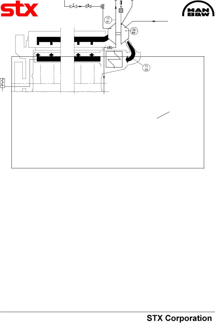
Water washing, turbine side, inlet P7 |
Exhaust gas, outlet P2 M1 Charge air, inlet |
|
P8 Water washing, |
|
compressor side with |
|
quick coupling, inlet |
Charging air from TC
Water washing compressor side
Exhaust gas to TC
Lambda Cylinder |
P6 Drain from turbocharger, outlet |
Fig. 1. Diagram for Turbocharger System
Turbocharger System
The turbocharger system of the engine, which is a constant pressure system, consists of an exhaust gas receiver, a turbocharger, a charging air cooler and a charging air receiver, the latter being integrated in the engine frame.
The turbine wheel of the turbocharger is driven by the engine exhaust gas, and the turbine wheel dri-ves the turbocharger compressor, which is moun-ted on the same shaft. The compressor sucks air from the engine room, through the air filters.
Turbocharger, see separate manual.
The turbocharger pumps the air through the charging air cooler to the charging air receiver. From the charging air receiver, the air flows to each cylinder, through the inlet valves.
The charging air cooler is a compact tube-type cooler with a large cooling surface. The cooling wa-ter is passed twice through the cooler, the end covers being designed with partitions which cause the cooling water to turn.
The cooling water tubes are fixed to the tube plates by expansion.
From the exhaust valves, the exhaust is led through a water cooled intermediate piece to the exhaust gas receiver where the pulsatory pressure from the individual exhaust valves is equalized and passed to the turbocharger as a constant pressure, and further to the exhaust outlet and silencer arrangement.
The exhaust gas receiver is made of pipe sections, one for each cylinder, connected to each other, by means of compensators, to prevent excessive stress in the pipes due to heat expansion.
95.26 - ES0S

512.01 |
Turbocharger System |
Description |
|
Edition 01H |
Page 2 (2) |
||
|
|||
|
|
||
L23/30H |
|
|
In the cooled intermediate piece a thermometer for reading the exhaust gas temperature is fitted and there is also possibility of fitting a sensor for remote reading.
To avoid excessive thermal loss and to ensure a reasonably low surface temperature the exhaust gas receiver is insulated.
95.26 - ES0S
Description |
Cleaning the Turbocharger In Service |
512.05 |
Page 1 (1) |
Water Washing of Compressor |
Edition 01H |
Compressor
Fouling of the airways depends primarily on the purity of the inlet air and thus, in turn, on the general maintenance condition of the machinery, i.e. mainly of the gas and oil tightness of the engines and on the fresh air ventilation system of the engine room.
Fouling of air filter, compressor or charging air cooler may be observed as changes in performance parameters:
-Decreasing charging air pressure.
-Decreasing turbocharger rotor speed.
-Increasing exhaust gas temperature.
-Severe fouling of airways may even result in compressor surge.
Regular cleaning during operation by injection of water before the compressor wheel will reduce the fouling rate considerably, and consequently prolong the intervals between dismantling necessary for mechanical cleaning.
L23/30H
Chemical cleaning will not improve the cleaning process as this primarily is based on the mechanical effect from the impact of the water droplets.
Certain types of fluid solvents can give formation of deposits on the compressor wheel, and should under no circumstances be used.
The intervals between cleaning by injection of water should be adjusted after assessing the degree and rate of fouling in the particular plant, i.e. based on observations and experience.
94.26 - ES0U-G

Description |
Cleaning the Turbocharger in Service |
512.15 |
Page 1 (1) |
Water Washing - Turbine Side |
Edition 01H |
L23/30H
Description
The tendency to fouling on the gas side of turbochargers depends on the combustion conditions, which are a result of the load on and the maintenance condition of the engine as well as the quality of the fuel oil used.
Fouling of the gas ways will cause higher exhaust gas temperatures and higher surface temperatures of the combustion chamber components and will also lead to a lower performance.
Tests and practical experience have shown that radial-flow turbines can be successfully cleaned by injection water into the inlet pipe of the turbine. The cleaning effect is based on the water solubility of the deposits and on the mechanical action of the impinging water droplets and the water flow rate.
The necessary water flow is dependent on the gas flow and the gas temperature. Enough water must be injected per time unit so that, not the entire flow will evaporate, but about 0.25 l/min. will flow off through the drainage opening in the gas outlet. Thus ensuring that sufficient water has been injected.
Service experience has shown that the above mentioned water flow gives the optimal cleaning effect. If the water flow is reduced the cleaning effect will be reduced or disappear. If the recommended water flow is exceed, there is a certain risk of a accumulation of water in the turbine casing, which can result in damage on the turbocharger.
The best cleaning effect is obtained by cleaning at low engine load approx. 20% MCR. Cleaning at low load will also reduce temperature shocks.
Experience has shown, that washing at regular intervals is essential to successful cleaning, as excessive fouling is thus avoided. Washing at intervals of 100 hours is therefore recommended. Depending on the fuel quality these intervals can be shorter or longer. However, the turbine must be washed at the latest when the exhaust gas temperature upstream of the turbine has risen about 20° C above the normal temperature.
Heavily contaminated turbines, which where not cleaned periodically from the very beginning or after an overhaul, cannot be cleaned by this method.
If vibration in the turbocharger occur after waterwashing has been carried out, the washing should be repeated. If unbalance still exists, this is presumably due to heavy fouling, and the engine must be stopped and the turbocharger dismantled and manually cleaned.
The washing water should be taken from the fresh water system and not from the fresh cooling water system or salt water system. No cleaning agents and solvents need to be added to the water.
To avoid corrosion during standstill, the engine must, upon completing of water washing run for at least 1 hour before stop so that all parts are dry.
Water Washing System
The water washing system consists of a pipe system equipped with a regulating valve, a manoeuvring valve, a 3-way cock and a drain pipe with a drain valve from the gas outlet, see illustration on working card 512-15.00.
The water for washing the turbine, is supplied from the external fresh water system through a flexible hose with couplings. The flexible hose must be disconnected after water washing.
By activating the manoeuvring valve and the regulating valve, water is led through the 3-way cock to the exhaust pipe intermediate flange, equipped with a channel to lead the water to the gas inlet of the turbocharger.
The water which is not evaporated, is led out through the drain pipe in the gas outlet.
96.39 - ES0U-G