

- •500 Engine Data
- •500.00 Main Data for GenSets
- •500.01(01H) Introduction
- •500.02(01H) Safety
- •500.05(01H) Cross Section
- •500.10(01H) Key for Engine Designation
- •500.11(01H) Designation of Cylinders
- •500.12(01H) Engine Rotation Clockwise
- •500.20(01H) Code identification for Instruments
- •500.35(01H) Data for Pressure and Tolerance
- •500.35(11H) Data for Pressure and Tolerance
- •500.40(01S) Data for Torque Moment
- •500.45(01H) Declaration of Weight
- •500.50(01H) Ordering of Spare Parts
- •500.55(01H) Service Letters
- •500.60(01H) Conversion Table
- •500.65(01H) Basic Symbols for Piping
- •501 Operation of Engine
- •501.01(01H) Operating
- •501.05(01H) Out-of Service
- •501.10(01H) Starting-up after Out of Service Periods
- •501.15(02H) Guidelines for Longterm Low-Load Operation on HFO
- •501.25(01H) Operating a Diesel Engine at Low Frequency
- •502 Engine Performance and Condition
- •502.01(01H) Engine Performance and Condition
- •502.05(01H) Condensate Amount
- •502-01.00(01H) Engine Performance Data
- •503 Trouble Tracing
- •503.01(01H) Starting Failures
- •503.01(02H) Starting Failures
- •503.02(01H) Faults in Fuel Oil System
- •503.03(01H) Disturbances during Running
- •503.04(01H) Ignition in Crankcase
- •503.06(01H) Trouble Shooting Guide for Turbine Starter
- •503.09(01H) Trouble Shooting for Cooling Water System
- •503.10(01H) Trouble Shooting for Lubricating Oil Cooler
- •504.01(01H) Lubricating Oil Specification
- •504.01(05H) Lubricating Oil Specification
- •504.03(01H) Maintenance of Lubricating Oil Condition
- •504.05(01H) Lubricating Points
- •504.06(01H) Lubricating Oil in Base Frame
- •504.06(04H) Lubricating Oil in Base Frame
- •504.20(02H) Fuel Oil Specification
- •504.20(04H) Fuel Oil Specification
- •504.25(01H) Fuel Oil Quality
- •504.26(01H) Nomogram for Determination of CCAI
- •504.26(02H) Nomogram for Determination of CCAI
- •504.27(01H) Analysis Data
- •504.30(01H) Fuel Oil Cleaning
- •504.40(01H) Fresh Water System Treatment
- •504.40(02H) Freshwater System Treatment
- •505 Cylinder Head
- •505.01(01H) Cylinder Head
- •505-01.00(01H) Dismantling of Cylinder Head
- •505-01.05(01H) Inspection of Inlet Valve, Exhaust Valve and Valve Guide
- •505-01.15(01H) Valve Rotator
- •505-01.20(01H) Replacement of Valve Guide
- •505-01.26(01H) Indicator Valve
- •505-01.30(01H) Replacement of Sleeve for Fuel Injector
- •505-01.35(01H) Replacement of Valve Seat Ring
- •505-01.40(01H) Mounting of Cylinder Head
- •505-01.45(01H) Inspection of Cylinder Head Cooling Water Space
- •50501-01H Cylinder Head
- •50502-01H Valve Spindles and Valve Gear
- •50508-01H Indicator Valve
- •50510-01H Cylinder Head, Top Cover
- •506 Piston, Connecting Rod and Cylinder Liner
- •506.01(01H) Piston, Connecting Rod and Cylinder liner
- •506-01.05(01H) Separation of Piston and Connecting Rod
- •506-01.10(01H) Piston
- •506-01.15(01H) Connecting Rod
- •506-01.25(01H) Tightening and Check of Connecting Rod Screws
- •506-01.30(01H) In-situ Inspection of Connecting Rod Big-end Bearing
- •506-01.35(01H) Inspection and Honing of Cylinder Liner
- •506-01.40(01H) Replacement of Cylinder Liner
- •50601-01H Piston and Connecting Rod
- •507 Camshaft and Camshaft Drive
- •507.01(01H) Camshaft and Camshaft Drive
- •507-01.00(01H) Check of Camshaft and Camshaft Drive
- •507-01.05(01H) Inspection and Replacement of Camshaft Bearing
- •507-01.20(01H) Adjustment of Camshaft
- •50701-01H Intermediate Wheel
- •50705-01H Camshaft and Camshaft Bearing
- •50705-07H Camshaft and Camshaft Bearing
- •508-01.00(01S) Inspection of Valve Roller Guides
- •50801-01H Roller Guide and Push Rods
- •509.01(01H) Control and Safety Systems
- •509.05(01H) Instruments and Automatics
- •509.10(02H) Lambda Controller
- •509.35(01H) Starting Box
- •509-01.05(01H) Functional Test and Adjustment of Overspeed Trip
- •509-05.00(01S) Adjustment and Test of ON/OFF Pressostate
- •509-05.01(01S) Adjustment and Test of ON/OFF Thermostate
- •50903-01H Overspeed Device
- •50905-03H Prelubricating Oil Alarm (LAL 25)
- •50905-04H Instrument Panel
- •50907-02H Thermometer
- •50908-01H Pick-up
- •50910-01H Lambda Controller
- •50935-01H Starting Box
- •510 Crankshaft and Main Bearings
- •510.01(01H) Crankshaft and Main Bearings
- •510-01.00(05H) Checking of Main Bearings Alignment (Autolog)
- •510-01.05(01H) Inspection of Main Bearing Shells
- •510-01.10(01H) Inspection of Guide Bearing Shells
- •51001-01H Crankshaft
- •51002-02H Resilient Gear Wheel
- •51003-02H Flywheel with Gear Rim
- •511S Engine Frame and Base Frame
- •511.01(01H) Engine Frame and Base Frame
- •511-01.00(01H) Functional Test of Crankcase Safety Relief Valves
- •51101-02H Frame with Main Bearings
- •51102-02H Mounting of Pumps
- •51106-02H Covers on Frame
- •51106-03S Covers on Frame
- •512 Turbocharger System
- •512.01(01H) Turbocharger System
- •512-01.00(01H) Overhaul of Charging Air Cooler
- •512-15.00(01H) Water Washing of Turbine Side
- •51202-01S Exhaust Pipe Arrangement
- •51203-03H Turbocharging Arrangement
- •513 Compressed Air System
- •513.01(01S) Compressed Air System
- •513.01.30(01H) Overhaul, Test and Inspection of Turbine Starter
- •513-01.40(01H) Main Starting Valve
- •513-01.90(01H) Check of Compressed Air Piping System
- •51309-01H Turbine Starter
- •51310-01H Main Starting Valve
- •51314-01S Starting Valve
- •51315-03H Main Stop Valve
- •51316-03H Air Strainer
- •51319-02H Safety Valve
- •51320-01H ON-OFF Valve for Jet System
- •51321-01H Air Filter
- •514 Fuel Oil System
- •514.01(01H) Internal Fuel Oil System
- •514-01.05(01H) Fuel Injection Pump and Fuel Injection Pipe
- •514-01.10(02H) Fuel Injection Valve
- •514-01.15(01H) Fuel Oil Split Filter
- •514-01.90(01H) Check of Fuel Oil Piping System
- •514-05.01(01H) Adjustment of The Maximum Combustion Pressure
- •51401-01H Fuel Injection Pump
- •51402-01H Fuel Injection Valve
- •51403-01H Fuel Oil Filter Duplex
- •51404-01H Fuel Injection Pipe
- •51430-01H Pipes on Cylinder Section
- •515 Lubricating Oil System
- •515.01(01H) Internal Lubricating Oil System
- •515.06(01H) Lubricating Oil Cooler
- •515-01.00(01H) Lubricating Oil Pump, Engine Driven
- •515-01.10(01H) Lubricating Oil Filter
- •515-01.20(01H) Lubricating Oil, Thermostatic Valve
- •515-01.90(01H) Check of Lubricating Oil Piping System
- •515-06.00(02H) Lubricating Oil Cooler
- •51501-03H Lubricating Oil Pump (Gear Driven)
- •51502-01H Lubricating Oil Filter (Type A)
- •51502-02H Lubricating Oil Filter (Suppl. for Plate 51502-01H)
- •51504-01H Prelubricating Pump
- •51506-01H Lubricating Oil Cooler
- •51525-01H Hand Wing Pump
- •51530-01H Lubricating Oil Separator
- •516 Cooling Water System
- •516.01(01H) Cooling Water System
- •516.04(01H) Cooling Water Thermostatic Valve
- •516-01.90(01H) Check of Cooling Water System
- •516.04-00(01H) Cooling Water, Thermostatic Valve
- •51604-01H Cooling Water Thermostatic Valve
- •51610-01H High Temperature Fresh Water Pump
- •51625-01H Pipes on Cylinder Head
- •51635-01H Preheater - Fresh Water
- •517 Special Equipment
- •518 Driven Machinery
- •519 Specific Plant Information
- •519.03(01S) Resilient Mounting of Generating Sets
- •519-03.00(01S) Fitting Instructions for Resilient Mounting of GenSets
- •519-03.00(02S) Fitting Instructions for Resilient Mounting of GenSets
- •519-03.00(03S) Fitting Instructions for Resilient Mounting of GenSets
- •519-03.05(01S) Replacement of Conicals
- •519-03.10(01S) Replacement of Conicals
- •520 Tools
- •520.01(01H) Introduction to Spare Part Plates for Tools
- •520-01.05(01H) Application of Hydraulic Tools
- •520-01.10(01H) Maintenance of Hydraulic Tools
- •520-01.15(01H) Tightening with Torque Spanner

Index
Page 1 (1)
Crankshaft and Main Bearings |
510 |
|
|
|
L23/30H |
Description |
|
Crankshaft and Main Bearings ........................................................................................ |
510.01 (01H) |
Working Card |
|
Checking of Main Bearings Alignment (Autolog) ....................................................... |
510-01.00 (01H) |
Inspection of Main Bearing Shells ............................................................................. |
510-01.05 (01H) |
Inspection of Guide Bearing Shells ............................................................................ |
510-01.10 (01H) |
Vibration Damper ....................................................................................................... |
510-04.00 (01H) |
Plates |
|
Crankshaft .......................................................................................................................... |
51001-04H |
Coupling for Central Driven Lub. Oil Pump ......................................................................... |
51002-01H |
Resilient Gear Wheel .......................................................................................................... |
51002-02H |
Flywheel with Flexible Coupling and Gear Rim .................................................................. |
51003-01H |
Flywheel with Gear Rim ...................................................................................................... |
51003-02H |
Flywheel with Gear Rim ...................................................................................................... |
51003-03H |
Torsional Vibration Damper ................................................................................................ |
51004-01H |
Tuning Wheel ...................................................................................................................... |
51004-02H |
08028-0D/H5250/94.08.12
98.35 - ES0U

Description |
Crankshaft and Main Bearings |
510.01 |
Page 1 (1) |
Edition 01H |
|
|
|
|
|
|
|
|
|
L23/30H |
Crankshaft |
Vibration Damper |
|
The crankshaft, which is a one-piece forging with ground main bearing and crankpin journals, is suspended in inderslung bearings. The main bearings are equipped with insertion-type shells, which are coated with a wearing surface. To attain a suitable bearing pressure the crankshaft is provided with counterweights, which are attached to the crankshaft by means of two screws.
At the flywheel end the crankshaft is fitted with a gear wheel which through an intermediate wheel drives the camshaft. Also fitted here is the flywheel and a coupling flange for connection of a reduction gear or an alternator. At the opposite end there is a claw-type coupling for the lub. oil pump or a flexible gear wheel connection for lub. oil and water pumps.
In special cases a vibration damper is mounted on the crankshaft to limit torsional vibrations. The damper consists essentially of a heavy flywheel totally enclosed in a light casing. A small clearance is allowed between the casing and the flywheel, and this space is filled with a highly viscous fluid. The casing is rigidly connected to the front end of the engine crankshaft and the only connection between the crankshaft and the damper flywheel is through the fluid. Under conditions of no vibration, the casing and damper flywheel tend to rotate as one unit, since the force required to sheartheviscousfilmisconsi-derable.Asthetorsional vibration amplitudes increase, the casing follows the movement of the crankshaft but the flywheel tends to rotate uniformly by virtue of its inertia, and relative motion occurs between the flywheel and the casing. The viscous fluid film therefore undergoes a shearing action, and vibration energy is absorbed and appears as heat.
08028-0D/H5250/94.08.12
96.03 - ES0U
Working Card |
Checking of Main Bearings Alignment (Autolog) |
510-01.00 |
Page 1 (6) |
Edition 01H |
|
|
|
|
|
|
|
|
|
L23/30H |
08028-0D/H5250/94.08.12
Safety precautions: |
Special tools: |
|
|
||
|
|
Stopped engine |
Plate no. |
Item no. |
Note |
|
|||||
|
|
Shut-off starting air |
|
|
|
|
|
|
|
|
|
|
|
Shut-off cooling water |
52010 |
011 |
|
|
|
Shut-off fuel oil |
52010 |
059 |
|
|
|
Shut-off cooling oil |
|
|
|
|
|
Stopped lub. oil circul. |
|
|
|
|
|
|
|
||
Description:
Checking of main bearings alignment (autolog).
Hand tools:
Starting position:
Turning gear in engagement. (If mounted). Cover for crankshaft has been removed from frame.
All indicator valves open.
Related procedure:
Manpower: |
|
|
|
Replacement and wearing parts: |
||
Working time |
: |
1 1/2 |
hours |
Plate no |
Item no |
Qty / |
Capacity |
: |
2 |
men |
|
|
|
Data: |
|
|
|
|
|
|
Data for pressure and tolerance |
(Page 500.35) |
|
|
|||
Data for torque moment |
|
(Page 500.40) |
|
|
||
Declaration of weight |
|
(Page 500.45) |
|
|
||
95.50 - ES0S-G
510-01.00 |
Checking of Main Bearings Alignment (Autolog) |
Working Card |
Edition 01H |
Page 2 (6) |
|
|
|
|
|
|
|
L23/30H |
|
|
Alignment of Main Bearings.
The lower main bearing shells should be positioned so that they keep the main bearing journals of the crankshaft centered in a straight (ashore horizontal) line. Deviations from this centre line cause the crankshaft to bend and increase the load on some main bearings.
If two adjacent main bearings are placed too low, the crankshaft centre line will in this place be lowered to form an arc, causing the intermediate crank throw to bend in such a way that it "closes" when turned into bottom position and "opens" in top position.
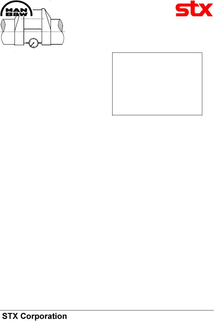
Fig 1. Placing of dial gauge.
As the magnitude of such axial lengthening and shortening during the turning of the throw increases in proportion to the difference in the height of the bearing, it is measured as a check on the alignment and condition of the bearing.
As the crankshafts of medium speed engines are very stiff, any great deviations in the alignment will result in clearance at the bottom shell of the bearings.
The cause of incorrect main bearing position may be wear of the bearings or misalignmnet of the engine.
Effecting The Deflection Measurement.
The deflection measurement is effected by placing a springloaded dial gauge in the centre punch marks provided for this purpose, see fig. 1.
"Closing" of the throw in top dead centre is regarded as negative, (compression of the gauge).
In the example, page 3, the deflection reading is therefore negative.
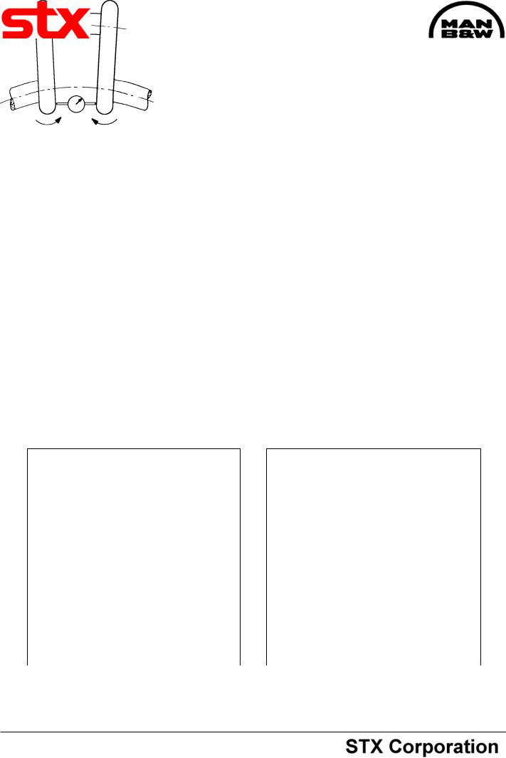
As during the turning of the throw, the gauge and the connecting rod will meet near the bottom position of the throw, the measurement for the bottom position is to be replaced by the average of the two near by positions on either side.
The dial gauge is set to zero, when the crank throw is in the near-bottom (x in fig. 8) and during the turning the throw is stopped in the position horizontal-top- horizontal-near bottom (P-T-S-Y in fig. 8) for reading of the gauge.
Checking The Deflection Measurement.
The reading is entered in the table page 6, see example in fig. 2 - 6.
As "bottom" reading is used the mean value of the two "near bottom" readings X and Y, fig. 3.
The total deflection ("opening-closing") of the throw during the turning from bottom to top position is entered in fig. 4.
These figures are due to vertical misalignment of the main bearings.
Similarly, horizontal misalignment procedures the figures in the table fig. 5.
Besides misalignment of the bearings, the readings can be influenced by ovality or eccentricity of the journals.
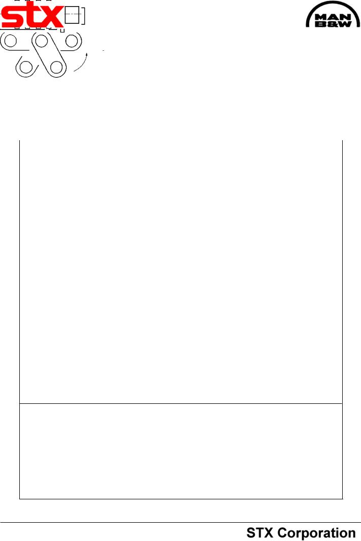
Engines Equipped with Turning Gear.
When taking these deflection readings for the three aftmost cylinders, the turning gear should at each stoppage be turned a little backwards to ease off the tangential pressure on the teeth of the turning wheel as this pressure may otherwise falsify the readings.
08028-0D/H5250/94.08.12
95.50 - ES0S-G
Working Card |
Checking of Main Bearings Alignment (Autolog) |
510-01.00 |
Page 3 (6) |
Edition 01H |
|
|
|
|
|
|
|
Deflection of crankshaft in 1/100 mm. (0.01 mm).
|
|
|
|
Cyl. No. |
|
|
|
Crank position |
|
1 |
2 |
3 |
4 |
5 |
6 |
|
|
|
|
|
|
|
|
Bottom start |
X |
0 |
0 |
0 |
0 |
0 |
0 |
Left side |
P |
2 |
0 |
2 |
0 |
-1 |
2 |
Top |
T |
3 |
-2 |
4 |
5 |
-2 |
3 |
Right side |
S |
3 |
-2 |
2 |
0 |
0 |
1 |
Bottom stop |
Y |
2 |
-1 |
0 |
1 |
0 |
2 |
|
|
|
|
|
|
|
|
Fig 2. |
|
|
|
|
|
|
|
|
|
|
|
|
|
|
|
Bottom (0,5 x Y) = |
B |
1 |
-0.5 |
0 |
+0.5 |
0 |
1 |
|
|
|
|
|
|
|
|
Fig 3. |
|
|
|
|
|
|
|
L23/30H
Deflection from vertical |
|
|
|
|
|
|
|
misalignment |
|
|
|
|
|
|
|
top - bottom |
|
|
|
|
|
|
|
or T - B = |
V |
2 |
-1.5 |
4 |
4.5 |
-2 |
2 |
|
|
|
|
|
|
|
|
Fig 4. |
|
|
|
|
|
|
|
|
|
|
|
|
|
|
|
Deflection from hori- |
|
|
|
|
|
|
|
zontal misalignment |
|
|
|
|
|
|
|
Left side - right side |
|
|
|
|
|
|
|
or P - S = |
H |
-1 |
-2 |
0 |
0 |
-1 |
1 |
|
|
|
|
|
|
|
|
Fig 5. |
|
|
|
|
|
|
|
|
|
|
|
|
|
|
|
Check on |
T + B = C |
4 |
-2.5 |
4 |
5.5 |
-2 |
4 |
gauge |
|
|
|
|
|
|
|
readings |
P + S = D |
5 |
-2 |
4 |
0 |
-1 |
3 |
|
|
|
|
|
|
|
|
Fig 6.
C and D should be nearly the same, reading for cylinder 4 to be repeated.
08028-0D/H5250/94.08.12
T
S
|
|
Front end view. |
"Closing" of the crankthrow is considered ne- |
Start in position X. |
|
gative. |
Turn anti clockwise |
|
|
|
|
Fig 7. |
Fig 8. |
|
95.50 - ES0S-G

510-01.00 |
Checking of Main Bearings Alignment (Autolog) |
Working Card |
Edition 01H |
Page 4 (6) |
|
|
|
|
|
|
|
L23/30H |
|
|
Measurement of Crank Throw Deflections by Means of Dial Indicator (Autolog)
Crank throw deflection |
= |
Difference in dial indicator readings in two diametrically |
|
|
opposite crank throw positions, i.e. two positions dis- |
|
|
placed 180°. |
Vertical deflection |
= |
Difference in top-bottom readings. |
Horizontal deflection |
= |
Difference in side-side readings. |
Vertical og Horizontal Deflections of Crank Throws
Unless otherwise stated the values refer to cold engine.
For new or realigned aggregate |
Aim for |
+ or - 3/100 |
mm |
|
Acceptable |
+ or - 5/100 |
mm |
For aggregate in service realignment |
|
|
|
is recommended if deflections exceed |
|
+ or - 8/100 |
mm |
Vertical Deflection of Crank Throw at Flywheel
Unless otherwise stated the values refer to cold engine.
Rigid coupling between |
|
|
Flexible coupling between |
|
|
||
diesel engine and driven machine |
diesel engine and driven machine |
||||||
For new or realigned |
|
|
|
For new or realigned |
|
|
|
aggregate |
0 to |
+ |
3/100 mm |
aggregate |
Aim for |
- 6/100 mm |
|
|
|
|
|
|
Acceptable |
- 8/100 mm |
|
For aggregate in service realignment is |
For aggregate in service |
|
|
||||
recommended if deflection measured |
realignment recommendable |
|
|
||||
on warm engine exceeds |
- |
8/100 mm |
if deflection exceeds |
- 12/100 mm |
|||
|
|
|
|
|
|
|
|
08028-0D/H5250/94.08.12
95.50 - ES0S
Working Card |
|
Checking of Main Bearings Alignment (Autolog) |
510-01.00 |
||||
Page 5 (6) |
|
Edition 01H |
|||||
|
|
|
|
|
|
||
|
|
|
|
|
|
|
|
|
|
|
|
|
|
L23/30H |
|
|
|
|
|
|
|
|
|
|
Process/Proces |
|
|
I.D. no. |
|
|
|
|
|
|
|
|
|
||
|
Plant/Anlæg |
|
|
Page of/Side af |
|
||
|
|
|
|
|
|
||
|
Engine Type/Motortype |
Engineer/Operatør |
Date/Dato |
|
|
||
|
|
|
|
|
|
||
|
|
|
|
|
|
||
|
Instruction/Instruktion |
|
|
|
|
||
Top
Right side
1/100 mm
Bottom end/ |
Bottom start/ |
Bund slut |
Bund start |
|
Right side |
|
Right side |
Cyl. no |
1 2 3 |
Cyl. no |
1 2 3 |
Left side |
Cyl. no |
1 2 3 |
|
|
Left side |
Remarks/Bemærkninger
08028-0D/H5250/94.08.12
95.50 - ES0S-G

510-01.00 |
|
Checking of Main Bearings Alignment (Autolog) |
|
|
Working Card |
|
|||||||||||||
Edition 01H |
|
|
|
Page 6 (6) |
|
||||||||||||||
|
|
|
|
|
|
|
|
|
|
|
|
|
|
|
|
|
|
||
|
|
|
|
|
|
|
|
|
|
|
|
|
|
|
|
|
|
|
|
L23/30H |
|
|
|
|
|
|
|
|
|
|
|
|
|
|
|
|
|
|
|
|
|
|
|
|
|
|
|
|
|
|
|
|
|
|
|
|
|
||
|
Component/Komponent |
|
|
|
|
|
Type |
|
|
I.D. no. |
|
|
|
||||||
|
|
|
|
|
|
|
|
|
|
|
|
|
|
|
|
|
|
||
|
Process/Proces |
|
|
|
|
|
|
|
|
|
|
Page of/Side af |
|
|
|
||||
|
|
|
|
|
|
|
|
|
|
|
|
|
|
|
|
|
|
|
|
|
|
|
|
|
|
|
|
|
|
|
|
|
|
|
|
|
|
|
|
|
Test place/ |
|
|
Test bed/prøvehal |
|
Cold/Kold |
|
|
|
|
|
|
|
|
|
||||
|
Condition |
|
|
|
|
|
|
|
|
|
|
|
|
|
|
|
|
|
|
|
|
|
|
On board/Om bord |
|
Warm/Varm |
|
|
|
|
|
|
|
|
|
||||
|
Teststed/ |
|
|
|
|
|
|
|
|
|
|
|
|
|
|
|
|
|
|
|
Tilstand |
|
|
Plant/Maskinhal |
|
|
|
|
|
|
|
|
|
|
|
|
|
|
|
|
|
|
|
|
|
|
|
|
|
|
|
|
|
|
|
|
|
|
|
|
Engine no.: |
|
|
|
|
|
|
|
|
|
|
|
|
|
|
|
|
|
|
|
Motornr.: |
|
|
|
|
|
|
|
|
|
|
|
|
|
|
|
|
|
|
|
|
|
|
|
|
|
|
|
|
|
|
|
|
|
|
|
|
|
|
|
Cyl. no. |
|
1 |
2 |
|
3 |
4 |
5 |
|
|
6 |
7 |
|
8 |
|
|
9 |
|
|
|
|
|
|
|
|
|
|
|
|
|
|
|
|
|
|
|
|
|
|
|
Bottom |
X |
0 |
0 |
|
0 |
0 |
0 |
|
|
0 |
0 |
|
0 |
|
|
0 |
|
|
|
|
|
|
|
|
|
|
|
|
|
|
|
|
|
|
|
|
|
|
|
Left side |
P |
|
|
|
|
|
|
|
|
|
|
|
|
|
|
|
|
|
|
|
|
|
|
|
|
|
|
|
|
|
|
|
|
|
|
|
|
|
|
Top |
T |
|
|
|
|
|
|
|
|
|
|
|
|
|
|
|
|
|
|
|
|
|
|
|
|
|
|
|
|
|
|
|
|
|
|
|
|
|
|
Right side |
S |
|
|
|
|
|
|
|
|
|
|
|
|
|
|
|
|
|
|
|
|
|
|
|
|
|
|
|
|
|
|
|
|
|
|
|
|
|
|
Bottom |
Y |
|
|
|
|
|
|
|
|
|
|
|
|
|
|
|
|
|
|
|
|
|
|
|
|
|
|
|
|
|
|
|
|
|
|
|
|
|
|
|
|
|
|
|
|
|
|
|
|
|
|
|
|
|
|
|
|
|
|
Bottom |
|
|
|
|
|
|
|
|
|
|
|
|
|
|
|
|
|
|
|
(0.5xY)=B |
|
|
|
|
|
|
|
|
|
|
|
|
|
|
|
|
|
|
|
|
|
|
|
|
|
|
|
|
|
|
|
|
|
|
|
|
|
|
|
|
|
|
|
|
|
|
|
|
|
|
|
|
|
|
|
|
|
|
|
Deflection from |
|
|
|
|
|
|
|
|
|
|
|
|
|
|
|
|
|
|
|
vertical misalign- |
|
|
|
|
|
|
|
|
|
|
|
|
|
|
|
|
|
|
|
ment. |
|
|
|
|
|
|
|
|
|
|
|
|
|
|
|
|
|
|
|
Top - bottom |
|
|
|
|
|
|
|
|
|
|
|
|
|
|
|
|
|
|
|
or T - B = |
V |
|
|
|
|
|
|
|
|
|
|
|
|
|
|
|
|
|
|
|
|
|
|
|
|
|
|
|
|
|
|
|
|
|
|
|
|
|
|
|
|
|
|
|
|
|
|
|
|
|
|
|
|
|
|
|
|
|
|
Deflection from |
|
|
|
|
|
|
|
|
|
|
|
|
|
|
|
|
|
|
|
horizontal mis- |
|
|
|
|
|
|
|
|
|
|
|
|
|
|
|
|
|
|
|
alignment. |
|
|
|
|
|
|
|
|
|
|
|
|
|
|
|
|
|
|
|
Left side - Right |
|
|
|
|
|
|
|
|
|
|
|
|
|
|
|
|
0D/H5250/94.08.12-08028 |
|
|
side or P - S = H |
|
|
|
|
|
|
|
|
|
|
|
|
|
|
|
|
||
|
|
|
|
|
|
|
|
|
|
|
|
|
|
|
|
|
|
||
|
|
|
|
|
|
|
|
|
|
|
|
|
|
|
|
|
|
|
|
|
|
|
|
|
|
|
|
|
|
|
|
|
|
|
|
|
|
|
|
|
Check on gauge |
|
|
|
|
|
|
|
|
|
|
|
|
|
|
|
|
|
|
|
readings. |
|
|
|
|
|
|
|
|
|
|
|
|
|
|
|
|
|
|
|
T + B = |
C |
|
|
|
|
|
|
|
|
|
|
|
|
|
|
|
|
|
|
|
|
|
|
|
|
|
|
|
|
|
|
|
|
|
|
|
|
|
|
P + S = |
D |
|
|
|
|
|
|
|
|
|
|
|
|
|
|
|
|
|
|
|
|
|
|
|
|
|
|
|
|
|
|
|
|
|
|
|
|
|
95.50 - ES0S-G