

- •500 Engine Data
- •500.00 Main Data for GenSets
- •500.01(01H) Introduction
- •500.02(01H) Safety
- •500.05(01H) Cross Section
- •500.10(01H) Key for Engine Designation
- •500.11(01H) Designation of Cylinders
- •500.12(01H) Engine Rotation Clockwise
- •500.20(01H) Code identification for Instruments
- •500.35(01H) Data for Pressure and Tolerance
- •500.35(11H) Data for Pressure and Tolerance
- •500.40(01S) Data for Torque Moment
- •500.45(01H) Declaration of Weight
- •500.50(01H) Ordering of Spare Parts
- •500.55(01H) Service Letters
- •500.60(01H) Conversion Table
- •500.65(01H) Basic Symbols for Piping
- •501 Operation of Engine
- •501.01(01H) Operating
- •501.05(01H) Out-of Service
- •501.10(01H) Starting-up after Out of Service Periods
- •501.15(02H) Guidelines for Longterm Low-Load Operation on HFO
- •501.25(01H) Operating a Diesel Engine at Low Frequency
- •502 Engine Performance and Condition
- •502.01(01H) Engine Performance and Condition
- •502.05(01H) Condensate Amount
- •502-01.00(01H) Engine Performance Data
- •503 Trouble Tracing
- •503.01(01H) Starting Failures
- •503.01(02H) Starting Failures
- •503.02(01H) Faults in Fuel Oil System
- •503.03(01H) Disturbances during Running
- •503.04(01H) Ignition in Crankcase
- •503.06(01H) Trouble Shooting Guide for Turbine Starter
- •503.09(01H) Trouble Shooting for Cooling Water System
- •503.10(01H) Trouble Shooting for Lubricating Oil Cooler
- •504.01(01H) Lubricating Oil Specification
- •504.01(05H) Lubricating Oil Specification
- •504.03(01H) Maintenance of Lubricating Oil Condition
- •504.05(01H) Lubricating Points
- •504.06(01H) Lubricating Oil in Base Frame
- •504.06(04H) Lubricating Oil in Base Frame
- •504.20(02H) Fuel Oil Specification
- •504.20(04H) Fuel Oil Specification
- •504.25(01H) Fuel Oil Quality
- •504.26(01H) Nomogram for Determination of CCAI
- •504.26(02H) Nomogram for Determination of CCAI
- •504.27(01H) Analysis Data
- •504.30(01H) Fuel Oil Cleaning
- •504.40(01H) Fresh Water System Treatment
- •504.40(02H) Freshwater System Treatment
- •505 Cylinder Head
- •505.01(01H) Cylinder Head
- •505-01.00(01H) Dismantling of Cylinder Head
- •505-01.05(01H) Inspection of Inlet Valve, Exhaust Valve and Valve Guide
- •505-01.15(01H) Valve Rotator
- •505-01.20(01H) Replacement of Valve Guide
- •505-01.26(01H) Indicator Valve
- •505-01.30(01H) Replacement of Sleeve for Fuel Injector
- •505-01.35(01H) Replacement of Valve Seat Ring
- •505-01.40(01H) Mounting of Cylinder Head
- •505-01.45(01H) Inspection of Cylinder Head Cooling Water Space
- •50501-01H Cylinder Head
- •50502-01H Valve Spindles and Valve Gear
- •50508-01H Indicator Valve
- •50510-01H Cylinder Head, Top Cover
- •506 Piston, Connecting Rod and Cylinder Liner
- •506.01(01H) Piston, Connecting Rod and Cylinder liner
- •506-01.05(01H) Separation of Piston and Connecting Rod
- •506-01.10(01H) Piston
- •506-01.15(01H) Connecting Rod
- •506-01.25(01H) Tightening and Check of Connecting Rod Screws
- •506-01.30(01H) In-situ Inspection of Connecting Rod Big-end Bearing
- •506-01.35(01H) Inspection and Honing of Cylinder Liner
- •506-01.40(01H) Replacement of Cylinder Liner
- •50601-01H Piston and Connecting Rod
- •507 Camshaft and Camshaft Drive
- •507.01(01H) Camshaft and Camshaft Drive
- •507-01.00(01H) Check of Camshaft and Camshaft Drive
- •507-01.05(01H) Inspection and Replacement of Camshaft Bearing
- •507-01.20(01H) Adjustment of Camshaft
- •50701-01H Intermediate Wheel
- •50705-01H Camshaft and Camshaft Bearing
- •50705-07H Camshaft and Camshaft Bearing
- •508-01.00(01S) Inspection of Valve Roller Guides
- •50801-01H Roller Guide and Push Rods
- •509.01(01H) Control and Safety Systems
- •509.05(01H) Instruments and Automatics
- •509.10(02H) Lambda Controller
- •509.35(01H) Starting Box
- •509-01.05(01H) Functional Test and Adjustment of Overspeed Trip
- •509-05.00(01S) Adjustment and Test of ON/OFF Pressostate
- •509-05.01(01S) Adjustment and Test of ON/OFF Thermostate
- •50903-01H Overspeed Device
- •50905-03H Prelubricating Oil Alarm (LAL 25)
- •50905-04H Instrument Panel
- •50907-02H Thermometer
- •50908-01H Pick-up
- •50910-01H Lambda Controller
- •50935-01H Starting Box
- •510 Crankshaft and Main Bearings
- •510.01(01H) Crankshaft and Main Bearings
- •510-01.00(05H) Checking of Main Bearings Alignment (Autolog)
- •510-01.05(01H) Inspection of Main Bearing Shells
- •510-01.10(01H) Inspection of Guide Bearing Shells
- •51001-01H Crankshaft
- •51002-02H Resilient Gear Wheel
- •51003-02H Flywheel with Gear Rim
- •511S Engine Frame and Base Frame
- •511.01(01H) Engine Frame and Base Frame
- •511-01.00(01H) Functional Test of Crankcase Safety Relief Valves
- •51101-02H Frame with Main Bearings
- •51102-02H Mounting of Pumps
- •51106-02H Covers on Frame
- •51106-03S Covers on Frame
- •512 Turbocharger System
- •512.01(01H) Turbocharger System
- •512-01.00(01H) Overhaul of Charging Air Cooler
- •512-15.00(01H) Water Washing of Turbine Side
- •51202-01S Exhaust Pipe Arrangement
- •51203-03H Turbocharging Arrangement
- •513 Compressed Air System
- •513.01(01S) Compressed Air System
- •513.01.30(01H) Overhaul, Test and Inspection of Turbine Starter
- •513-01.40(01H) Main Starting Valve
- •513-01.90(01H) Check of Compressed Air Piping System
- •51309-01H Turbine Starter
- •51310-01H Main Starting Valve
- •51314-01S Starting Valve
- •51315-03H Main Stop Valve
- •51316-03H Air Strainer
- •51319-02H Safety Valve
- •51320-01H ON-OFF Valve for Jet System
- •51321-01H Air Filter
- •514 Fuel Oil System
- •514.01(01H) Internal Fuel Oil System
- •514-01.05(01H) Fuel Injection Pump and Fuel Injection Pipe
- •514-01.10(02H) Fuel Injection Valve
- •514-01.15(01H) Fuel Oil Split Filter
- •514-01.90(01H) Check of Fuel Oil Piping System
- •514-05.01(01H) Adjustment of The Maximum Combustion Pressure
- •51401-01H Fuel Injection Pump
- •51402-01H Fuel Injection Valve
- •51403-01H Fuel Oil Filter Duplex
- •51404-01H Fuel Injection Pipe
- •51430-01H Pipes on Cylinder Section
- •515 Lubricating Oil System
- •515.01(01H) Internal Lubricating Oil System
- •515.06(01H) Lubricating Oil Cooler
- •515-01.00(01H) Lubricating Oil Pump, Engine Driven
- •515-01.10(01H) Lubricating Oil Filter
- •515-01.20(01H) Lubricating Oil, Thermostatic Valve
- •515-01.90(01H) Check of Lubricating Oil Piping System
- •515-06.00(02H) Lubricating Oil Cooler
- •51501-03H Lubricating Oil Pump (Gear Driven)
- •51502-01H Lubricating Oil Filter (Type A)
- •51502-02H Lubricating Oil Filter (Suppl. for Plate 51502-01H)
- •51504-01H Prelubricating Pump
- •51506-01H Lubricating Oil Cooler
- •51525-01H Hand Wing Pump
- •51530-01H Lubricating Oil Separator
- •516 Cooling Water System
- •516.01(01H) Cooling Water System
- •516.04(01H) Cooling Water Thermostatic Valve
- •516-01.90(01H) Check of Cooling Water System
- •516.04-00(01H) Cooling Water, Thermostatic Valve
- •51604-01H Cooling Water Thermostatic Valve
- •51610-01H High Temperature Fresh Water Pump
- •51625-01H Pipes on Cylinder Head
- •51635-01H Preheater - Fresh Water
- •517 Special Equipment
- •518 Driven Machinery
- •519 Specific Plant Information
- •519.03(01S) Resilient Mounting of Generating Sets
- •519-03.00(01S) Fitting Instructions for Resilient Mounting of GenSets
- •519-03.00(02S) Fitting Instructions for Resilient Mounting of GenSets
- •519-03.00(03S) Fitting Instructions for Resilient Mounting of GenSets
- •519-03.05(01S) Replacement of Conicals
- •519-03.10(01S) Replacement of Conicals
- •520 Tools
- •520.01(01H) Introduction to Spare Part Plates for Tools
- •520-01.05(01H) Application of Hydraulic Tools
- •520-01.10(01H) Maintenance of Hydraulic Tools
- •520-01.15(01H) Tightening with Torque Spanner

Working Card |
Tightening and Check of Connecting Rod Screws |
506-01.25 |
Page 1 (3) |
Edition 01H |
|
|
|
|
|
|
|
|
|
L23/30H |
08028-0D/H5250/94.08.12
Safety precautions:
Stopped engine

 Shut-off starting air
Shut-off cooling water
Shut-off fuel oil
Shut-off cooling oil
Stopped lub. oil circul.
Description:
Tightening procedure for connecting rod screws. Check of connecting rod screws, tightening condition.
Starting position:
Piston, connecting rod, bearing shells
and bearing cap preassembled |
506-01.20 |
Related procedure:
Manpower: |
|
|
|
Working time |
: |
1/2 |
hour |
Capacity |
: |
2 |
men |
Data: |
|
Data for pressure and tolerance |
(Page 500.35) |
Data for torque moment |
(Page 500.40) |
Declaration of weight |
(Page 500.45) |
Special tools: |
|
|
Plate no |
Item no |
Note |
52006 |
273 |
80 - 360 Nm |
Tool combinations for tightening of connecting rod screws, see working card 520-01.20.
Hand tools:
Open-end spanner, 24 mm.
Replacement and wearing parts:
Plate no |
Item no |
Qty/ |
95.50 - ES0S
506-01.25 |
Tightening and Check of Connecting Rod Screws |
Working Card |
Edition 01H |
Page 2 (3) |
|
|
|
|
|
|
|
L23/30H
Tool combinations for tightening of connecting rod screws, see working card 520-01.20.
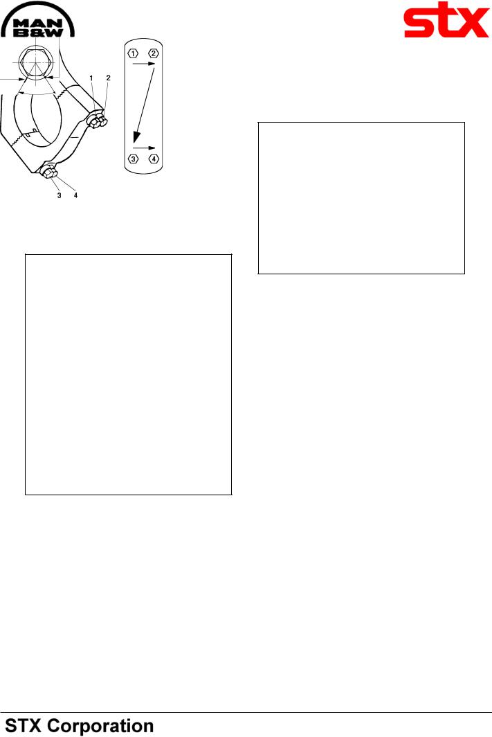
Tightening of Connecting Rod Screws
1st Step:
Tightening the screws in tightening order, illustrated in fig 1, using an initial torque of 250 Nm.
Fig 1.
2nd Step:
Once more, tightening the screws in prescribed tightening order, still using a torque of 250 Nm.
3rd Step:
Mark the four screws and the bearing cap felt-tippen, illustrated in fig 2.
Mark on screw collar
Mark on bearing cap
60°
Fig 2.
4th Step:
Check the screw tightening in prescribed order using a torque of 325 Nm.
Proper tightening condition is present, if the screws are not turned further during this test.
5th Step:
Check that the bearing can easily be moved on the journal.
Check of Connecting Rod Screws, Tightening
Condition:
Check of the tightening condition of connecting rod screws has to be executed within a short running period after remounting/mounting of the connecting rod.
This check can be fulfilled after only a few running hours at max. rpm at full load, but has to be fulfilled not later than 200 running hours after starting-up.
The tightening condition is checked with a torque af 325 Nm, executed in prescribed screw tightening order, see fig 1.
08028-0D/H5250/94.08.12
Tightening order by turning through a 60° ± 2° angle, i.e. until the marks on the screw collar and the connecting rod coincide radially.
Proper tightening condition is present, if the screws are not turned further during the test.
95.50 - ES0S
Working Card |
Tightening and Check of Connecting Rod Screws |
506-01.25 |
Page 3 (3) |
Edition 01H |
|
|
|
|
|
|
|
|
|
L23/30H |
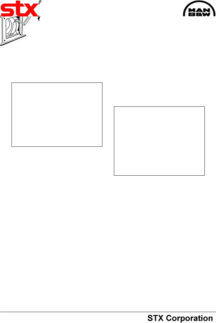
In order to ensure observation of any movement, the screws and the connecting rod should be applied with coinciding filt-pen marks prior to the test, see fig 3.
Mark on screw collar
Coinciding mark on bearing cap
Fig 3.
Any turning of the screws during the 325 Nm test indicates insufficient tightening condition, and in this case the big-end assembly has to be dismantled and investigated for evaluation and correction of failure.
As part of recommended overhaul and routine work, the tightening condition of connecting rod screws should also be checked, at certain running hours intervals, see page 500.24.
Nm
Fig 4.
08028-0D/H5250/94.08.12
95.50 - ES0S

Working Card |
In-situ Inspection of Connecting Rod Big-end Bearing |
506-01.30 |
Page 1 (3) |
Edition 01H |
|
|
|
|
|
|
|
|
|
L23/30H |
08028-0D/H5250/94.08.12
Safety precautions:
Stopped engine

 Shut-off starting air
Shut-off cooling water
Shut-off fuel oil
Shut-off cooling oil
Stopped lub. oil circul.
Description:
In-situ inspection and/or replacement of connecting rod big-end bearing, dismounting and mounting.
Starting position: |
|
Fuel injection valve dismounted, |
514-01.10 |
Crankcase open. |
|
Top cover for cylinder head removed.
Related procedure: |
|
Inspection of connecting rod |
|
big-end bearing |
506-01.16 |
Tightening and check of connecting |
|
rod screws |
506-01.25 |
Manpower: |
|
|
|
Working time |
: |
1 1/2 |
hours |
Capacity |
: |
1 |
man |
Data: |
|
|
|
Data for pressure and tolerance |
(Page 500.35) |
Data for torque moment |
(Page 500.40) |
Declaration of weight |
(Page 500.45) |
Special tools: |
|
|
Plate no |
Item no |
Note |
52006 |
070 |
|
52006 |
224 |
|
52006 |
273 |
80-360 Nm |
Tool combination for tightening of connecting rod screw, see working card 520-01.20.
Hand tools:
Open-end spanner 24 mm.
Replacement and wearing parts:
Plate no |
Item no |
Qty/ |
96.30 - ES0S
506-01.30 |
In-situ Inspection of Connecting Rod Big-end Bearing |
Working Card |
Edition 01H |
Page 2 (3) |
|
|
|
|
|
|
|
L23/30H |
|
|
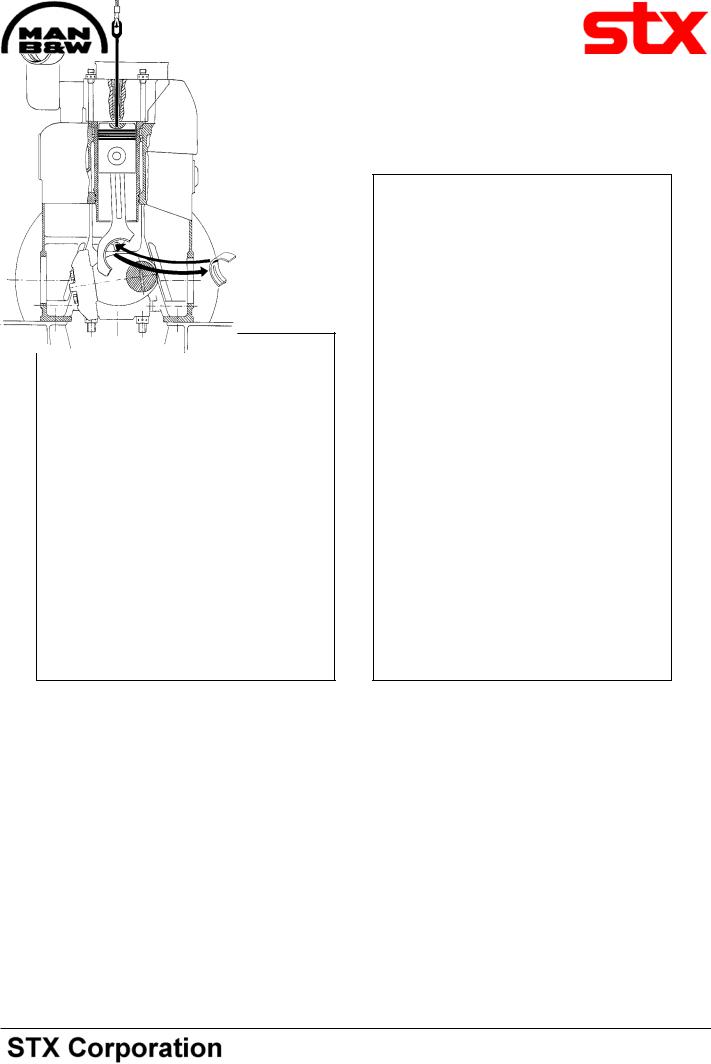
Turning the Piston in Correct Position
1)Turn the crankshaft into a position allowing the connecting rod to be losened.
2)Turn the crankshaft in a position allowing the connecting rod bearing cap to be dismounted, see fig 1.
a
a
Fig 1. |
Fig 2. |
Dismounting of Bearing Cap
3)Remove the fuel injector.
4)Insert the long-eye bolt and screw it into the thread hole in the piston, see fig 2.
5)Tighten it slightly by means of a tackle, see fig
2.
Removal of Bearing Shells
6) Dismount the bearing cap and bearing shell. For use of guide pin, see working card 506-01.00.
7) Lift the piston/connecting rod from the bearing journal.
Note: the piston/connecting rod should be lifted further then, just to allow dismounting of the upper bearing shell, see fig 2.
Inspection of Bearing Shells
8) Inspect the bearing shells, see working card
506-01.16.
08028-0D/H5250/94.08.12
96.30 - ES0S
Working Card |
In-situ Inspection of Connecting Rod Big-end Bearing |
506-01.30 |
Page 3 (3) |
Edition 01H |
|
|
|
|
|
|
|
|
|
L23/30H |
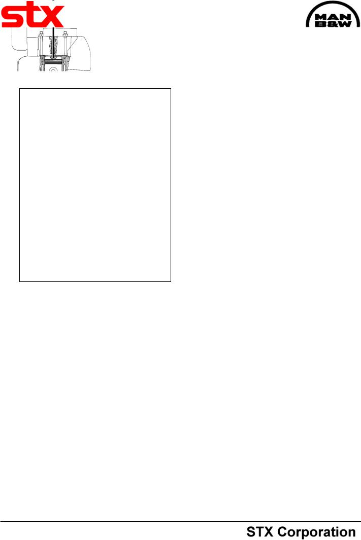
Fig 3.
Cleaning of Components before Mounting.
9) Clean all components, see working card 50601.20.
Mounting of Upper Bearing Shells
10) The bearing shell is placed in the bore, the contact surfaces of the shells to be in parallel to the contact surface of the connecting rod and the bearing cap respectively.
08028-0D/H5250/94.08.12
11)Ascertain that the crank throw concerned is in a position of approx 50 degrees before TDC.
12)Coat the journal with clean lubricating oil and lower the piston and connecting rod assembly slowly into correct landing on the journal.
While lowering the connecting rod, it must be guided by hand to ensure a correct approach and landing on the journal, see fig 4.
13) Lubricate the ends of the bearing shells (as in fig 2) with copaslip, molycote or simular.
Mounting of Bearing Cap
14)Mount the bearing cap with inserted lower bigend bearing shell, using the guide pin.
15)Lubricate threads and contact face of the connecting rod screws with copaslip or similar.
16)Mount the screws and tighten them slightly using an open-end spanner.
17)Slacken the tackle and dismount the eye screw from the piston crown.
Tightening of Connecting Rod Screws
18) Tighten the screws according to "Tightening Procedure for Connecting Rod Screw", see working card 506-01.25.
96.30 - ES0S