

- •500 Engine Data
- •500.00 Main Data for GenSets
- •500.01(01H) Introduction
- •500.02(01H) Safety
- •500.05(01H) Cross Section
- •500.10(01H) Key for Engine Designation
- •500.11(01H) Designation of Cylinders
- •500.12(01H) Engine Rotation Clockwise
- •500.20(01H) Code identification for Instruments
- •500.35(01H) Data for Pressure and Tolerance
- •500.35(11H) Data for Pressure and Tolerance
- •500.40(01S) Data for Torque Moment
- •500.45(01H) Declaration of Weight
- •500.50(01H) Ordering of Spare Parts
- •500.55(01H) Service Letters
- •500.60(01H) Conversion Table
- •500.65(01H) Basic Symbols for Piping
- •501 Operation of Engine
- •501.01(01H) Operating
- •501.05(01H) Out-of Service
- •501.10(01H) Starting-up after Out of Service Periods
- •501.15(02H) Guidelines for Longterm Low-Load Operation on HFO
- •501.25(01H) Operating a Diesel Engine at Low Frequency
- •502 Engine Performance and Condition
- •502.01(01H) Engine Performance and Condition
- •502.05(01H) Condensate Amount
- •502-01.00(01H) Engine Performance Data
- •503 Trouble Tracing
- •503.01(01H) Starting Failures
- •503.01(02H) Starting Failures
- •503.02(01H) Faults in Fuel Oil System
- •503.03(01H) Disturbances during Running
- •503.04(01H) Ignition in Crankcase
- •503.06(01H) Trouble Shooting Guide for Turbine Starter
- •503.09(01H) Trouble Shooting for Cooling Water System
- •503.10(01H) Trouble Shooting for Lubricating Oil Cooler
- •504.01(01H) Lubricating Oil Specification
- •504.01(05H) Lubricating Oil Specification
- •504.03(01H) Maintenance of Lubricating Oil Condition
- •504.05(01H) Lubricating Points
- •504.06(01H) Lubricating Oil in Base Frame
- •504.06(04H) Lubricating Oil in Base Frame
- •504.20(02H) Fuel Oil Specification
- •504.20(04H) Fuel Oil Specification
- •504.25(01H) Fuel Oil Quality
- •504.26(01H) Nomogram for Determination of CCAI
- •504.26(02H) Nomogram for Determination of CCAI
- •504.27(01H) Analysis Data
- •504.30(01H) Fuel Oil Cleaning
- •504.40(01H) Fresh Water System Treatment
- •504.40(02H) Freshwater System Treatment
- •505 Cylinder Head
- •505.01(01H) Cylinder Head
- •505-01.00(01H) Dismantling of Cylinder Head
- •505-01.05(01H) Inspection of Inlet Valve, Exhaust Valve and Valve Guide
- •505-01.15(01H) Valve Rotator
- •505-01.20(01H) Replacement of Valve Guide
- •505-01.26(01H) Indicator Valve
- •505-01.30(01H) Replacement of Sleeve for Fuel Injector
- •505-01.35(01H) Replacement of Valve Seat Ring
- •505-01.40(01H) Mounting of Cylinder Head
- •505-01.45(01H) Inspection of Cylinder Head Cooling Water Space
- •50501-01H Cylinder Head
- •50502-01H Valve Spindles and Valve Gear
- •50508-01H Indicator Valve
- •50510-01H Cylinder Head, Top Cover
- •506 Piston, Connecting Rod and Cylinder Liner
- •506.01(01H) Piston, Connecting Rod and Cylinder liner
- •506-01.05(01H) Separation of Piston and Connecting Rod
- •506-01.10(01H) Piston
- •506-01.15(01H) Connecting Rod
- •506-01.25(01H) Tightening and Check of Connecting Rod Screws
- •506-01.30(01H) In-situ Inspection of Connecting Rod Big-end Bearing
- •506-01.35(01H) Inspection and Honing of Cylinder Liner
- •506-01.40(01H) Replacement of Cylinder Liner
- •50601-01H Piston and Connecting Rod
- •507 Camshaft and Camshaft Drive
- •507.01(01H) Camshaft and Camshaft Drive
- •507-01.00(01H) Check of Camshaft and Camshaft Drive
- •507-01.05(01H) Inspection and Replacement of Camshaft Bearing
- •507-01.20(01H) Adjustment of Camshaft
- •50701-01H Intermediate Wheel
- •50705-01H Camshaft and Camshaft Bearing
- •50705-07H Camshaft and Camshaft Bearing
- •508-01.00(01S) Inspection of Valve Roller Guides
- •50801-01H Roller Guide and Push Rods
- •509.01(01H) Control and Safety Systems
- •509.05(01H) Instruments and Automatics
- •509.10(02H) Lambda Controller
- •509.35(01H) Starting Box
- •509-01.05(01H) Functional Test and Adjustment of Overspeed Trip
- •509-05.00(01S) Adjustment and Test of ON/OFF Pressostate
- •509-05.01(01S) Adjustment and Test of ON/OFF Thermostate
- •50903-01H Overspeed Device
- •50905-03H Prelubricating Oil Alarm (LAL 25)
- •50905-04H Instrument Panel
- •50907-02H Thermometer
- •50908-01H Pick-up
- •50910-01H Lambda Controller
- •50935-01H Starting Box
- •510 Crankshaft and Main Bearings
- •510.01(01H) Crankshaft and Main Bearings
- •510-01.00(05H) Checking of Main Bearings Alignment (Autolog)
- •510-01.05(01H) Inspection of Main Bearing Shells
- •510-01.10(01H) Inspection of Guide Bearing Shells
- •51001-01H Crankshaft
- •51002-02H Resilient Gear Wheel
- •51003-02H Flywheel with Gear Rim
- •511S Engine Frame and Base Frame
- •511.01(01H) Engine Frame and Base Frame
- •511-01.00(01H) Functional Test of Crankcase Safety Relief Valves
- •51101-02H Frame with Main Bearings
- •51102-02H Mounting of Pumps
- •51106-02H Covers on Frame
- •51106-03S Covers on Frame
- •512 Turbocharger System
- •512.01(01H) Turbocharger System
- •512-01.00(01H) Overhaul of Charging Air Cooler
- •512-15.00(01H) Water Washing of Turbine Side
- •51202-01S Exhaust Pipe Arrangement
- •51203-03H Turbocharging Arrangement
- •513 Compressed Air System
- •513.01(01S) Compressed Air System
- •513.01.30(01H) Overhaul, Test and Inspection of Turbine Starter
- •513-01.40(01H) Main Starting Valve
- •513-01.90(01H) Check of Compressed Air Piping System
- •51309-01H Turbine Starter
- •51310-01H Main Starting Valve
- •51314-01S Starting Valve
- •51315-03H Main Stop Valve
- •51316-03H Air Strainer
- •51319-02H Safety Valve
- •51320-01H ON-OFF Valve for Jet System
- •51321-01H Air Filter
- •514 Fuel Oil System
- •514.01(01H) Internal Fuel Oil System
- •514-01.05(01H) Fuel Injection Pump and Fuel Injection Pipe
- •514-01.10(02H) Fuel Injection Valve
- •514-01.15(01H) Fuel Oil Split Filter
- •514-01.90(01H) Check of Fuel Oil Piping System
- •514-05.01(01H) Adjustment of The Maximum Combustion Pressure
- •51401-01H Fuel Injection Pump
- •51402-01H Fuel Injection Valve
- •51403-01H Fuel Oil Filter Duplex
- •51404-01H Fuel Injection Pipe
- •51430-01H Pipes on Cylinder Section
- •515 Lubricating Oil System
- •515.01(01H) Internal Lubricating Oil System
- •515.06(01H) Lubricating Oil Cooler
- •515-01.00(01H) Lubricating Oil Pump, Engine Driven
- •515-01.10(01H) Lubricating Oil Filter
- •515-01.20(01H) Lubricating Oil, Thermostatic Valve
- •515-01.90(01H) Check of Lubricating Oil Piping System
- •515-06.00(02H) Lubricating Oil Cooler
- •51501-03H Lubricating Oil Pump (Gear Driven)
- •51502-01H Lubricating Oil Filter (Type A)
- •51502-02H Lubricating Oil Filter (Suppl. for Plate 51502-01H)
- •51504-01H Prelubricating Pump
- •51506-01H Lubricating Oil Cooler
- •51525-01H Hand Wing Pump
- •51530-01H Lubricating Oil Separator
- •516 Cooling Water System
- •516.01(01H) Cooling Water System
- •516.04(01H) Cooling Water Thermostatic Valve
- •516-01.90(01H) Check of Cooling Water System
- •516.04-00(01H) Cooling Water, Thermostatic Valve
- •51604-01H Cooling Water Thermostatic Valve
- •51610-01H High Temperature Fresh Water Pump
- •51625-01H Pipes on Cylinder Head
- •51635-01H Preheater - Fresh Water
- •517 Special Equipment
- •518 Driven Machinery
- •519 Specific Plant Information
- •519.03(01S) Resilient Mounting of Generating Sets
- •519-03.00(01S) Fitting Instructions for Resilient Mounting of GenSets
- •519-03.00(02S) Fitting Instructions for Resilient Mounting of GenSets
- •519-03.00(03S) Fitting Instructions for Resilient Mounting of GenSets
- •519-03.05(01S) Replacement of Conicals
- •519-03.10(01S) Replacement of Conicals
- •520 Tools
- •520.01(01H) Introduction to Spare Part Plates for Tools
- •520-01.05(01H) Application of Hydraulic Tools
- •520-01.10(01H) Maintenance of Hydraulic Tools
- •520-01.15(01H) Tightening with Torque Spanner

Working Card |
Connecting Rod |
506-01.15 |
Page 1 (4) |
Edition 01H |
|
|
|
|
|
|
|
08028-0D/H5250/94.08.12
L23/30H
Safety precautions: |
Special tools: |
|
|
Stopped engine |
Plate no |
Item no |
Note |
Shut-off starting air |
|
|
|
Shut-off cooling water |
52006 |
273 |
80-360 Nm |
Shut-off fuel oil |
52006 |
618 |
225-250 Nm |
Shut-off cooling oil |
|
|
|
Stopped lub. oil circul. |
|
|
|
Description:
Cleaning, inspection and test measurement of connecting rod.
|
Hand tools: |
Starting position: |
Inside micrometer (195 mm). |
|
Feeler gauge 0.15 - 0.20 mm. |
Connecting rod has been |
|
dismantled from piston |
506-01.05 |
Related procedure: |
|
Mounting of piston and |
|
connecting rod |
506-01.20 |
Manpower: |
|
|
|
Replacement and wearing parts: |
||
Working time |
: |
1/2 |
hour |
Plate no |
Item no |
Qty / |
Capacity |
: |
1 |
man |
|
|
|
Data: |
|
|
|
|
|
|
Data for pressure and tolerance |
(Page 500.35) |
|
|
|||
Data for torque moment |
|
(Page 500.40) |
|
|
||
Declaration of weight |
|
|
(Page 500.45) |
|
|
|
95.50 - ES0S
506-01.15 |
Connecting Rod |
Working Card |
Edition 01H |
Page 2 (4) |
|
|
|
|
|
|
|
L23/30H
Cleaning of Connecting Rod
1.Clean all machined surfaces on the connecting
rod.
2.Degrease the serrated joint faces, tapped holes and connecting rod screws with a volatile solvent and blow dry with working air.
Visual Inspection of Serrated Faces
3.Inspect the serrated joint faces.
Damages, in the form of visible wear marks and pittings or even cracks, may be in the serration due to relative movements between the surfaces.
Wear marks and cracks are visible, but not perceptible with a fingernail. Pittings and impact marks are both visible and perceptible.
Note!! Handle the connecting rod with care. In case of damaged serration caused by improper handling, the bearingcapcannolongerbetightenedtotheconnecting rod without ovalness of the big-end bore.
4.Register observed damages in the scheme
"Connecting Rod Inspection" for historic use only. See page 4.
5.Carefully smooth single raised spots in the serration caused by pitting and impact marks with a filesmall.
Inspection of Connecting Rod Screws
6.Inspect the connecting rod screws for seizures in the threads and pittings on the contact surfaces of the screwheads.
7.Turn the connecting rod screws into bottom position in the threaded screw holes by hand.
If screws |
Then |
|
|
have seizures in |
Renew the screws |
threads or pittings on |
|
contact surface |
|
cannot be turned into |
Renew the screws |
bottom position by hand |
|
|
|
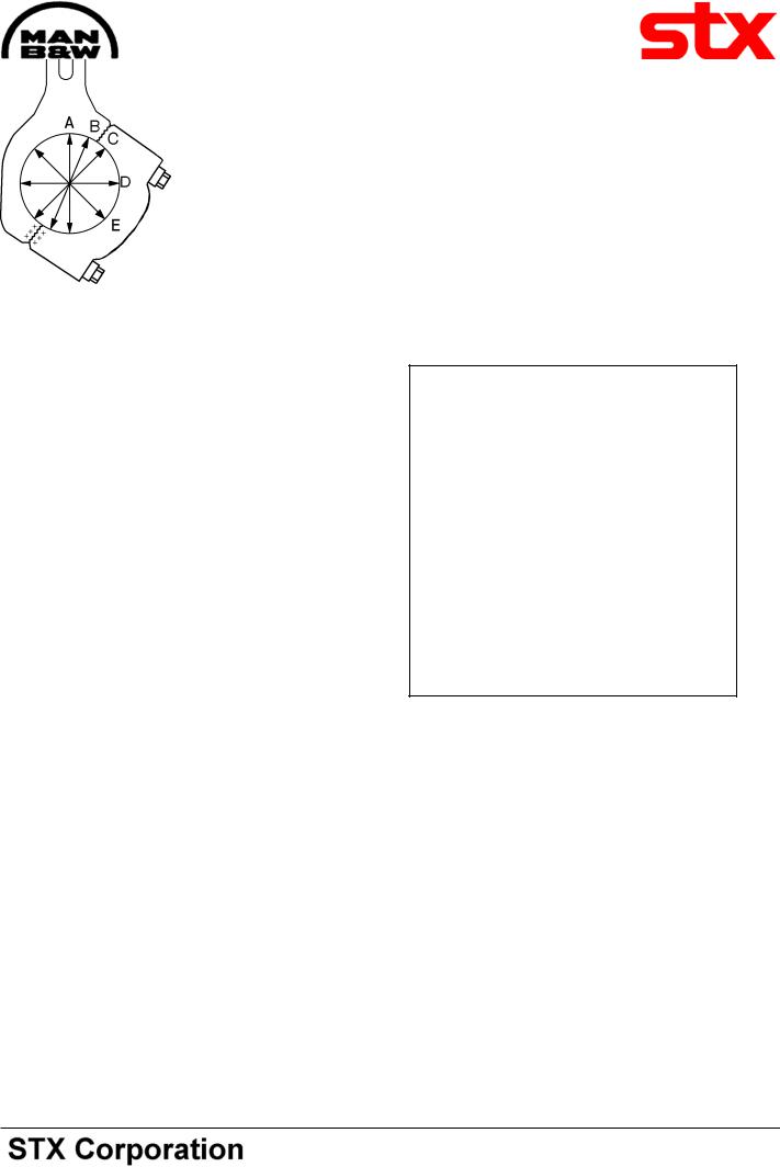
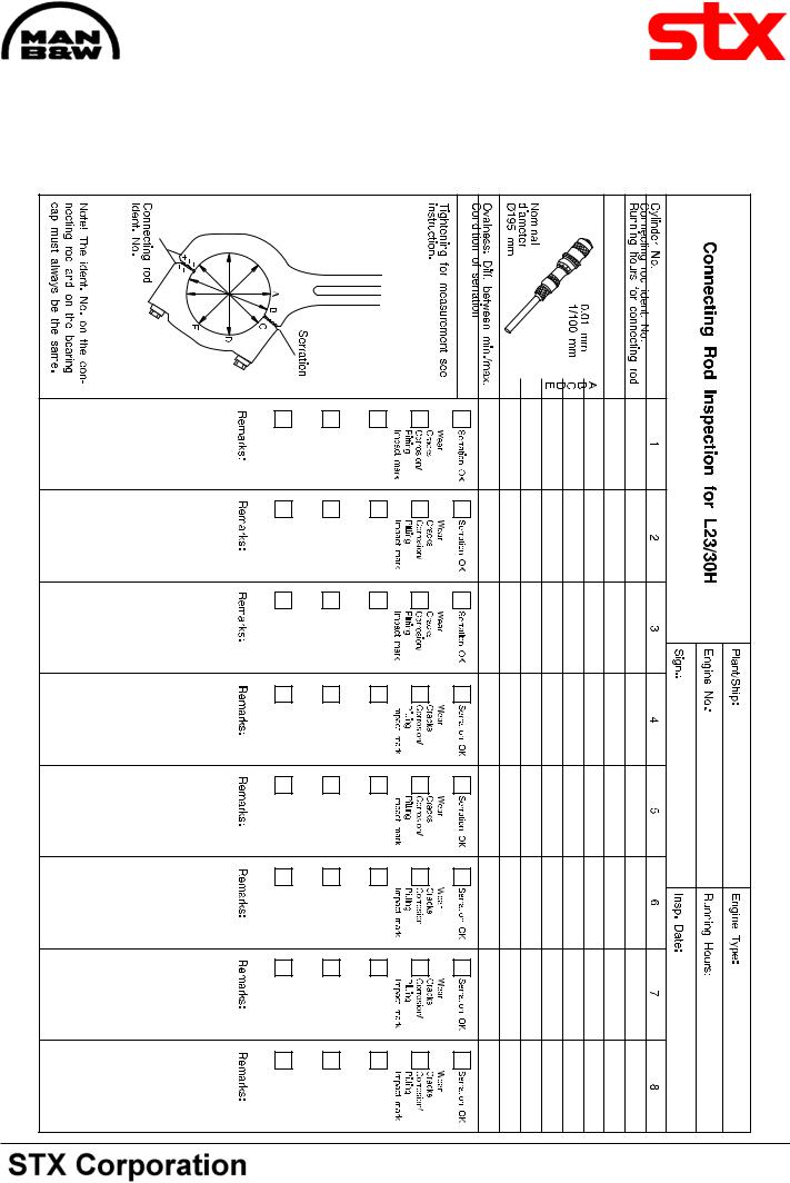
Measurement of Big-end Bore
For check of ovalness the bearing cap has to be mounted onto the big-end bore without bearing shells.
Note !! The ident. No on the connecting rod and the bearing cap must always be the same, see fig 3.
8.Mount the bearing cap onto the connecting rod
Fig. 1. Point of measurement
by means of the connecting rod screws.
9.Tighten the screws with the prescribed torque, see working card 506-01.25.
10.Measure five different diameters in the middle of the boring, see fig 1.
11.Register the measurements in the scheme "Connecting Rod Inspection". See page 4.
12.Calculate the maximum ovalness as the difference between biggest and smallest diameter measured.
13.Check if maximum ovalness is exceeded, see page 500.35.
If |
Then |
08028-0D/H5250/94.08.12
95.50 - ES0S
Working Card |
Connecting Rod |
506-01.15 |
Page 3 (4) |
Edition 01H |
|
|
|
|
|
|
|
08028-0D/H5250/94.08.12
maximum ovalness is |
Renew the complete |
|||
exceeded |
|
connecting rod, screws |
||
|
|
and bearing shells. |
||
maximum ovalness is |
Reuse the connecting rod |
|||
not exceeded |
|
|
|
|
Example of Measurement Results |
|
|||
Connecting Rod Inspection for L23/30H |
|
|||
Cylinder no. |
|
1 |
2 |
|
Connecting |
rod ident no. |
|
|
|
Running hours for connecting rod |
|
|
|
|
|
A |
- 0,5 |
- 3,0 |
|
|
0,01 mm |
- 2,0 |
- 7,0 |
|
|
1/100 mm B |
|
||
Nominal |
C |
- 1,5 |
- 5,0 |
|
D |
+ 5,0 |
+ 5,5 |
|
|
diameter |
|
|||
Ø195 mm |
E |
+ 3,0 |
+ 3,5 |
|
Ovalness: Diff. between min./max. |
7,0 |
12,5 |
|
|
Condition of |
serration |
Serration OK |
Serration OK |
Serration OK |
Tightening for measurement see |
|
|
|
|
instruction. |
|
|
|
|
|
|
Wear |
Wear |
Wear |
|
|
Cracks |
Cracks |
Cracks |
|
|
Corrosion/ |
Corrosion/ |
Corrosion/ |
|
|
Pitting |
Pitting |
Pitting |
|
Serration |
|
|
|
|
|
Impact mark |
Impact mark |
Impact mark |
|
|
A |
B |
|
|
|
|
|
|
C |
|
|
|
|
|
|
|
Remarks: |
Remarks: |
Remarks: |
|
|
|
|
D |
tobe |
|
|
|
|
|
tobe |
|
|
++ |
+ |
E |
reused |
rejected |
|
|
+ |
|
+ |
|
|
|
|
|
+ |
|
|
|
|
|
Connecting rod
Ident no.
Note ! The ident no. on the connecting rod and on the bearing cap, must always be the same.
Fig 2. "Connecting Rod Inspection".
The example, see fig 2, shows measurements and damage observations for two connecting rods on the scheme "Connecting Rod Inspection" (in case the specified maximum ovalness is exceeded, contact MAN B&W Diesel A/S, Holeby for overhaul).
For connecting rod No 1 the maximum ovalness is 0.07 mm and thus reuse is acceptable.
L23/30H
0.125mmandthereforetheconnectingrodisrejected.
Inspection of Connecting Rod Bush
1.Inspect the surface of the piston pin and the connecting rod bush.
2.Measure the clearance between the piston pin and bush.
3.Check if max clearance is exceeded, see page 500.35.
If the specified clearance is exceeded, contact MAN B&W Diesel A/S, Holeby for replacement.
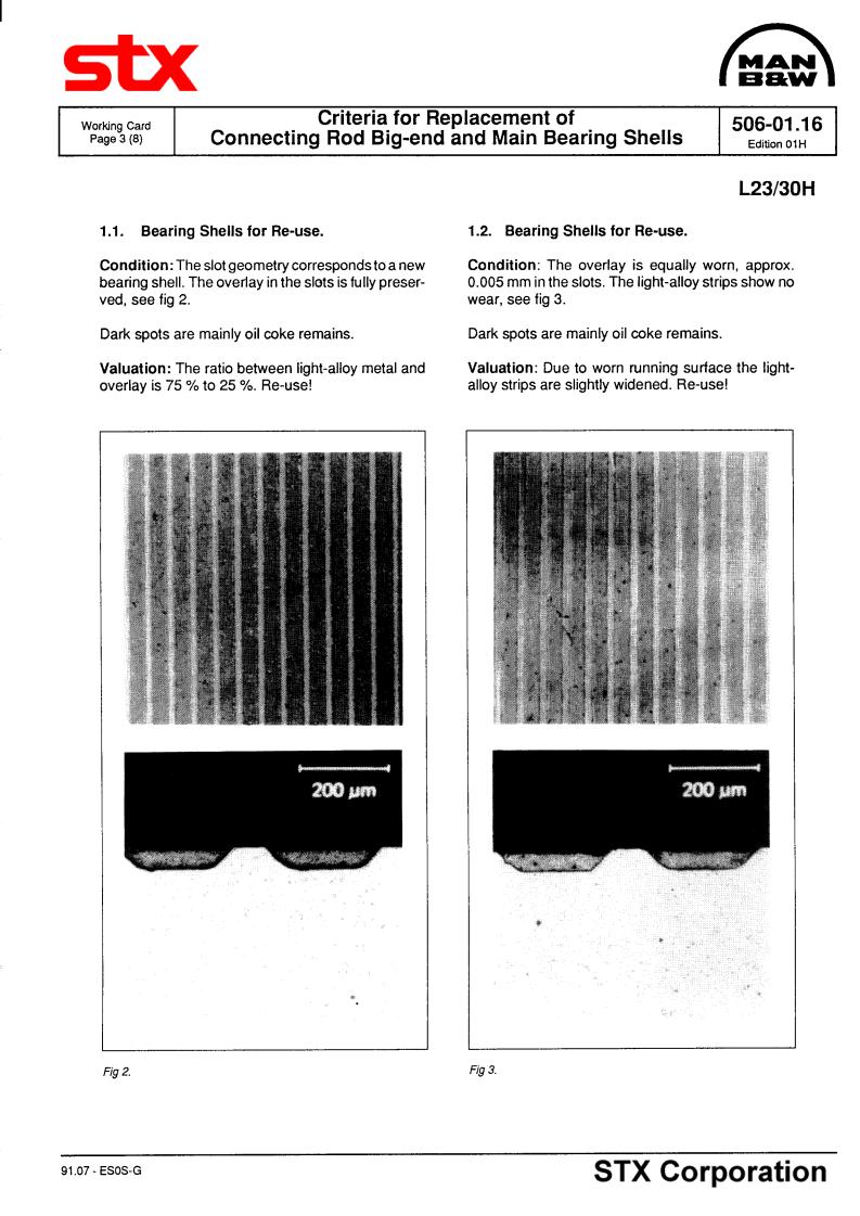
Inspection of Bearing Shells for Big-end
Criteria for replacement of connecting rod big-end bearing, see working card 506-01.16.
Connecting rod
Ident No
Fig 3.
For connecting rod No 2 the maximum ovalness is
95.50 - ES0S
506-01.15 |
Connecting Rod |
Working Card |
|
Edition 01H |
Page 4 (4) |
||
|
|||
|
|
|
L23/30H |
08028-0D/H5250/94.08.12 |
95.50 - ES0S |


Working Card |
Mounting of Piston and Connecting Rod |
506-01.20 |
Page 1 (4) |
Edition 01H |
|
|
|
|
|
|
|
|
|
L23/30H |
08028-0D/H5250/94.08.12
Safety precautions: |
Special tools: |
|
|
||
|
|
Stopped engine |
Plate no |
Item no |
Note |
|
|||||
|
|
Shut-off starting air |
|
|
|
|
|
|
|
|
|
|
|
Shut-off cooling water |
52006 |
021 |
|
|
|
||||
|
|
Shut-off fuel oil |
52006 |
033 |
|
|
|
||||
|
|
Shut-off cooling oil |
52006 |
116 |
|
|
|
||||
|
|
Stopped lub. oil circul. |
52006 |
141 |
|
|
|
||||
|
|
|
52006 |
224 |
|
Description: |
|
|
|
||
Mounting of piston and connecting rod assembly, |
|
|
|
||
after overhaul and/or inspection. |
|
|
|
||
Starting position: |
|
Hand tools: |
Piston mounted on the connecting rod, crank- |
Open-end spanner 24 mm. |
|
shaft turned in the right position and the cylinder |
Clean lubricating oil. |
|
liner is OK, see working card 506-01.35. |
|
|
Related procedure: |
|
|
Tightening of connecting rod screws |
506-01.25 |
|
Mounting of cylinder head |
505-01.40 |
|
Manpower: |
|
|
|
|
Replacement and wearing parts: |
||
Working time |
: |
1 1/2 |
hours |
|
Plate no |
Item no |
Qty/ |
Capacity |
: |
2 |
men |
|
|
|
|
|
|
|
|
|
50601 |
093 |
1/cyl |
Data: |
|
|
|
|
50601 |
103 |
1/cyl |
|
|
|
|
|
50601 |
115 |
1/cyl |
Data for pressure and tolerance |
(Page 500.35) |
50601 |
127 |
1/cyl |
|||
Data for torque moment |
|
(Page 500.40) |
|
|
|
||
Declaration of weight |
|
(Page 500.45) |
|
|
|
||
95.50 - ES0S
506-01.20 |
Mounting of Piston and Connecting Rod |
Working Card |
Edition 01H |
Page 2 (4) |
|
|
|
|
|
|
|
L23/30H
Mounting of Tools
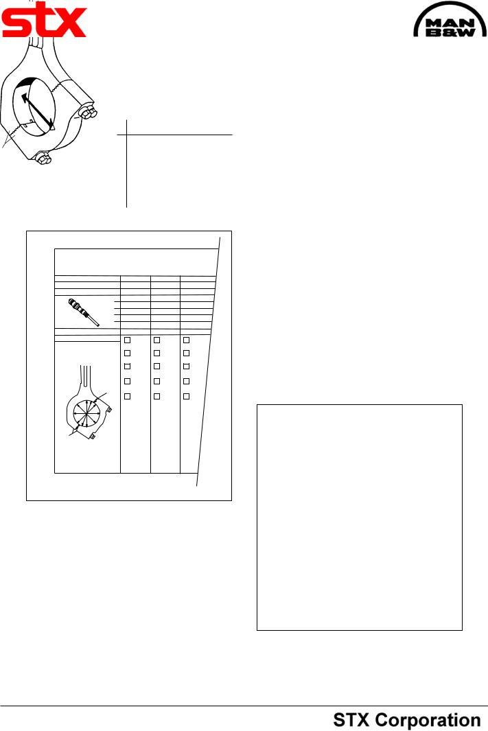
1)Mount the lifting device comprising eye screw, shackle and wire rope on the piston.
2)Lift up the piston and connecting rod and mount the piston and scraper rings, see point 14, and working card 506-01.10.
3)Remove the backstop for cylinder liner and place the piston guide ring on top of the cylinder liner, see fig 1.
Note: A crank throw position of approx 50 degrees before TDC will ensure this and also be suitable for the further mounting procedure.
Mounting of Big-end Bearing
6) Lower the piston further down, lubricate the ends of the bearing shells (as in fig. 2) with copaslip, molycote pasta or similar and mount the upper shell of the big-end bearing.
Fig 1.
Lowering of Piston and Connecting Rod
4)When the piston approaches the guide ring, stop the lowering, coat guide ring, piston, piston rings and scraper ring, with clean lubricating oil in order to minimize friction during the subsequent lowering of the assembly.
5)Make sure that the crank throw is in a position allowing the connecting rod to go clear of both crank journal and cylinder liner skirt during further lowering.
Fig 2.
7)Coat the crank journal with clean lubricating oil.
8)Lower the piston and connecting rod slowly into correct landing on the journal.
During this the connecting rod must be guided by hand to ensure correct approach and landing on the journal, see fig 3.
08028-0D/H5250/94.08.12
95.50 - ES0S
Working Card |
Mounting of Piston and Connecting Rod |
506-01.20 |
|||
Page 3 (4) |
Edition 01H |
||||
|
|
|
|
|
|
|
|
|
|
|
|
|
|
|
|
|
L23/30H |
|
|
|
Note: The ident. No. on the connecting rod and on the |
||
|
|
|
|||
|
|
|
bearing cap must always be the same, see fig 4. |
||
|
|
|
10) |
Lubricate threads and contact face of the |
|
|
|
|
connecting rod screws with copaslip, molycote pasta |
||
|
|
|
or similar. |
|
|
|
|
|
11) |
Mount the screws and tighten them slightly |
|
|
|
|
using an open end spanner. |
|
|
|
|
|
12) |
Slacken the tackle and dismount the eye screw/ |
|
|
|
|
shackle from the piston. |
|
|
|
|
|
|
|
|
08028-0D/H5250/94.08.12
Fig 3.
Mounting of Bearing Cap
9) Mount the bearing cap with inserted lower shell of the big-end bearing, using the guide pin, see fig 4.
Con. Rod - Ident No.
Fig 4.
Fig 5.
Tightening of Connecting Rod Screws
13) Tighten the screws according to "Tightening Procedure for Connecting Rod Screws", see working card 506-01.25.
Fitting of Piston and Scraper Rings
14) Piston rings should only be removed from and fitted to the piston by the use of a special tool, the socalled piston ring opener.
95.50 - ES0S
506-01.20 |
Mounting of Piston and Connecting Rod |
Working Card |
Edition 01H |
Page 4 (4) |
|
|
|
|
|
|
|
L23/30H |
|
|
If the rings are opened further than necessary there is a risk of overstressing, which means that rings will become permanently distorted and will not confirm to the inner running surface of the cylinder.
The piston rings should be installed with the identification mark, which is stamped into the ring close to the ring joints, facing upwords, see working card 50601.10 "Piston".
Joint pin for |
Joint coil spring to be |
|
coil spring |
||
placed opposite to ring joint |
||
|
Ring joint
Fig 6.
Before fitting the coil spring loaded scraper ring, the coil spring is dismantled from the ring by removal of the joint pin. The coil spring is placed and assembled in the ring groove. Then the scraper ring is fitted in the groove in such a way that the ring joint is approximately 180° offset to the spring joint.
Ascertain correct assembling by checking the back clearance.The back clearance is sufficient when the face of the ring is below the groove edge when the ring is pressed against the bottom of the groove.
When installed on the piston the rings should be pushed back and forth in the grooves to make sure that they can move freely. It is also advisable to insert a feeler gauge of adequate thickness between ring and groove.
Adequate clearance is present so the feeler gauge can be moved all the way round.
To prevent gas leakage through coinciding ring joints the piston rings should be turned into positions offsetting the ring joint 180° to each other.
08028-0D/H5250/94.08.12
95.50 - ES0S