


Index |
Cylinder Head |
505 |
|
Page 1 (1) |
|||
|
|
||
|
|
|
|
L23/30H |
Description |
|
Cylinder Head .................................................................................................................. |
505.01 (01H) |
Working Card |
|
Dismantling of Cylinder Head ..................................................................................... |
505-01.00 (01H) |
Inspection of Inlet Valve, Exhaust Valve and Valve Guide......................................... |
505-01.05 (01H) |
Reconditioning of Valve Spindle Seat and Valve Seat Ring ....................................... |
505-01.10 (01H) |
Valve Rotator ............................................................................................................. |
505-01.15 (01H) |
Replacement of Valve Guide ..................................................................................... |
505-01.20 (01H) |
Indicator Valve ........................................................................................................... |
505-01.26 (01H) |
Replacement of Sleeve for Fuel Injector .................................................................... |
505-01.30 (01H) |
Replacement of Valve Seat Ring ............................................................................... |
505-01.35 (01H) |
Mounting of Cylinder Head ......................................................................................... |
505-01.40 (01H) |
Inspection of Cylinder Head Cooling Water Space .................................................... |
505-01.45 (01H) |
Plates |
|
Cylinder Head ..................................................................................................................... |
50501-01H |
Valve Spindles and Valve Gear........................................................................................... |
50502-01H |
Indicator Valve .................................................................................................................... |
50508-01H |
Cylinder Head, Top Cover ................................................................................................... |
50510-01H |
08028-0D/H5250/94.08.12
96.03 - ES0U

Description |
Cylinder Head |
505.01 |
Page 1 (1) |
Edition 01H |
|
|
|
|
|
|
|
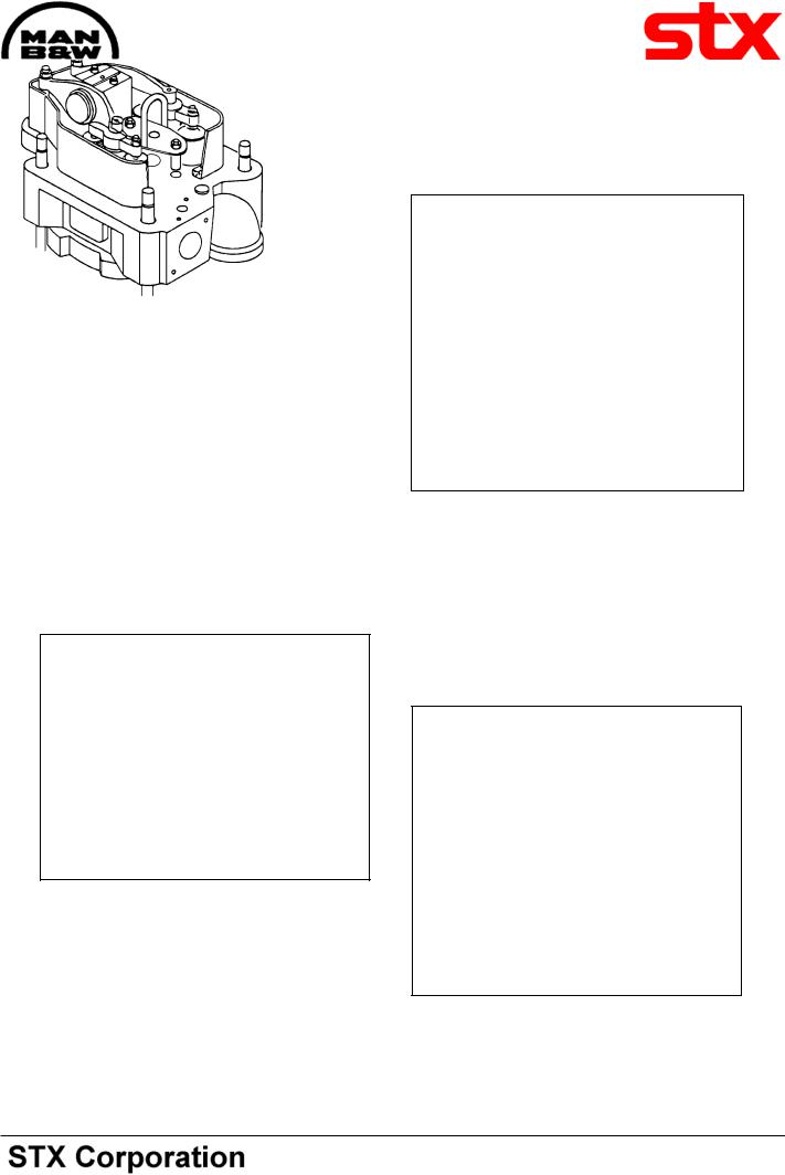
Cylinder Head
The individual cast-iron cylinder heads, one for each cylinder unit, are equipped with a centrally situated fuel injection valve, two inlet valves, two exhaust valves and one indicator cock.
The head has a thick, bore-cooled flame plate for satisfactory control of mechanical and thermal loads and stress.
The cylinder head is attached by means of 4 nuts and 4 studs screwed into deep bosses in the engine frame top plate. The nuts are tightened by means of hydraulic tools.
L23/30H
Inlet and Exhaust Valves
The inlet and exhaust valve spindles are identical and therefore interchangeable.
Thevalvespindlesaremadeofheat-resistantmaterial. Hard metal is welded on to the valve spindle seats.
The valve spindles are fitted with valve rotators which turn the spindles a little each time the valves open.
The cylinder head is equipped with replaceable seat rings for inlet and exhaust valves.
Theseatingsurfacesarehardenedinordertominimize wear and prevent dent marks, on the inlet seat by induction hardening, on the exhaust seat by hard metal armouring.
08028-0D/H5250/94.08.12
95.50 - ES0U-G

Working Card |
Dismantling of Cylinder Head |
505-01.00 |
Page 1 (2) |
Edition 01H |
|
|
|
|
|
|
|
|
|
L23/30H |
08028-0D/H5250/94.08.12
Safety precautions:
Stopped engine

 Shut-off starting air
Shut-off cooling water
Shut-off fuel oil
Shut-off cooling oil
Stopped lub. oil circul.
Description:
Dismantling of cylinder head for inspection and/or overhaul.
Starting position:
Cooling water has been drained from engine.
Related procedure:
Dismounting of piston and connecting
rod |
|
|
|
506-01.00 |
Dismounting and inspection of inlet valve, |
||||
exhaust valve and valve guide |
505-01.05 |
|||
Dismantling, overhaul and test |
|
|||
pressure of fuel oil valve |
|
514-01.10 |
||
Manpower: |
|
|
|
|
Working time |
: |
1 |
hour |
|
Capacity |
: |
2 |
men |
|
Data: |
|
|
|
|
Data for pressure and tolerance |
(Page 500.35) |
|||
Data for torque moment |
|
(Page 500.40) |
||
Declaration of weight |
|
|
(Page 500.45) |
|
Special tools: |
|
|
Plate no |
Item no |
Note |
52021 |
011 |
Oil injector, |
52021 |
011 |
(Complete) |
52021 |
501 |
4 pieces |
52021 |
513 |
1 piece |
52021 |
155 |
|
52005 |
014 |
|
52021 |
251 |
Hydraulic tools |
Hand tools:
Ring and open-end spanner, 17 mm. Ring and open-end spanner, 19 mm. Ring and open-end spanner, 27 mm. Allen key, 8 mm.
Replacement and wearing parts:
Plate no |
Item no |
Qty/ |
95.50 - ES0S
505-01.00 |
Dismantling of Cylinder Head |
Working Card |
|
Edition 01H |
Page 2 (2) |
||
|
|||
|
|
|
|
L23/30H |
|
|
Draining of cooling water, disconnection of pipes etc.
1)Open the drain cock and vent cock for cooling water.
2)Take off the top cover.
3)Take off the front cover which gives access to the injection pump.
4)Disconnect the fuel oil high-pressure pipe.
5)Disconnect the rocker arm lubricating oil pipe.
6)Remove the thermometer attachment branch (cooling water outlet pipe).
7)Remove the exhaust pipe flange screws.
8)Remove the cylinder head nuts, see Fig 1, by means of hydraulic jacks. See working card 52001.05.
Fig 1
Mounting of Lifting Tool while the Fuel Injection Valve is Placed in the Cylinder Head.
9)Disconnect the two nuts which is holding down the fuel injection valve.
10)Remove the two distance pieces.
11)Mount the lifting tool by means of the two nuts. See Fig 2.
Fig 2
Mounting of Lifting Tool with the Fuel Injection Valve is Removed from the Cylinder Head.
12)Mount the two-distance pieces to the studs.
13)Mount the lifting tool by means of the two nuts. See Fig 3.
Fig 3
14)Attach the hook to the lifting tool and lift the cylinder head away.
08028-0D/H5250/94.08.12
95.50 - ES0S