Скачиваний:
225
Добавлен:
14.07.2019
Размер:
7.68 Mб
Скачать

520-01.25

Max. Pressure Indicator

Working Card

Edition 01H

Page 2 (2)


L23/30H

V28/32S

Operation

1)Open the indicator valve and blow through shortly.

2)Connect the max pressure indicator to the indicator valve and open the valve.

3)After 3-5 seconds read the max. pressure on the gauge.

Attention: The indicator valve has to be open while reading the max. pressure on the gauge. The measuring period should not exceed 30 seconds.

4)Close the indicator valve and open the valve screw (5), fig 1.

5)Disconnect the max. pressure indicator and close the valve screw (5), fig 1.

6)Measure the remaining cylinders by following step 1 to 5.

Overhaul Intervals

1)Dismount and clean the non-return valve after 200 measuring periods. If the pressure drop is more than 5 bar within 60 seconds (test pressure 100 bar) it is recommended to relap the non-return valve.

2)Check the pressure gauge after 1,000 measuring periods or after 12 months use.

Attention: Use only exhaust gas or nitrogen gas and never oil for testing the pressure drop and the pressure gauge. By using oil carbon will deposit inside the measuring instrument.

Dismantling and Assembly

1)Dismount the valve screw (5), fig 1.

2)Turn the screw (4) into the instrument to enable dismounting of the housing (1).

3)Loosen the screws (2) (4 pieces) for separating upper and lower part.

1

2

5


4


3


1

Housing

2

Allen screw

3

Sealing

4

Screw

5

Valve screw


Fig 1 Pressure Indicator.

4)After separation of the upper and lower part, take off the non-return valve assembly.

5)Lap the valve and the valve seat.

6)Renew the sealing ring (3) and screws (2), if necessary.

7)When mounting the upper and lower part, use only original screws.

8)Coat the screws (2) with copaslip or similar and tighten to 10 Nm.

9)After assembly the instrument can be used without any new calibration.

Check of the Pressure Gauge

10)Testing of the instrument should only be made by skilled specialists, and it is recommended to send the instrument to MAN B&W Diesel A/S, Holeby for calibration.

08028-0D/H5250/94.08.12

96.03 - ES0

08028-0D/H5250/94.08.12

Page 1 (4)

Tools for Cylinder Head

52005-04H

Plate


L23/30H


Illustration of Tools


Designation

Dimensions

S/E

Item


A

B

C


No


Lifting tool for cylinder head,


complete.

139

113

68

S 014


Mounting tool for valves,


complete.

248 65 ø72 S 051

Max. pressure indicator.

S 109

Spare Parts:


Valve screw

110

Non-return valve, complete incl.


seals and housing screws.

122

Connecting nut incl. wedge for


mounting

134

Pressure gauge 0-180 bar.

146

S = Standard E = Extra

01.17 - ES0

52005-04H

Tools for Cylinder Head


L23/30H

Plate

Page 2 (4)


Illustration of Tools

Designation


Extractor for valve seat ring


(complete).


Grinding table for cylinder head, with bracket for wall mounting, complete.

Grinding table for cylinder head, with frame for floor mounting, complete.

Dimensions

S/E

Item

A

B C

No


ø137

290

E 504

846 426 648 E 254

833 1050 744 E 301

08028-0D/H5250/94.08.12

S = Standard E = Extra

01.17 - ES0

Plate

Page 3 (4)

Tools for Cylinder Head

52005-04H


L23/30H

Illustration of Tools

08028-0D/H5250/94.08.12

Designation

Dimensions

A

B

C


Grinding machine for valve seat


ring, complete.


Spare Parts:


Stone


Guide


Grinding machine for valve spindle, complete.

Spare Parts:

Stone

Mounting tool for valve seat rings,


complete.

ø78 315

S/E

Item

No


E350

362

374

E408

421

E 457

S = Standard E = Extra

01.16 - ES0

52005-04H

Tools for Cylinder Head


L23/30H

Plate

Page 4 (4)

Illustration of Tools

Designation

Grinding tool for cylinder head and cylinder liner.

Tools for grinding of valves.

Hand wheel for indicator valve.

Dimensions

S/E

A

B

C


399

470


S

ø110 95

S

107 110 NV17 S

Item

No

205

553

673

08028-0D/H5250/94.08.12

S = Standard E = Extra

01.17 - ES0

Plate

Page 1 (6)

Tools for Piston , Connecting Rod and Cylinder Liner 52006-06H

L23/30H

Illustration of Tools Designation

Dimensions

A B C

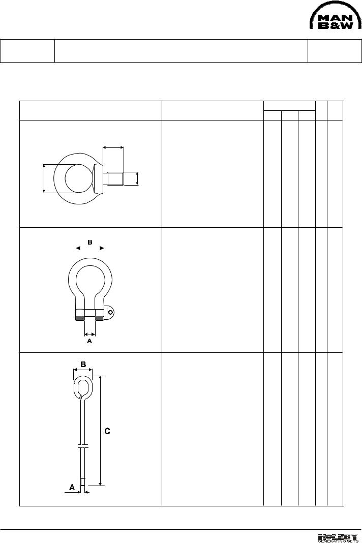
Eye screw for lifting of piston. M12 ø30 20.5

C

B

A


Shackle for lifting of piston.

28 60


Eye bolt for piston lift at check

of connecting rod big-end M12 54 410 bearing.

08028-0D/H5250/94.08.12

S/E

Item

No


S 021

S 033

S 070

S = Standard E = Extra

01.17 - ES0

52006-06H Tools for Piston , Connecting Rod and Cylinder Liner

Plate

Page 2 (6)

L23/30H

Illustration of Tools Designation

Dimensions

A B C

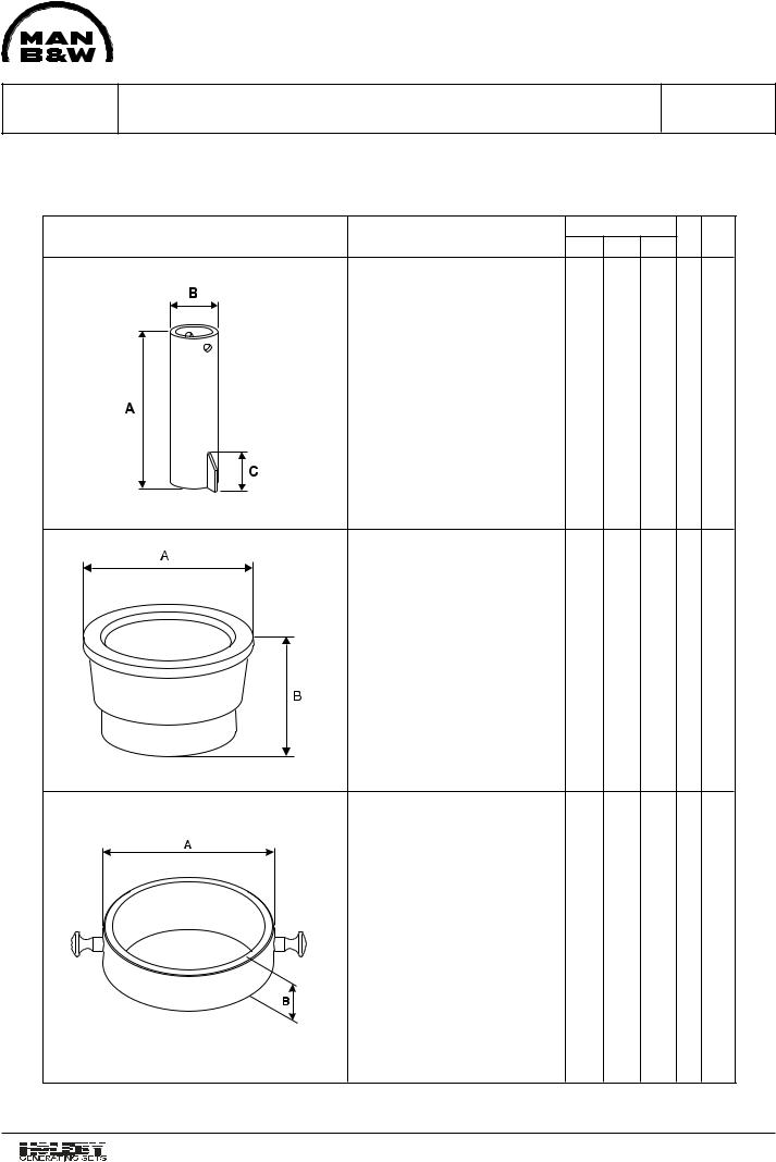
Back stop for cylinder liner,


2 pieces.

280 ø 60.3 75

Guide ring for mounting of piston. ø 298 110

Only for 900 rpm.

Guide ring for mounting of piston. ø 275 85

Only for 720/750 rpm

S/E

Item

No


S 094

S 116

S 117

08028-0D/H5250/94.08.12

S = Standard E = Extra

01.17 - ES0

08028-0D/H5250/94.08.12

Plate

Tools for Piston , Connecting Rod and Cylinder Liner 52006-06H

Page 3 (6)

L23/30H

Illustration of Tools

Designation

Dimensions

S/E

Item

A

B

C

No


Piston ring opener.

105

260


S 141


Testing mandrel for piston ring


and scraper ring grooves.


Grooves for piston ring.

4.43

S

153

A


Grooves for scraper ring.

7.43

S

165


A

Plier for piston pin lock ring.

550 25 ø 3.5 S 200

B

C

Torque spanner

20-120 Nm

463

½ "

S

261

A


Torque spanner

80-360 Nm

718

¾ "

S

273

B


S = Standard E = Extra

01.17 - ES0

52006-06H Tools for Piston , Connecting Rod and Cylinder Liner

Plate

Page 4 (6)

L23/30H

Illustration of Tools Designation

Dimensions

A B C

Socket.

24 55 ¾ "

Pneumatic impact spanner

3/4"

Lifting tool for cylinder liner.

370 930

S/E

Item

No


S 381

E 415

S 452

08028-0D/H5250/94.08.12

S = Standard E = Extra

01.17 - ES0

08028-0D/H5250/94.08.12

Plate

Tools for Piston , Connecting Rod and Cylinder Liner 52006-06H

Page 5 (6)

L23/30H

Illustration of Tools

Dimensions

S/E

Item

Designation

B

C

No


A


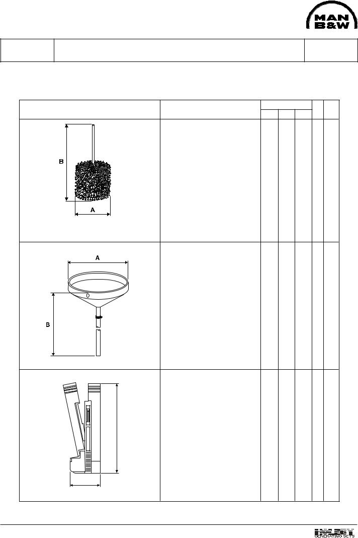
Honing brush incl. woodenbox ø 228

850


S 488

Wooden box

L x B x H = 269 x 269 x 250 mm

Funnel for honing of cylinder


liner.

ø 258 1615

S 511

Magnifier (30 x).

140 50

S 559

A

B

S = Standard E = Extra

01.17 - ES0

Соседние файлы в папке MAN-BW L23-30 (ЧН 225_300)+