

7 семестр (Бормотов А) / 1man_bw_l23_30_chn_23_30_instruktsiya_po_ekspluatatsii / MAN-BW L23-30 (ЧН 225_300)+ / MAN-BW L23-30 H Vol-1 (Instruction)+
.pdfWorking Card |
Function of the Hydraulic Tools |
520-01.05 |
Page 1 (7) |
Edition 02 |
|
|
|
|
|
|
|
|
|
General |
08028-0D/H5250/94.08.12
Safety precautions |
Special tools |
|
|
Stopped engine |
Plate no |
Item no |
Note |
Shut-off starting air |
|
|
|
Shut-off cooling water |
|
|
|
Shut-off fuel oil |
|
|
|
Stopped lub. oil circul. |
|
|
|
Press Blocking - Reset |
|
|
|
Description |
Hand tools |
|
|
Safety hints and function of hydraulic tools. |
|
|
|
Starting position
Application of hydraulic tools |
520-01.06 |
Related procedure
Manpower |
|
|
Replacement and wearing parts |
||
Working time |
: |
hours |
Plate no |
Item no |
Qty/ |
Capacity |
: |
men |
|
|
|
Data |
|
|
|
|
|
Data for pressure and tolerance |
(Page 500.35) |
|
|
||
Data for torque moment |
|
(Page 500.40) |
|
|
|
Declaration of weight |
|
(Page 500.45) |
|
|
|
99.43 - ES0

520-01.05 |
Function of the Hydraulic Tools |
Working Card |
Edition 02 |
Page 2 (7) |
|
|
|
|
|
|
|
General
Function of the Bolt Tensioning Device
In order to achieve an optimal result with one or several devices, some rules have to be considered. We expressly point out that a conscientious handling of the device as well as the accessories is of highest importance. To ignore these rules or separate hints means danger to life or danger of injuries! See Safety Hints.
Safety Hints
Beside regarding the general accident-prevention rules, the safe handling of the device and the hydraulic accessories demand especially the consideration of the following hints. When disregarding even single items, you can cause danger to life and/or danger of injuries!
1.When leakages occur during the pressurization, bleed pressure immediately and seal the leakage or replace defect parts.
2.In case of repair, use exclusively original spare parts. Inexpert substitution of damaged parts by non-original spare parts is prohibited.
3.All assembly parts are to be handled in correspondence to the working cards only. A change in the procedure or another operation of the device is not allowed.
4.Make sure that the components to be tensioned do not exceed the admissible strain.
5.In order to use the device, the thread has to be sufficiently exceeding in order to avoid that the turn of a thread cracks, see item 4.
6.During the pressurization the people involved have to remain in an appropriate distance. Staying in direction towards the bolt axis is forbidden.
7.Tensioning pressures or tensioning forces are to be given or changed by authorized personnel only while considering the admissible component loads, see item 4.
8.The operation and handling of the device are to be carried out by expert staff only.
9.The given max. operation pressure is not to be exceeded in any case and is to be watched at the manometer of the pressure generator during the complete tensioning or loosening procedure. When having achieved the given pressure, stop the pressurization immediately.
10.During the pressurization when tensioning or loosening the bolt connection, always watch the admissible stroke of the device. Exceeding this stroke is connected with insufficient generating of tensioning force because the device is tensioned in itselve or the hydraulic pressure is bleeded automaticly.
11.On principle, when connecting high-pressure hoses it has to be taken care that the connections are correct (see also separate hints).
12.The hydraulic hoses have to be installed in a way that they are not run over by vehicles or unnecessarily walked over by people. Never lay hoses across sharp objects (danger of cuts) and never bend or jam them in.
13.Never hold or transport the device by using the high-pressure hoses.
14.An incorrect working manometer that doesn´t show the right pressure leads to overstressing of the parts and to an incorrect bolt connection. Apart from damaged parts an incorrect bolt connection can also cause conditions that are danger to life. Therefore take care that the manometer shows the right value or the tensioning force is checked in an other way (for example by using a master manometer). Tensioning forces can be checked for example by measuring the linear deformation. Damaged manometers have to be exchanged immediately.
08028-0D/H5250/94.08.12
99.43 - ES0

Working Card |
|
Function of the Hydraulic Tools |
520-01.05 |
||
Page 3 (7) |
|
Edition 02 |
|||
|
|
|
|
|
|
|
|
|
|
General |
|
Working Hints |
|
|
|
|
|
|
|
|
|
||
08028-0D/H5250/94.08.12
In order to achieve a bolt connection of high precision, it is vital to consider the following working hints:
-Prior to setting the device, clean all threads and remove possible damages in order to avoide a “freeze on”.
-The base plate for the device must be plain and free of dirt. Further check the squareness towards the bolt axis in order to avoid that the bolt has a bending stress during the pressurization (tensioning).
-The stroke of the device may not at any point be exceeded.
-For transporting the device it is necessary to uncouple all high-pressure hoses.
-After each pressurization, bring the device back to zero, see also Piston Return Stroke.
Turnable Connection Unit
In order to simplify the connection of the hydraulic hose, a turnable connection unit is mounted on some devices.
The turnable connection unit consists of the following components:
-bolt nipple
-disc
-seal
-securing ring
Furthermore, an entry guide is available or contained in the scope of supply, see fig.1.
Fig. 1. Turnable connection unit.
Exchange of the Seals
Should leakages show up at the connection unit, it might be necessary to exchange the seals.
For doing so, loosen the securing ring and take the disc off the bolt nipple. Having removed the seals, clean the components with fluff-free cleaning material. You can also apply compressed air. Having checked the components for damages and oiled them slightly, apply new seals by help of the entry guide and reassemble the turnable connection unit.
Hint: - For the cleaning, never use aggressive cleaning liquids.
-For oiling the parts, use exclusively hydraulic oil.
-For replacements, use exclusively new seals.
Coupling of the High-Pressure Hoses
-Only couple when the hydraulic system is in a pressureless condition.
-To produce a high-pressure connection, put one coupling and one nipple into each other while the coupling socket is pulled back. When letting the coupling socket go, there is a form fit barring the connection.
99.43 - ES0

520-01.05 |
Function of the Hydraulic Tools |
Working Card |
Edition 02 |
Page 4 (7) |
|
|
|
|
|
|
|
General |
|
|
-By drawing the hose with a manual force of about 100 N make sure that the connection is correctly barred.
-For decoupling the high-pressure hose in a pressureless condition, first pull back the coupling socket and then take off the hose.
Fig. 2. Coupling of the high-pressure hoses.
If necessary, turn back the device, but make sure that the max. admissible stroke of the device is not exceeded. Beside that, it has to be ensured that the cylinder and the support sleeve remain centrically towards each other (consider centering shoulder).
Having made all hydraulic connections correctly, see fig. 2, start the pressurization for the tensioning procedure. If the necessary pressure is achieved stop pressurization. The inducted force causes the bolt to extend or an edging of the components to be tensioned so that the main nut is lifted from the flange. Screw it back to the flange, see fig. 3. Check by help of a feeler gauge leaf whether the main nut really fits tight to the flange. After that, bleed hydraulic pressure. Now the connection is tensioned.
Hoses with fast-lock coupling sockets avoid, also when uncoupled, that oil runs out. When the hoses get heated, there can be an inside pressure in the uncoupled condition making a coupling impossible. By loosening one screw connection (see fig. 2) the pressure can be bleeded
-To avoid a contamination use protecting caps for the sockets.
Tensioning Procedure
Prior to the tensioning procedure make sure that the components to be tensioned are correctly positioned towards each other. Then screw the device onto the bolt.
First put the support sleeve on the bolt and align it centrically to the bolt axis. When screwing on the device take care that the support sleeve at the cylinder is correctly centered (consider centering shoulder).
Screw the device until the support sleeve or the support cylinder fits exactly to the flange. The piston of the device must be at its zero position. Furthermore, take care that the hydraulic connector and the window for the adjusting rod is well accessible.
Having brought the piston to its zero position, see fig. 4, the hydraulic hoses can be decoupled. In order to prevent impurities, it is advisable to close coupling sockets and coupling nipples at once by protecting caps. The device can be unscrewed from the bolt.
ÞAlways consider the safety and working hints!
Loosening Procedure
In order to loosen an existing bolt connection, screw the device onto the bolt. First put the support sleeve on the bolt and align it centrically to the bolt axis. When screwing on the device take care that the support sleeve at the cylinder is correctly centered (consider centering shoulder).
The piston of the device must be at its zero position. Having screwed the device down until the support sleeve or the support cylinder fits tight to the flange, turn back the device by at least the value (slit measure) which the bolt and the components spring back elastically during the loosening procedure.
Hint: The adjusted slit measure may never exceed the admissible stroke of the device! Furthermore, take care that the window for the adjusting rod are well accessible.
Having made all hydraulic connections correctly, see fig. 2, start the pressurization.
08028-0D/H5250/94.08.12
99.43 - ES0

Working Card |
Function of the Hydraulic Tools |
520-01.05 |
Page 5 (7) |
Edition 02 |
|
|
|
|
|
|
|
|
|
General |
08028-0D/H5250/94.08.12
During the pressurization, a slight turn-back momentum is applied to the main nut with the adjusting rod. At the moment, when the main nut can be loosened, interrupt the pressurization. Should it not be possible to loosen the main nut when achieving the original tensioning pressure, interrupt the pressurization immediately. Find the cause with expert staff.
Having achieved the loosening pressure, turn back the main nut by the value that the bolt and the components spring back during the loosening procedure. The slit measure, however, must be lower than the slit measure adjusted at the device before, see also hint b.
The main nut may never be turned back until it fits to the piston or the cylinder since then the device can be tensioned in itself.
Having turned back the main nut, the pressure can be bled. The bolt connection is loosened. Before unscrewing the device, bring the piston back to its zero position, see fig. 4. After that, the hydraulic hoses can be decoupled. In order to prevent impurities, it is advisable to close coupling sockets and coupling nipples at once by protecting caps. The device can be unscrewed from the bolt.
ÞMake sure that no operational forces (e.g. inner pressure) affect the components to be loosened since only part of the bolts take over these forces and thus the bolts, which are not yet loosened, might be overburdened.
ÞThe pressure when the main nut can be loosened may never exceed the tensioning pressure by help of which the connection was tensioned! Should it not be possible to loosen the main nut when reaching the original tensioning pressure interrupt the pressurization immediately. Find the cause with expert staff.
ÞAlways consider the safety and working hints!
Hint:
a)Should it be impossible to unscrew the device after the depressurization, it has been turned back by a too low measure prior to the pressurization. Pressurize again until the original tensioning pressure is reached, turn the main nut and bleed the pressure again (tensioning procedure). Now you can turn back the device further. (Attention: consider the admissible stroke of the device!) Now repeat the loosening procedure explained above.
b)Should it be impossible to loosen the main nut after the depressurization, it has been turned back by a too low measure prior to the pressurization. Pressurize again and turn the main nut further back. Bleed the pressure again.
Hint: Never screw the main nut back until it fits to the piston since the device can be tensioned in itself.
Adjustment and Turn Back of the Main Nut
During the pressurization of the device, the bolt is being extended by the tensioning force and the components are being edged. The result is that the main nut does no longer fit to the flange.
Having achieved the necessary pressure, adjust the main nut - when tensioning - until it fits to the flange again before bleeding the pressure, see Tensioning Procedure. When loosening the bolts, turn back the main nut after the pressurization according to the bolt and component deformations, (see Loosening Procedure.
Hint: During the loosening procedure, never turn back the main nut until it fits to the piston or the cylinder since the main nut sticks after the depressurization.
The main nut is equipped with several radial bores where the adjusting rod can be put in. The main nut is accessible through the window in the support sleeve.
99.43 - ES0

520-01.05 |
Function of the Hydraulic Tools |
Working Card |
Edition 02 |
Page 6 (7) |
|
|
|
|
|
|
|
General |
|
|
Fig. 3 Adjustment and turn back of the main nut.
Piston Return Stroke
After each pressurization it must be ensured that the piston of the device is brought back to its zero position. On principle, it has to be considered that hydraulic oil is being displaced from the piston area. In order to enable the oil to flow back to the tank of the pressure generator, the corresponding hydraulic connections must be done.
The piston return stroke is done by a screw-down at the bolt itself before the device is taken off.
Hint: When using fast lock coupling elements, the oil’s running out and thus a piston return stroke in an uncoupled condition is impossible!
During the piston return stroke, considerable backpressures can occur in the piston area of the device since quite large quantities of oil have to flow back through the small cross sections of the high-pres- sure connections.
In order not to unnecessarily increase the force for the piston return stroke turn the piston slowly. On principle the piston of the device has to be pushed back until it fits to the cylinder again.
Exchange of the Seals
Should leakages occur at the piston of the device, an exchange of the seals might be necessary.
Drive out the piston by carefully beating with a hammer while using a plastic spacer in order to protect the device from unnecessary damages. After removing the hydraulic connector, you can also carefully lead compressed air into the piston area.
Attention: Sudden input of compressed air can lead to the piston’s uncontrolled outlet.
After removal of the piston, the seals and the backup rings can be removed from the piston and the cylinder.
Carefully clean the components with fluff-free material and check them for damages. If necessary, use compressed air for the cleaning, but never aggressive cleaning liquids. After that, slightly oil these components with hydraulic oil and assemble new backup rings as well as new seals to the piston and the cylinder according to the drawing.
08028-0D/H5250/94.08.12
Fig. 4. Piston return stroke.
Fig. 5. Exchange of the seals.
99.43 - ES0

Working Card |
Function of the Hydraulic Tools |
520-01.05 |
Page 7 (7) |
Edition 02 |
|
|
|
|
|
|
|
|
|
General |
08028-0D/H5250/94.08.12
As shown in the picture, first assemble the backup ring, then put the seal onto the backup ring. Piston and cylinder can now be assembled again by putting the components together. By slightly hammering on the piston (with plastic spacer), it can be driven in until it fits tightly to the cylinder (piston in its zero position). It is essential that the piston does not tilt during being driven in since this might damage the seals as well as the components. When assembling the piston it has to be taken care that the air can come out of the piston area.
Maintenance and Storage
Regular maintenance of the device is not necessary, but you should consider the following points:
a) Storage
After each operation, repair possible damages and clean the device in order for it to be ready for the next operation immediately. In order to avoid a corrosion it is advisable to oil the device and especially its thread. All coupling nipples, coupling sockets and also loosened screw connections are to be closed by protecting caps.
In addition, check the components of the device and its accessories for completion.
Keep the device in the tool box also offering protection from mechanical damages.
The temperature must be between -20 C and +70 C in order to exclude a damage of the seals.
b) Start-up of the device
Prior to the device’s operation, repair possible damages and clean the device.
Check the components of the device and its accessories for completion.
The operating manual has to be read by all users.
99.43 - ES0

Working Card |
Application of Hydraulic Tools for Connecting Rod |
520-01.06 |
Page 1 (2) |
Edition 03H |
|
|
|
|
|
|
|
|
|
L23/30H |
08028-0D/H5250/94.08.12
Safety precautions |
Special tools |
|
|
|
|
Stopped engine |
Plate no |
Item no |
Note |
|
||||
|
Shut-off starting air |
|
|
|
|
|
|
|
|
|
Shut-off cooling water |
See page 2 |
|
|
|
|
|
||
|
Shut-off fuel oil |
|
|
|
|
|
|
|
|
|
Stopped lub. oil circul. |
|
|
|
|
|
|
|
|
|
Press Blocking - Reset |
|
|
|
|
|
|
|
|
Description |
Hand tools |
|
|
|
Application of hydraulic tools for connecting rod. |
|
|
|
|
Starting position
Function of hydraulic tools |
520-01.05 |
Related procedure
Manpower |
|
|
Replacement and wearing parts |
||
Working time |
: |
hours |
Plate no |
Item no |
Qty/ |
Capacity |
: |
men |
|
|
|
Data |
|
|
|
|
|
Data for pressure and tolerance |
(Page 500.35) |
|
|
||
Data for torque moment |
|
(Page 500.40) |
|
|
|
Declaration of weight |
|
(Page 500.45) |
|
|
|
00.20 - ES0
520-01.06 |
Application of Hydraulic Tools for Connecting Rod |
Working Card |
Edition 03H |
Page 2 (2) |
|
|
|
|
|
|
|
L23/30H |
|
|
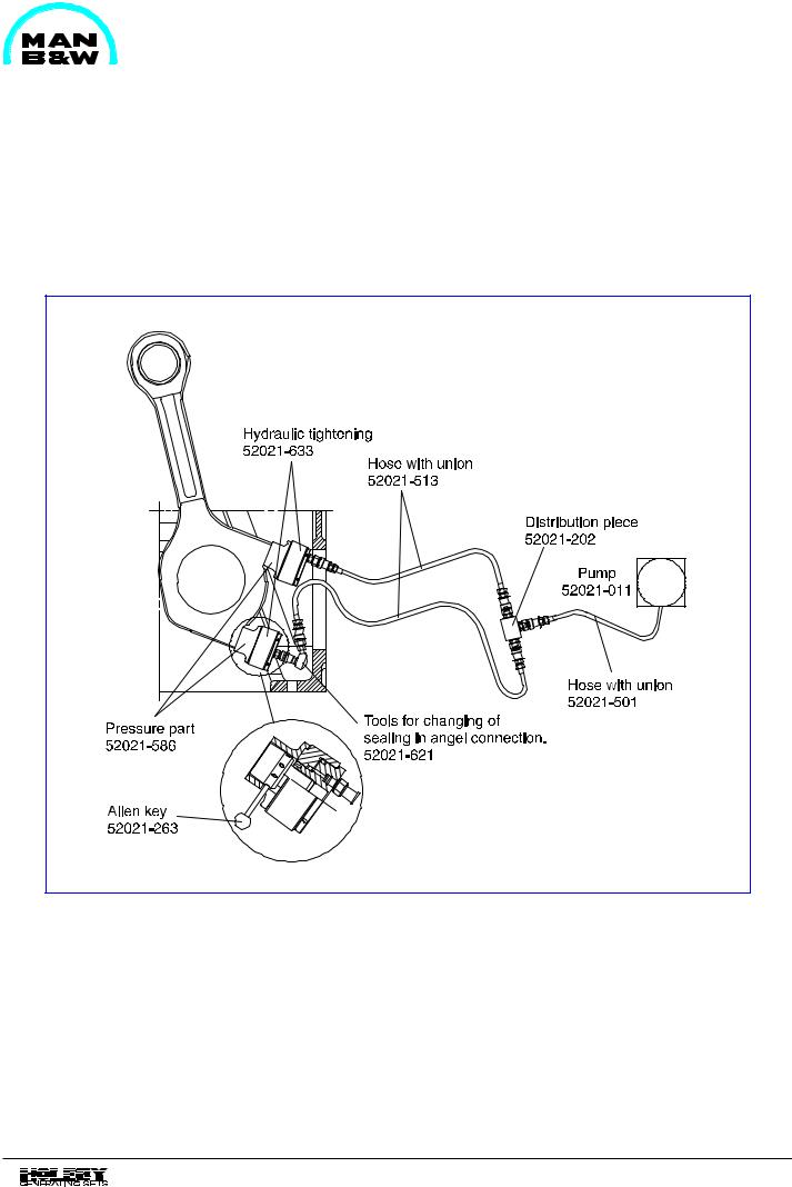
This working card gives the information for application of hydraulic tools, to be used in connection with working card 520-01.05.
Fig 1 Connecting rod.
08028-0D/H5250/94.08.12
00.20 - ES0

Working Card |
Application of Hydraulic Tools |
520-01.06 |
Page 1 (2) |
for Cylinder Head and Main Bearing |
Edition 04H |
|
|
|
|
|
|
|
|
L23/30H |
08028-0D/H5250/94.08.12
Safety precautions |
Special tools |
|
|
|
|
Stopped engine |
Plate no |
Item no |
Note |
|
||||
|
Shut-off starting air |
|
|
|
|
|
|
|
|
|
Shut-off cooling water |
See page 2 |
|
|
|
|
|
||
|
Shut-off fuel oil |
|
|
|
|
|
|
|
|
|
Stopped lub. oil circul. |
|
|
|
|
|
|
|
|
|
Press Blocking - Reset |
|
|
|
|
|
|
|
|
Description |
Hand tools |
|
|
|
Application of hydraulic tools for cylinder head |
|
|
|
|
and main bearing. |
|
|
|
|
Starting position
Function of hydraulic tools |
520-01.05 |
Related procedure
Manpower |
|
|
Replacement and wearing parts |
||
Working time |
: |
hours |
Plate no |
Item no |
Qty/ |
Capacity |
: |
men |
|
|
|
Data |
|
|
|
|
|
Data for pressure and tolerance |
(Page 500.35) |
|
|
||
Data for torque moment |
|
(Page 500.40) |
|
|
|
Declaration of weight |
|
(Page 500.45) |
|
|
|
00.20 - ES0