Скачиваний:
225
Добавлен:
14.07.2019
Размер:
7.68 Mб
Скачать

506-01.00

Dismounting of Piston and Connecting Rod

Working Card

Edition 01H

Page 2 (3)


L23/30H

Preparations before Dismounting

1) Clean the upper part of the cylinder. If not, the piston may get stuck during removal in the carbon deposited in this area.

a)Turn the piston to the buttom.

b)Place a used piston ring on top of the piston.

c)Mount the tube (for holding down the cylinder liner during the piston withdrawal) on one of the cylinder head studs, screw on the nut and tighten it slightly.

d)Turn the piston in top, in order to push the flame ring out of the cylinder by means of the piston ring.

Info: It is the used piston ring which pushes the flame ring out of the cylinder.

2)Remove the gangway, if any installed, in order to improve the access conditions.

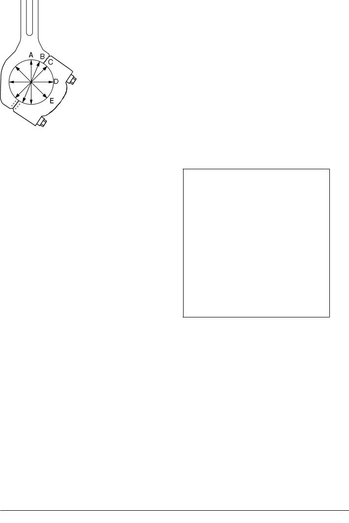
3)Turn the crankshaft to bring the crank throw concerned into a position of approx. 50 degrees before TDC.

This position is identifiable by the connecting rod shaft being very close to the cylinder liner shirt, see fig. 1.

4)Clean the threaded hole in the piston top, and mount the eye screw.

5)Mount the tube (for holding down the cylinder liner during the piston withdrawal) on one of the cylinder head studs, screw on the nut and tighten it slightly.

6)Attach a wire rope to the eye bolt by means of a shackle, hook the wire on to a tackle and pull the wire rope tight.

Note! If minor adjustments of the crank throw position appear necessary for access to the connecting rod screws, the wire rope must be slackened before turning of the crankshaft and tightened up again in the new crank throw position.

08028-0D/H5250/94.08.12

Fig 1. Mounting of tools (placing).

Fig 2. Removal of bearing cap.

96.20 - ES0S

Working Card

Dismounting of Piston and Connecting Rod

506-01.00

Page 3 (3)

Edition 01H


L23/30H


Fig 3. Removal of upper big-end bearing shell.

Dismounting of Bearing Cap

7)Unload the connecting rod screws and unscrew one of the upper screws.

8)Mount the guide pin for the bearing cap in one of the threaded holes and fit a screwdriver or similar in the hole in the guide pin, and unscrew the screws.

Fig 4. Lift of piston and connecting rod assembly.

08028-0D/H5250/94.08.12

Note! The purpose of the guide pin is to prevent any damage of crank journal, joint faces or bearing surface to occur during dismounting of the bearing cap, and to facilitate easy handling when removing the bearing cap from the crankcase.

9)Remove the screwdriver from the guide pin, and dismount the bearing cap by sliding it along the guide pin, see fig 2.

10)Remove the guide pin from the connecting rod.

Dismounting of Upper Big-end Bearing Shell

11)Pull the piston and connecting rod assembly upwards and remove the upper big-end bearing shell, see fig 3.

12) Lift the piston and connecting rod assembly up through the cylinder liner and out of the engine, see fig 4.

96.20 - ES0S

Working Card

Separation of Piston and Connecting Rod

506-01.05

Page 1 (2)

Edition 01H


L23/30H

08028-0D/H5250/94.08.12

Safety precautions:

Stopped engine

Shut-off starting air

Shut-off cooling water

Shut-off fuel oil

Shut-off cooling oil

Stopped lub. oil circul.

Description:

Separation of piston and connecting rod for inspection or/and overhaul.

Assembly of piston and connecting rod after inspection or/and overhaul.

Starting position:

Piston and connecting rod are dismounted

from engine

506-01.00

Related procedure:


Inspection or/and overhaul of piston

506-01.10

Inspection or/and overhaul of


connecting rod

506-01.15

Inspection of connecting rod


big-endbearing

506-01.16

Manpower:


Working time

:

1/4

hour

Capacity

:

1

man

Data:


Data for pressure and tolerance

(Page 500.35)

Data for torque moment

(Page 500.40)

Declaration of weight

(Page 500.45)

Special tools:


Plate no

Item no

Note

52006

021


52006

033


52006

200


Hand tools:

Open-end spanner, 24 mm.

Wooden wedge, 2 pieces.

Wooden support.

Wire.

Replacement and wearing parts:

Plate no

Item no

Qty/

95.50 - ES0S

506-01.05

Separation of Piston and Connecting Rod

Working Card

Edition 01H

Page 2 (2)


L23/30H

Landing of Piston and Connecting Rod

1) Land the piston and connecting rod carefully on wooden supports to prevent damage of piston and scraper ring, see fig 1.

6) Take out the securing ring, (seeger circlips), push out the piston pin and lift the connecting rod away.

Assembly of Piston and Connecting Rod

7)For assembly of piston and connecting rod, see point 1-6 in reversed order.

8)Lubricate the piston pin before assembling.

Fig 1. Landing of Piston and Connecting Rod.

2) The bearing cap should be mounted with the screws tightened only by hand, in order to protect the serrated joint faces during handling of the assembly, see fig 1.

3) Remove the shackle and eye screw from the piston crown, see fig 1.

4) Place the piston and connecting rod assembly in upright position resting on the top face of the piston crown, see fig 2.

Note: Wooden wedges should be used to prevent the connecting rod from swinging out and thus impact the piston skirt during the lifting into upright position.

5) Place a wire around the big-end of the connecting rod. Attach a tackle and tighten the wire rope, see

fig 2.

Fig 2. Removal of Connecting Rod and Piston Pin.


Separation of Piston and Connecting Rod


08028-0D/H5250/94.08.12

95.50 - ES0S

Working Card

Piston

506-01.10

Page 1 (4)

Edition 01H


L23/30H

08028-0d/H5250/94.08.12

Safety precautions:

Stopped engine

Shut-off starting air

Shut-off cooling water

Shut-off fuel oil

Shut-off cooling oil

Stopped lub. oil circul.

Description:

Cleaning and inspection of piston. Control of piston ring, scraper ring and ring grooves.

Starting position:


Piston has been dismantled from


connecting rod

506-01.05

Related procedure:


Mounting of piston and


connecting rod

506-01.20

Manpower:


Working time

:

1/2

hour

Capacity

:

1

man

Data:


Data for pressure and tolerance

(Page 500.35)

Data for torque moment

(Page 500.40)

Declaration of weight

(Page 500.45)

Special tools:


Plate no

Item no

Note

52006

141


52006

153


52006

165


Hand tools:

Tools for cleaning of piston, steel brush, scraper etc.

Replacement and wearing parts:

Plate no

Item no

Qty/

95.50 - ES0S

506-01.10

Piston

Working Card

Edition 01H

Page 2 (4)


L23/30H

Removal of Piston Ring

For removal of piston rings, which are to be used again, and for all mounting of rings, only the special ring opener which prevents local over stressing of the rings should be used.

Straps to expand the ring gap or tools working on the same principle must not be used, as this would result in permanent deformation which might cause blowby or broken rings.

Inspection of Piston

1)Remove the piston and scraper rings.

2)Cleanandexaminethepistonringstodetermine if reuse is acceptable, see page 3.

3)Clean the piston on the outside and on the inside.

4)Inspect the piston ring and scraper ring grooves for wear, see page 3.

08028-0d/H5250/94.08.12

95.50 - ES0S

Working Card

Piston

506-01.10

Page 3 (4)

Edition 01H


The piston has to be scrapped if:

A) The wear limit on the testing mandrel is exceeded, see fig 1A

or

B) The clearance between the new piston/scraper ring and ring groove is exceeded, see fig 1B.

Note! At each piston overhaul:

-The piston and scraper ring must be exchanged.

-The cylinder liner must be honed according to the instructions.

L23/30H


Piston and oil

New ring

Ring grooves.


scraper ring.

grooves.


Max. wear limit.


Nominal size.

Tolerances.


Piston ring

New

4.0 mm

+0.14

4.43 mm

1

4.0 mm

+0.12


Piston ring

New

4.0 mm

+0.11

4.43 mm

2

4.0 mm

+0.09


Piston ring

New

4.0 mm

+0.11

4.43 mm

3

4.0 mm

+0.09


Scraper ring

New

7.0 mm

+0.10

7.43 mm


7.0 mm


+0.08


Table 1. Nominal size, new ring groove tolerance and wear limit for ring grooves.

A) Testing Mandrel for Ring Grooves

B) Clearance Ring/Groove

08028-0d/H5250/94.08.12

If the wear limit (2 mm mark) on the testing mandrel is exceeded, the specified max. wear limits are exceeded, and the piston must be scrapped.

Wear limit line.

The handle is marked with the nominal size.

0.45 mm

Maximum vertical clearance between new piston ring/scraper ring and ring groove: 0.45 mm.

Fig 1. Wear limits for ring grooves.

95.50 - ES0S

506-01.10

Piston

Working Card

Edition 01H

Page 4 (4)


L23/30H

Position of Piston and Scraper Rings

Piston Ring No 1: marked with ident. No "top 881500-3" or "0946".

Piston Ring No 2: marked with ident. No "top 881502-7" or "0947".

Piston Ring No 3: marked with ident. No "top 881501-5" or "0945".

Scraper ring: marked with ident. No "top 881503-9" or "0120".

Marking of Piston and Scraper Rings

Marking

Identification marks to face upwards against the piston crown when mounted.

Note! The marking may include other figures than mentioned above, for instance trade mark and production codes.

08028-0d/H5250/94.08.12

95.50 - ES0S

Working Card

Connecting Rod

506-01.15

Page 1 (4)

Edition 01H


08028-0D/H5250/94.08.12

L23/30H

Safety precautions:

Special tools:


Stopped engine

Plate no

Item no

Note

Shut-off starting air


Shut-off cooling water

52006

273

80-360 Nm

Shut-off fuel oil

52006

618

225-250 Nm

Shut-off cooling oil


Stopped lub. oil circul.


Description:

Cleaning, inspection and test measurement of connecting rod.


Hand tools:

Starting position:

Inside micrometer (195 mm).


Feeler gauge 0.15 - 0.20 mm.

Connecting rod has been


dismantled from piston

506-01.05

Related procedure:


Mounting of piston and


connecting rod

506-01.20

Manpower:


Replacement and wearing parts:

Working time

:

1/2

hour

Plate no

Item no

Qty /

Capacity

:

1

man


Data:


Data for pressure and tolerance

(Page 500.35)


Data for torque moment


(Page 500.40)


Declaration of weight


(Page 500.45)


95.50 - ES0S

506-01.15

Connecting Rod

Working Card

Edition 01H

Page 2 (4)


L23/30H

Cleaning of Connecting Rod

1.Clean all machined surfaces on the connecting

rod.

2.Degrease the serrated joint faces, tapped holes and connecting rod screws with a volatile solvent and blow dry with working air.

Visual Inspection of Serrated Faces

3.Inspect the serrated joint faces.

Damages, in the form of visible wear marks and pittings or even cracks, may be in the serration due to relative movements between the surfaces.

Wear marks and cracks are visible, but not perceptible with a fingernail. Pittings and impact marks are both visible and perceptible.

Note!! Handle the connecting rod with care. In case of damaged serration caused by improper handling, the bearingcapcannolongerbetightenedtotheconnecting rod without ovalness of the big-end bore.

4.Register observed damages in the scheme

"Connecting Rod Inspection" for historic use only. See page 4.

5.Carefully smooth single raised spots in the serration caused by pitting and impact marks with a filesmall.

Inspection of Connecting Rod Screws

6.Inspect the connecting rod screws for seizures in the threads and pittings on the contact surfaces of the screwheads.

7.Turn the connecting rod screws into bottom position in the threaded screw holes by hand.

If screws

Then


have seizures in

Renew the screws

threads or pittings on


contact surface


cannot be turned into

Renew the screws

bottom position by hand


Measurement of Big-end Bore

For check of ovalness the bearing cap has to be mounted onto the big-end bore without bearing shells.

Note !! The ident. No on the connecting rod and the bearing cap must always be the same, see fig 3.

8.Mount the bearing cap onto the connecting rod

Fig. 1. Point of measurement

by means of the connecting rod screws.

9.Tighten the screws with the prescribed torque, see working card 506-01.25.

10.Measure five different diameters in the middle of the boring, see fig 1.

11.Register the measurements in the scheme "Connecting Rod Inspection". See page 4.

12.Calculate the maximum ovalness as the difference between biggest and smallest diameter measured.

13.Check if maximum ovalness is exceeded, see page 500.35.

If

Then

08028-0D/H5250/94.08.12

95.50 - ES0S

Соседние файлы в папке MAN-BW L23-30 (ЧН 225_300)+