

7 семестр (Бормотов А) / 1man_bw_l23_30_chn_23_30_instruktsiya_po_ekspluatatsii / MAN-BW L23-30 (ЧН 225_300)+ / MAN-BW L23-30h project-guide
.pdf1683390-5.0 Page 1 (1)
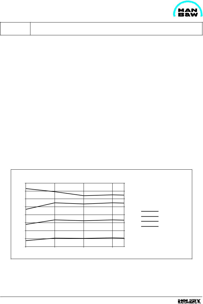
Heat Balance |
D 10 20 0 |
|
|
L23/30H
P = 135 kW/cyl. at 750 RPM. Pme = 18.1 bar
Ambient cond. 45.0 C - 1.00 bar - Cool W 36.0 C with engine driven pumps: Lub. oil, HT Water
(Generator load, const. RPM)
Exhaust gas |
Jacket cooling/Ch. air |
|
Lub. oil/Radiation |
|
kW/cyl. |
110 |
|
|
|
|
|
55.0 |
|
|
|
|
|
||||
105 |
|
|
|
|
52.5 |
||
|
|
|
|
||||
100 |
|
|
|
|
50.0 |
||
|
|
|
|
||||
95 |
|
|
|
|
47.5 |
||
|
|
|
|
||||
90 |
|
|
|
|
|
45.0 |
|
|
|
|
|
||||
85 |
|
|
|
|
42.5 |
||
|
|
|
|
||||
80 |
|
|
|
|
|
40.0 |
|
|
|
|
|
||||
75 |
|
|
|
|
|
37.5 |
|
|
|
|
|
||||
70 |
|
|
|
|
|
35.0 |
|
|
|
|
|
||||
65 |
|
|
|
|
|
32.5 |
|
|
|
|
|
||||
60 |
|
|
|
|
|
30.0 |
|
|
|
|
|
||||
55 |
|
|
|
|
|
27.5 |
|
|
|
|
|
|
|||
50 |
|
|
|
|
|
25.0 |
|
|
|
|
|
||||
45 |
|
|
|
|
|
22.5 |
|
|
|
|
|
||||
40 |
|
|
|
|
|
20.0 |
|
|
|
|
|
|
|||
35 |
|
|
|
|
|
17.5 |
|
|
|
|
|
||||
30 |
|
|
|
|
|
15.0 |
|
|
|
|
|
||||
25 |
|
|
|
|
|
12.5 |
|
|
|
|
|
||||
20 |
|
|
|
|
|
10.0 |
|
|
|
|
|
||||
15 |
|
|
|
|
|
7.5 |
|
|
|
|
|
||||
10 |
|
|
|
|
|
5.0 |
|
|
|
|
|
||||
5 |
|
|
|
|
|
2.5 |
|
|
|
|
|
||||
0 |
|
|
|
|
|
0.0 |
|
|
|
|
|
||||
|
|
|
Charge air |
|
|
|
Exhaust gas* |
|
|
|
Jacket cooling |
|
|
|
Lubricating oil |
|
|
|
Radiation |
25.0 |
50.0 |
75.0 |
100.0 % Load |
33.8 |
67.5 |
101.3 |
135.0 kW/cyl. |
* tolerance ±10%
01.01

1624434-2.1 Page 1 (1)
Heat Balance |
D 10 20 0 |
|
|
|
|
|
|
P = 160 kW/cyl. at 900 RPM. Pme = 17.9 bar |
|
|
Ambient cond. 27.0 C - 1.00 bar - Cool W 27.0 C (Generator load, const. RPM) |
||
Exhaust gas |
|
Jacket cooling/Ch. air |
||
|
|
|
Lub. oil/Radiation |
|
|
kW/cyl. |
|||
120 |
|
|
|
60 |
|
|
|
||
110 |
|
|
|
|
|
|
|
55 |
|
|
|
|
||
100 |
|
|
|
|
|
|
|
50 |
|
|
|
|
||
90 |
|
|
|
|
|
|
|
45 |
|
|
|
|
||
80 |
|
|
|
|
|
|
|
40 |
|
|
|
|
||
70 |
|
|
|
|
|
|
|
35 |
|
|
|
|
||
60 |
|
|
|
|
|
|
|
30 |
|
|
|
|
||
50 |
|
|
|
|
|
|
|
25 |
|
|
|
|
||
40 |
|
|
|
|
|
|
|
20 |
|
|
|
|
||
30 |
|
|
|
|
|
|
|
15 |
|
|
|
|
||
20 |
|
|
|
|
|
|
|
10 |
|
|
|
|
||
10 |
|
|
|
|
|
|
|
5 |
|
|
|
|
||
0 |
|
|
|
0 |
|
|
|
||
|
|
|
||
0 |
25 |
50 |
75 |
0 |
40 |
80 |
120 |
* tolerance ±10%
L23/30H MCR
Exhaust gas *
Charge air cooler
Jacket cooling
Lubricating oil
Radiation
100 % load
160 kW/cyl.
91.23

08028-0D\H5250\94.08.12
1609510-3.3 |
Description of Sound Measurements |
D 10 25 0 |
|
Page 1 (2) |
|||
|
|
||
|
|
|
General
Purpose
This should be seen as an easily comprehensible sound analysis of MAN B&W Holeby GenSets. These measurements can be used as tools in the project phase as a reasonable basis for decisions concerning damping and isolation in buildings, engine rooms and around exhaust systems.
Measuring Equipment
All measurements have been made with Precision Sound Level Meter according to standard IEC Publication 651, type 1 - with 1/1 or 1/3 octave filter according to standard IEC Publication 225.
Definitions
P Sound Pressure Level: LP = 20 x log p0 dB
where p is the RMS value of sound pressure in pascals, and p0 is 20 mPa for measurement in air.
Sound Power Level : LW =10 x log |
P |
dB |
|
p0 |
|||
|
|
where P is RMS value of sound power in watts, and p0 is 1 pW.
Measuring Conditions
All measurements (where nothing else is mentioned) are made in MAN B&W Holeby's test hall with the GenSet placed in an isolated position.
Room Volume |
V = 8000 m3 |
Correction Factor |
K = 3 dB |
Background Noise |
65 - 70 dB(A) |
During GenSet sound measurement, the exhaust gas is led outside the test hall and through a silencer. The GenSet is (if nothing else is stated) placed on a resilient bed with generator and engine on a common base frame.
It should be noted that no deduction can be made due to background noise, and that the sound level, measured in sound pressure, is approx. 3 dB(A) higher than if measuring had been made in an anechoic chamber.
Measuring of exhaust sound is done in the test hall, directly after turbocharger, and with the exhaust pipe dismantled.
Sound Measuring "on-site"
The Sound Power Level can be directly applied to on-site conditions. It does not, however, necessarily result in the same sound Pressure level as in the test hall.
Normally the sound pressure is 3 dB(A) higher onsite but it depends on the shape of the engine room.
Small rooms with hard non-absorbing walls with no absorption give even higher values, while large rooms with good absorption only result in minor deviations.
The sound pressure level also depends on the number of sound sources, and how close these are placed.
The sound pressure level will e.g. increase by 3 dB between two running engines if these are placed at a distance of 2 metres from eachother, while the sound pressure will increase by less than 1 dB if they are placed at a distance of 5 meters.
Points of Measurement for GenSet
The distribution of points of measurement will, if possible, be made according to the following standards:
a.CIMAC's Recommendation of measurement for the overall noise of reciprocating
engines. |
1970 |
b. DS/ISO 3744 Annex D |
1982 |
97.17

D 10 25 0 |
Description of Sound Measurements |
|
|
1609510-3.3 Page 2 (2)
General
c. DIN 45 635 part 11 |
1987 |
Points of Measurement for Exhaust Sound
Points of measurement will be according to one of the following standards:
a. DS/ISO 2923 |
1975 |
b. DIN 45635 part 11 |
1987 |
c.Measured inside the exhaust pipe with a measuring probe.
where DS/ISO has been the most common sofar, but where DIN 45 635 part 11 must be regarded as the best when measuring the sound pressure level.
08028-0D\H5250\94.08.12
97.17

1613430-7.3 Page 1 (1)
Sound Measurements |
D 10 25 0 |
|
|
L23/30H
Engine and Exhaust Sound
Number of cylinders |
|
|
5 |
6 |
|
7 |
|
|
8 |
|
|
|
|
|
|
|
|
|
|
RPM |
|
720 |
750 |
720 |
750 |
720 |
750 |
720 |
750 |
|
|
|
|
|
|
|
|
|
|
Engine sound:* |
|
|
|
|
|
|
|
|
|
Mean sound pressure |
dB (A) |
96.8 |
96.3 |
96.6 |
95.0 |
100.0 |
100.1 |
100.5 |
100.0 |
approx. anechoic chamber |
|
|
|
|
|
|
|
|
|
|
|
|
|
|
|
|
|
|
|
Exhaust sound:** |
|
|
|
|
|
|
|
|
|
Level |
dB (A) |
120.5 |
117.1 |
124.5 |
124.5 |
125.0 |
125.0 |
123.5 |
124.0 |
|
|
|
|
|
|
|
|
|
|
*The engine sound measurement is according to Cimac's Recommendation of measurement for overall noise of reciprocating engines, the test conditions is according to "Description of sound measurements" D 10 25 0.
**The exhaust sound measurement is according to DS/ISO 2923, the test conditions is according to "Description of sound measurements" D10 25 0.
The stated values are calculated and actual measurements on specified plant may be different.
08028-0D\H5250\94.08.12
91.36
1624461-6.2 Page 1 (1)
Exhaust Gas Emission |
D 10 28 0 |
|
|
General
The composition of the exhaust gases emitted by our medium-speed four-stroke diesel engines during full load operation and depending on the air/fuel ratio is as follows:
|
% Volume |
|
Nitrogen N2 |
approx. |
76 |
Oxygen O2 |
approx. |
13 |
Carbon dioxide CO2 |
approx. |
4 |
Water (vapour) H2O |
approx. |
6 |
Argon Ar |
approx. |
1 |
Ash, soot, NOx, CO, HC, etc. |
|
rest |
However, as regards the environmental impact attributable to diesel exhaust gases only the components listed under "Rest" are of interest, and of these, above the various proportion of carbon monoxide, CO, of nitrogen oxides, NOx, sulphur dioxide SO2 and of the hydrocarbons, HC, that are known as noxious materials on account of their toxicity.
The ash and SO2 content of the exhaust gas is solely determined by the composition of the fuel and not by the combustion in the engine.
SO2 can be determined by the empirical relationship: SO2 * = (21.9 x S) - 2.1 (kg/tonne fuel). Where S is sulphur content of fuel in % of weight.
The soot emission, though it does play a role, poses no problem in case of super-charged engines on account of the large amount of excess air compared with naturally aspirated engines.
As the NOx emission is also greatly influenced by the site and operating conditions of the engine (e.g. charge air temperature), the MAN B&W Diesel A/S, Holeby works should be consulted and advised of any existing local ordinances before any statements regarding emissions are made in case of concrete projects.
*Reference: Lloyds Register Marine Exhaust Emissions Research.
ppm |
|
|
g/Nm3 (5% O2), |
|
1000 |
|
|
g/kWh |
|
|
|
|
10.00 |
|
900 |
|
|
|
9.00 |
800 |
|
|
|
8.00 |
700 |
|
|
|
7.00 |
600 |
|
|
|
6.00 |
500 |
|
|
|
5.00 |
400 |
|
|
|
4.00 |
300 |
|
|
|
3.00 |
200 |
|
|
|
2.00 |
25 |
50 |
75 |
100 |
Load % |
g/kWh
ppm (13% O2 , dry)
ppm (15% O2, wet)
g/Nm3 (5% O2, dry)
Fig. 1. Nox emission L23/30H and L/V28/32H engines according to ISO 3046 conditions.
99.34