

7 семестр (Бормотов А) / 1man_bw_l23_30_chn_23_30_instruktsiya_po_ekspluatatsii_1 / MAN-BW L23-30 H Vol-1 (Instruction)+
.pdfDescription |
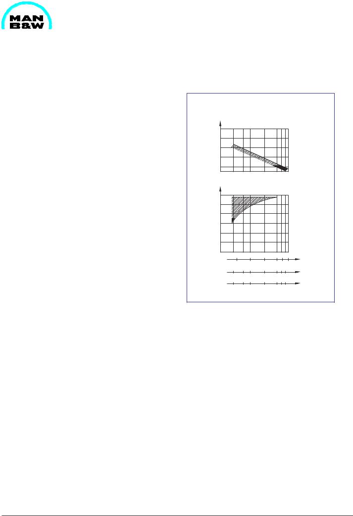
Nomogram for Determination of CCAI |
504.26 |
Page 1 (2) |
Edition 02 |
|
|
|
|
|
|
|
General |
08028-0D/H5250/94.08.12 |
Fig 1 Nomogram for determination of CCAI.
01.34 - ES1

504.26 |
Nomogram for Determination of CCAI |
Description |
Edition 02 |
Page 2 (2) |
|
|
|
|
|
|
|
General
Example: |
|
Viscosity: |
180 cSt at 50°C |
Density: |
990 kg/m³ at 15°C |
The combining straight line across density (990 kg/ m³) and viscosity (180 cSt) of a heavy fuel oil results in CCAI (859). From CCAI, conclusions may be derived with regard to the ignition qualities.
CCAI may be calculated with the aid of the following formula:
CCAI = D - 141 log (log (v + 0.85)) - 81
Ignition quality is an important fuel parameter. The reason why it does not appear in the international specificationsisthattherearenostandardizedtesting method is non-existent. Therefore, parameters such as the Calculated Carbon Aromaticity Index (CCAI) are resorted to as an aid which is derived from determinable fuel parameters. According to our experience, only a rough assessment of the ignition quality of the heavy fuel oil is possible with the help of this method.
However, the CCAI has become so well-known in widespread publications that, in spite of the reservations mentioned above. We were compelled to classify the respective MAN B&W Diesel A/S, Holeby engines according to CCAI-rating, too.
08028-0D/H5250/94.08.12
01.34 - ES1

Description |
Analysis Data |
504.27 |
|
Page 1 (4) |
Edition 02 |
||
|
|||
|
|
|
08028-0D/H5250/94.08.12
Comments on Analysis Data for Fuel Oils
Carbon Residue
The carbon residue of a fuel oil indicates its cokeforming tendency and can be used to determine the tendency to form deposits in the combustion chamber and gasways. The higher the carbon residue value, the higher the fouling tendency.
Some changes in the combustion process, requiring adjustment of the maximum pressure, may also be attributed to a high carbon residue content. The value is measured by standardized tests, such as the Conradson or Ramsbottom tests which give similar results.
The non-vaporized residue from the carbonizing test consists of carbonaceous material and inorganic impurities and is expressed as percentage weight of the fuel sample tested. Carbon residue and asphaltenes content generally move in parallel, both in relation to the carbon-to-hydrogen ratio, with increasing values for a higher ratio.
The carbon-to-hydrogen ratio and thus also the carbon residue depends on the source of the crude oil and the type of refinery processing used.
The effect of carbon residue is impossible to counteract by pre-treatment of the fuel oil, as centrifuging only influences solid inorganic contaminants and hard asphalts, which are only small amounts of the percentage weight called carbon residue.
Asphaltenes
Asphaltenes is defined as the part of a fuel oil sample which is insoluble in heptane. The content of asphalteness is expressed as percentage weight of the fuel oil sample tested.
Asphaltenes, which is aromatic, slow-burning, semisolid hydrocarbon compounds dispersed in the fuel oil, has a similar effect on the combustion process to the carbon residue, the main impact being fouling of gasways. The stability of the fuel oil is related to the asphaltenes content.
General
Asphaltenes also influences the lubricating properties of the fuel oil and, in extreme cases, high asphalteness content may lead to fuel injection pump sticking.
Fuel oils with a high asphalteness content will have a tendency to form sludge, especially if the water content is also high. The asphaltenes content of a fuel oil is influenced by pre-treatment. The heaviest semi-solid asphaltenes, and asphaltenes bound to water as sludge, can be separated by centrifuging.
Diesel Index
Diesel index is a calculated value to determine the ignition quality of a fuel oil. The ignition quality is related to the hydrocarbon composition, paraffin being of high quality, n-heptanes of moderate quality and aromatics of low quality.
With certain exceptions the properties of the aniline point and the specific gravity reflect the hydrocarbon composition of a fuel oil, and are therefore used in the following simple formula as an expression of ignition quality:
Diesel index = (aniline point °F x API gravity) x 0.01.
The aniline point is the lowest temperature at which equal volumes of the fuel and aniline become just miscible. The test relies on the fact that aromatic hydrocarbons mix completely with aniline at comparatively low temperatures, whereas paraffins require considerably higher temperatures before they are completely miscible.
A high aniline point thus indicates a highly paraffinic fuel, and consequently a fuel oil of good ignition quality. Similarly, a high API gravity number denotes a low specific gravity and high paraffinicity, and again a good ignition quality.
The diesel index provides a reasonable idea of the ignition quality, but generally gives figures slightly above the cetane number.
Fuel oils with poor ignition quality and a low diesel index might in particular cause problems in starting diesel engines and running at low load.
02.16 - ES0 - G

504.27 |
Analysis Data |
Description |
|
Edition 02 |
Page 2 (4) |
||
|
|||
|
|
|
General
In addition to starting difficulties, a prolonged ignition delay may give rise to alternations in the maximum pressure, leading to increased mechanical or thermal load.
Furthermore, fuel oils with poor ignition quality may cause retarded combustion and subsequent fouling of gasways.
Sulphur
Sulphur is present in fuel oil, mainly as organic compounds, the amount present being expressed as percentage weight of an oil sample tested. If free sulphur is present it may cause corrosion in the fuel system. The main problem caused by sulphur is low temperature corrosion. During combustion, sulphur oxides are produced in the form of gases. Since humidity is also present sulphur and sulphuric acid may be formed on components in the combustion chamber and in the gasways, where the temperature is below that of the dew point for sulphuric acid.
The detrimental effect of sulphur in fuel oil is counteracted by maintaining an adequate temperature of the combustion chamber components and by using alkaline lubricating oil to neutralize the sulphuric acid produced during combustion.
Vanadium and Sodium
Vanadium and sodium are constituents of the ash content. The amounts of these are measured by analyzing the residue from the combustion test used for determination of the ash content. The amount of vanadium and sodium present is expressed in ppm, parts per million, by weight in relation to the fuel oil sample being tested for ash content. Vanadium derives from the crude oil itself and, being oil soluble, cannot be removed from the fuel oil by conventional pre-treatment. Sodium derives from the crude oil, and also from contamination with salt water during storage and transport of the fuel oil. Sodium is watersoluble and, regardless of derivation, tends to combine with the water present in the fuel oil.
Owing to its water solubility, it is possible to remove or reduce the amount of sodium present in the fuel oil. During combustion, corrosive ash is formed from vanadium and sodium.
Especially if the weight ratio of sodium to vanadium exceeds 1:3, ash with a very low melting point and stiction temperature is formed, giving rise to high temperature corrosion of exhaust valves and deposit formation in turbochargers.
It is possible to reduce the tendency for formation of detrimental vanadium-sodium ash by effective centrifuging, which will remove sodium salts together with water. If a very low content of sodium is ensured, a relatively high vanadium content might be acceptable.
Water
The water content of fuel oil is measured by a standardized distillation test and is expressed as percentage volume of the sample tested. Water in the fuel oil may lead to several detrimental effects on the fuel oil system, and corrosion and cavitation of fuel injection pumps and fuel valves, and cause fouling of exhaust systems and turbochargers.
Due to its content of sodium, salt water in combination with vanadium contributes to the formation of low-melting corrosive ash, which attacks exhaust valves and turbochargers. When it disturbs the fuel atomization, water will lead to poor combustion, resulting in higher heat load on the combustion chamber components.
It is possible to reduce the water content of a fuel oil primarily by centrifuging, and this should be done to the widest possible extent in order to avoid the detrimental effects of water in the fuel oil.
Ash
Ash content is a measure of the non-combustible material present in the fuel oil. The ash content is determined by a combustion test and it is expressed as a percentage weight residue from complete combustion of the oil sample tested.
Ash-forming materials are present in the fuel oil as natural components of crude oil and due to external contamination of the fuel oil.
08028-0D/H5250/94.08.12
02.16 - ES0 - G

Description |
Analysis Data |
504.27 |
|
Page 3 (4) |
Edition 02 |
||
|
|||
|
|
|
General
08028-0D/H5250/94.08.12
Ash-forming materials exist both as solid contaminants and in soluble compounds. The solid contaminants may lead to abrasive wear in the fuel injection system. Ash formed during combustion may lead to abrasive as well as corrosive wear of combustion chamber components and give rise to formation of detrimental deposits. It is therefore essential, to the greatest possible extent, to reduce the amount of ash-forming materials by centrifuging.
Solid contaminants such as sand, rust, certain metal oxides and catalyst fines can be removed by centrifuging, and the same goes for water-soluble salts such as sodium.
Some of the components included in the ash content have been found to be particularly harmful and are therefore stated individually in the analysis data.
Silicium and Aluminium Oxides
Residual fuels produced by refineries using fluid catalytic cracking may be contaminated by catalyst particles in the form of silicium and aluminium oxides. Any catalyst particles are shown by the ash content value. Separate values for silicium oxide content and aluminium oxide content are measured by analyzing the ash content.
The amount of silicium and aluminium oxides is expressed in ppm in relation to the weight of the original fuel oil sample being tested for ash content.
As catalyst particles are very hard and abrasive, they can cause extreme mechanical wear of the fuel injection system, cylinder liners and piston rings.
Catalyst particles, being solid and insoluble, can be removed from the fuel oil. The guidelines for dimensioning the centrifuge size are based on the fact that approx. 1/3 of the catalyst particles in terms of weight is removed.
Viscosity
Basically viscosity is a measure of the internal friction or resistance of a liquid to flow.
Viscosity of Marine Gas Oil (MGO) and Marine Diesel Oil (MDO) are expressed in centistokes (cSt) at 40° C.
Viscosity is an important parameter in connection with pumping, pre-treatment and injection of fuel oil, since the possibility and efficiencyofthese processes to a large extent depend on adequate viscosity.
Adjustmentofviscositytoadequatevaluesispossible by takingadvantageof theinterdependence between the temperature and viscosity index of the fuel oil.
The nominal viscosity of a fuel oil is the factor determining the preheating temperatures necessary to obtain adequate viscosity for pumping, centrifuging and injection of the fuel oil, and thus also the factor determining the capacity of the preheating equipment in the fuel oil system.
Density
Density is defined as the mass of a unit volume and is expressed in g/cm³ at a temperature of 15°C (59°F).
Specific gravity is the ratio of the mass of a given volume of liquid at 60°F (15.6°C) and the mass of an equal volume of water at the same temperature. For a given liquid, the specific gravity will generally give the same numerical value as the density.
API gravity is an arbitrary scale calibrated in degrees and related to specific gravity by the following formula:
° API gravity = |
141.5 |
+ 131.5 |
|
specific gravity/50°F |
|||
|
|
As the formula indicates, the API gravity is in inverse proportion to density and specific gravity.
Density is an important parameter in the centrifuging process, where separating water and water-dis- solved impurities from the fuel oil is based on the difference in densities. If the density of the fuel oil approaches that of water, centrifuging thus becomes less effective, necessitating a reduced flow rate and therefore increased centrifuge capacity.
02.16 - ES0 - G

504.27 |
Analysis Data |
Description |
|
Edition 02 |
Page 4 (4) |
||
|
|||
|
|
|
General
The water separation ability of fuel oil is increased by preheating the fuel oil prior to centrifuging since the densities of fuel oil and water change with the temperature at different rates, thus making it possible to optimize density differences.
To some extent the quality of a fuel oil can be judged by the density, since this is directly proportional to the carbon-to-hydrogen ratio, which again is in direct proportion to aromativity, carbon residue and asphaltene content, but in reverse ratio to calorific value.
Analysis Data for Fuel Oils
|
Carbon Residue |
% weight |
|
|
Asphaltenes |
% weight |
|
|
Diesel Index |
|
|
Engine- |
FIA |
|
|
Relevant |
Ash |
% weight |
|
Properties |
Sulphur |
% weight |
|
|
Water |
% volume |
|
|
Vanadium |
ppm |
|
|
Sodium |
ppm |
|
|
Silicium Oxide |
ppm |
|
|
Aluminium Oxide |
ppm |
|
|
|
|
|
|
Viscosity |
cSt/50°C |
|
Installation- |
Density |
g/ml |
|
Relevant |
Flash Point |
°C |
|
Properties |
Pour Point |
°C |
|
|
|
|
|
Table 2 Analysis data for fuels.
Pour Point
The pour point is the lowest temperature at which an oil will flow or can be poured. The pour point is measured under specific test conditions. Fuel oil must be stored, handled and pumped at temperatures above the pour point to avoid wax crystallization, which may result in precipitation in storage tanks, blocking of filters and pipe lines and prevention of pumpability. Normally, the pour point of residual fuel oil does not create any problems, since the temperature needed to reduce the viscosity to pumpable levels will be adequately in excess of the pour point.
Flash Point
The flash point of an oil is defined as the temperature at which it gives off sufficient vapour to create an inflammable mixture with air. This mixture will ignite or flash under the influence of an open flame, but will not support combustion itself. The flash point of fuel oil is normally tested by the Pensky-Martens closedup method.
In order to provide a sufficient margin of safety from fire risk during storage, handling and transportation, fuel oils for shipboard use must meet the classification societies' requirements of flash point, limited to a minimum of 60°C (140°F).
08028-0D/H5250/94.08.12
02.16ES0 - G

Description |
Fuel Oil Cleaning |
504.30 |
|
Page 1 (2) |
Edition 01 |
||
|
|||
|
|
|
08028-0D/H5250/94.08.12
Purification Recommendations
Fuel oils are always contaminated and should therefore be cleaned thoroughly of solid as well as liquid contaminants before use. The solid contaminants in the fuel are mainly rust, sand, dust and refinerycatalysts.Liquidcontaminantsaremainlywater, i.e. either fresh water or sea water.
The impurities can cause damage to fuel injection pumps and fuel valves, result in increased cylinder liner wear and cause the exhaust valve seats to deteriorate. Increased fouling of gasways and turbocharger blends may also result from the use of inadequately cleaned fuel oils.
Effective cleaning can only be ensured by means of a centrifuge. We recommend that the capacity of the centrifuges installed be at least according to the centrifuge maker's recommendations. To obtain optimum cleaning it is of the utmost importance to operate the centrifuge with as low a viscosity of the fuel oil as possible and to allow the fuel oil to remain in the centrifuge bowl for as long as possible.
|
Cleaning of HFO by Centrifuging |
|||
|
|
|
|
|
Operating |
|
Single centrifuge as purifier. |
||
|
Two centrifuges in parallel. |
|||
options |
|
|||
|
|
Two centrifuges in series. |
|
|
|
|
|
|
|
|
Optimum Operating Configurations |
|||
|
|
|
|
|
|
|
Water content |
|
Parallel operation |
Normal |
|
below 1 % |
|
Purifier / Purifier |
|
|
|
or |
|
conditions |
|
|
|
|
|
Density at 15°C |
|
Series operation |
|
|
|
|
||
|
|
below 0.991 |
|
Purifier + Clarifier |
|
|
|
|
|
|
|
Water content |
|
|
|
|
below 1 % |
|
Parallel operation |
Extreme |
|
Density at 15°C |
|
Purifier / Purifier |
conditions |
|
below 0.991 |
|
|
|
|
|
|
|
|
|
|
|
|
|
|
High content |
|
Series operation |
|
|
of catalyst fines |
|
Purifier + Clarifier |
|
|
|
|
|
Table 1. Cleaning of HFO.
General
Especially for fuels above 180 cST/50°C (1500 sec. RW/100°F) the highest possible temperature of 98°C (208°F) should be maintained in the centrifuge oil preheater.
The fuel is kept in the centrifuge for as long as possible by adjusting the flow rate through the centrifuge so that it corresponds to the amount of fuel required by the engine without excessive recirculating. Consequently, the centrifuge should operate for 24 hours a day except during necessary cleaning.
Taking today's fuel qualities into consideration the need to clean centrifuges ("shooting frequency") should not be underestimated. Correct choice and adjustmentoftheregulatingscrewsand/orthegravity discs are of special importance for efficient water removal. The centrifuge manual states the disc or screw adjustment which should be chosen on the basis of the specific gravity of the fuel.
Normal practice is to have at least two centrifuges available for fuel cleaning. Results from experimental work on centrifuges, treating today's qualities of residual fuel, have shown that the best cleaning effect, especially as regards removal of catalyst fines, is achieved when the centrifuges are operated in series, in purifier/clarifier mode.
Therefore series operation of centrifuges to ensure maximum safety is a fully accepted alternative to the previouslyrecommendedparalleloperation,provided the operating capacity of each individual centrifuge can handle the total amount of fuel required by the engine,withoutexceedingtheflowraterecommended by the centrifuge maker for the operating mode in question.
If the centrifuge capacity installed is on the low side, corresponding to the specific viscosity of the fuel oil used, and if more than one centrifuge is available, parallel operation may be considered in order to obtain an even lower flow rate. However, in view of the above results and recommendations serious consideration should be given to installing new equipment in accordance with today's fuel qualities and flow recommendations.
97.40 - ES0
504.30 |
Fuel Oil Cleaning |
Description |
|
Edition 01 |
Page 2 (2) |
||
|
|||
|
|
|
General
To determine centrifuging capacity we generally advise to follow the recommendations of the centrifuge maker, but the curves in fig. 1, can be used as a guideline.
A homogenizer may be installed in the fuel oil system as a supplement to the centrifuges in order to homogenize possible water and sludge still present in the fuel after centrifuging.
Flow Rate
Related to Rated Capacity of Centrifuge
% |
100 |
80 |
60 |
40 |
20 |
|
Separation |
Temperature |
|
|
|
||||
°F |
°C |
|
|
|
|
|
|
|
|
212 |
100 |
|
|
|
|
|
|
|
|
194 |
90 |
|
|
|
|
|
|
|
|
176 |
80 |
|
|
|
|
|
|
|
|
158 |
70 |
|
|
|
|
|
|
|
|
140 |
60 |
|
|
|
|
|
|
|
|
122 |
50 |
|
|
|
|
|
|
|
|
104 |
40 |
|
|
|
|
100 |
|
|
|
|
|
|
|
|
|
|
|
||
|
|
15 |
|
25 |
45 |
75 |
130 |
cSt/80°C |
|
Log |
scales |
30 |
60 80 |
180 |
380 600 |
cST/50°C |
|||
|
|
200 400 600 1500 3500 6000 sec. |
RI/100°F |
||||||
Fig. 1 Flow rate through centrifuge related to nominal capacity of centrifuge.
08028-0D/H5250/94.08.12
97.40 - ES0

Description |
Freshwater System Treatment |
504.40 |
|
Page 1 (5) |
Edition 02 |
||
|
|||
|
|
||
|
|
|
|
|
|
General |
08028-0D/H5250/94.08.12
Protection against Corrosion in Freshwater Cooling System
The engine fresh water must be carefully treated, maintained and monitored so as to avoid corrosion or the formation of deposits which can result in insufficient heat transfer, it is necessary to treat the cooling water. MAN B&W recommend that this treatment is carried out according to the following procedure:
–Clean the cooling water system.
–Fill up with deionized or distilled cooling water (for example from the freshwater generator) with corrosion inhibitor added.
–Carry out regular checks of the cooling water system and the condition of the cooling water.
Observance of these precautions, and correct venting of the system, will reduce service difficulties caused by the cooling water to a minimum.
Cleaning of the Cooling Water System
Before starting the inhibition process, any existing deposits of lime or rust, or any oil sludge, should be removed in order to improve the heat transfer and to ensure uniform protection of the surface by means of the inhibitor.
The cleaning should comprise degreasing to remove oil sludge, and descaling with acid afterwards to remove rust and lime deposits.
Ready-mixed cleaning agents, specially made for cleaning the cooling water system, can be obtained from companies specializing in cooling water treatment. These companies offer assistance and control of the treatment in all major ports. A number of these companies are mentioned on the enclosed list. We point out that the directions given by them should be closely followed. It is of particular importance to flush the system completely after cleaning.
Cleaning agents emulsified in water as well as slightly alkaline cleaning agents can be used for the degreasing process, whereas ready-mixed cleaning agents which involve the risk of fire must obviously not be used. For descaling with acid, especially products based on amino-sulphonic acid, citric acid, and tartaric acid are recommendable, as these acids are usually obtainable as solid substances, easily soluble in water, and do not emit poisonous vapours.
The cleaning agents should not be directly admixed, but should be dissolved in water and then added to the cooling water system.
Normally, cleaning can be executed without any dismantling of the engine. We point out that the water should be circulated in the engine to achieve the best possible result.
As cleaning can cause leaks to become apparent in poorly assembled joints or partly defective gaskets, inspection should be carried out during the cleaning process. The acid content of the system oil should also be checked immediately after cleaning, and 24 hours afterwards.
Cooling Water - Inhibitors
The filling-up with cooling water and the admixture of the inhibitor is to be carried out directly after the cleaning in order to prevent formation of rust on the cleaned surfaces.
Raw Water
The formation of lime stone on cylinder liners and in cylinder heads may reduce the heat transfer, which will result in unacceptably high temperatures in the material.
Therefore, it is recommended that deionized or distilled water (for example from the freshwater generator) is used as cooling water. However, on account of its lack of hardness, this water will be relatively corrosive, and a corrosion inhibitor should therefore always be added.
00.11ES1

504.40 |
Freshwater System Treatment |
Description |
|
Edition 02 |
Page 2 (5) |
||
|
|||
|
|
||
|
|
|
|
General |
|
|
If deionized or distilled water cannot be obtained, normal drinking water can be used in exceptional cases. If so, the total hardness of the water must not exceed 9° dH (German hardness degrees). The chloride, chlorine, sulphate, and silicate contents are also to be checked. These contents should not exceed the following values:
Chloride |
50 ppm |
(50 mg/litre) |
Chlorine |
10 ppm |
(10 mg/litre) |
Sulphate |
100 ppm |
(100 mg/litre) |
Silicate |
150 ppm |
(150 mg/litre) |
There should be no sulphide and ammonia content. Rain water must not be used, as it may be heavily contaminated.
It should be noted that softening of water does not reduce its sulphate and chloride contents.
Corrosion Inhibitors
To protect freshwater cooling systems in marine diesel engines against corrosion, various types of inhibitors are available.
Generally, only nitrite-borate based inhibitors are recommended.
A number of the products marketed by major companies are specified on the enclosed list, together with the necessary dosages and admixing procedures. We recommend that these directions are strictly observed.
Treatment of the cooling water with inhibting oils is not recommended, as such treatment involves the risk of oil adhering to the heat transmitting surfaces.
Chromate inhibitors must not be used in plants connected to a freshwater generator.
Evaporated cooling water is to be replaced with noninhibited water, whereas a loss of water through leakage must be replaced with inhibited water.
When overhauling individual cylinders, a new dosage of inhibitor must, if necessary, be added immediately after completing the job.
Checking of the Cooling Water System and the Cooling Water during Service
If the cooling water is contaminated during service, sludge or deposits may form. The condition of the cooling water system should therefore be regularly checked, especially if deionized or distilled water is not used. If deposits are found in the cooling spaces, these spaces or, if necessary, the entire system should be cleaned.
According to experience, a zinc galvanized coating in the freshwater cooling system is often very susceptible to corrosion, which results in heavy formation of sludge, even if the cooling water is correctly inhibited. The initial descaling with acid will, to a great extent, remove the galvanized coating. Generally, therefore, we advise against the use of galvanized piping in the freshwater cooling system.
The quality of the cooling water is to be checked regularly, if possible once a week. Basically the inhibitor concentration, the pH value and the chloride concentration should be in accordance with limits stated by inhibitor manufacturer. For this purpose the inhibitor manifactures normally supply simple test kits.
As a general guidance values the pH value should be 7-10 measured at 20° C and the chloride concentration should not exceed 50 ppm (50 mg/litre).
The water sample for these tests is to be taken from the circulating system, and not from the expansion tank or the pipe leading to it.
The concentration of inhibitor must under no circumstances be allowed to fall below that recommended by the producer, as this would increase the risk of corrosion.
A clear record of all measuring results should be kept, so that the actual condition and trend of the system may be currently ascertained and evaluated.
A sudden or gradual increase in the chloride content of the cooling water may be indicative of salt water leakages. Such leakages are to be traced and repaired at the first opportunity.
08028-0D/H5250/94.08.12
00.11ES1