

7 семестр (Бормотов А) / 1man_bw_l23_30_chn_23_30_instruktsiya_po_ekspluatatsii_1 / MAN-BW L23-30 H Vol-1 (Instruction)+
.pdfDescription |
|
Code Identification for Instruments |
500.20 |
|
Page 1 (2) |
|
Edition 03 |
||
|
|
|
|
|
|
|
|
|
General |
Explanation of Symbols |
|
|||
|
|
TI |
Measuring device |
|
|
|
Local reading |
|
|
40 |
|
|||
|
|
|||
|
|
|
Temperature Indicator |
|
|
|
|
No. 40 * |
|
|
|
PI |
Measuring device |
|
|
|
Sensor mounted on engine/unit |
|
|
|
22 |
Reading/identification mounted in a panel on the engine/unit |
|
|
Pressure Indicator
No. 22 *
|
Measuring device |
TAH |
Sensor mounted on engine/unit |
12Reading/identification outside the engine/unit
Temperature Alarm High No. 12 *
PT |
Measureing device |
Sensor mounted on engine/unit |
22Reading/identification in a panel on the engine/unit and reading/indication outside the engine/unit
Pressure Transmitting No. 22 *
*Refer to standard location and text for instruments on the following pages.
|
Specification of letter code for measuring devices |
|||
|
|
|
|
|
|
|
1st letter |
Following letters |
|
|
|
|
|
|
|
F |
Flow |
A |
Alarm |
|
L |
Level |
D |
Differential |
0D/H5250/94.08.12- |
P |
Pressure |
E |
Element |
U |
Voltage |
L |
Low |
|
|
S |
Speed, System |
H |
High |
|
T |
Temperature |
I |
Indicating |
08028 |
V |
Viscosity |
S |
Switching, Stop |
|
||||
|
X |
Sound |
T |
Transmitting |
|
Z |
Position |
X |
Failure |
|
|
|
V |
Valve, Atuator |
|
|
|
|
|
04.36 - ES1

500.20 |
Code Identification for Instruments |
Description |
Edition 03 |
Page 2 (2) |
|
|
|
|
General
Standard Text for Instruments
Diesel Engine/Alternator
LT Water System |
|
|
|
|
|
01 |
inlet to air cooler |
04 |
inlet to alternator |
07 |
inlet to lub. oil cooler |
02 |
outlet from air cooler |
05 |
outlet from alternator |
08 |
inlet to fresh water cooler (SW) |
03 |
outlet from lub. oil cooler |
06 |
outlet from fresh water cooler (SW) |
09 |
|
HT Water System |
|
|
|
|
|
10 |
inlet to engine |
14 |
inlet to HT air cooler |
17 |
outlet from fresh water cooler |
10A FW inlet to engine |
14A |
FW inlet to air cooler |
18 |
inlet to fresh water cooler |
|
11 |
outlet from each cylinder |
14B |
FW outlet from air cooler |
19 |
preheater |
12 |
outlet from engine |
15 |
outlet from HT system |
19A |
inlet to prechamber |
13 |
inlet to HT pump |
16 |
outlet from turbocharger |
19B |
outlet from prechamber |
Lubricating Oil System |
|
|
|
|
|
20 |
inlet to cooler |
24 |
sealing oil - inlet engine |
28 |
level in base frame |
21 |
outlet from cooler / inlet to filter |
25 |
prelubricating |
29 |
main bearings |
22 |
outlet from filter / inlet to engine |
26 |
inlet rocker arms and roller guides |
|
|
23 |
inlet to turbocharger |
27 |
intermediate bearing / alternator bearing |
|
|
Charging Air System |
|
|
|
|
|
30 |
inlet to cooler |
34 |
charge air conditioning |
38 |
|
31 |
outlet from cooler |
35 |
surplus air inlet |
39 |
|
32 |
jet assist system |
36 |
inlet to turbocharger |
|
|
33 |
outlet from TC filter / inlet to TC compr. |
37 |
charge air from mixer |
|
|
Fuel Oil System |
|
|
|
|
|
40 |
inlet to engine |
44 |
outlet from sealing oil pump |
48 |
|
41 |
outlet from engine |
45 |
fuel-rack position |
49 |
|
42 |
leakage |
46 |
inlet to prechamber |
|
|
43 |
inlet to filter |
47 |
|
|
|
Nozzle Cooling System |
|
|
|
|
|
50 |
inlet to fuel valves |
54 |
|
58 |
oil splash |
51 |
outlet from fuel valves |
55 |
valve timing |
59 |
alternator load |
52 |
|
56 |
injection timing |
|
|
53 |
|
57 |
|
|
|
Exhaust Gas System |
|
|
|
|
|
60 |
outlet from cylinder |
64 |
|
68 |
|
61 |
outlet from turbocharger |
65 |
|
69 |
|
62 |
inlet to turbocharger |
66 |
|
|
|
63 |
compustion chamber |
67 |
|
|
|
Compressed Air System |
|
|
|
|
|
70 |
inlet to engine |
74 |
inlet to reduction valve |
78 |
inlet to sealing oil system |
71 |
inlet to stop cylinder |
75 |
microswitch for turning gear |
79 |
|
72 |
inlet to balance arm unit |
76 |
inlet to turning gear |
|
|
73 |
control air |
77 |
waste gate pressure |
|
|
Load Speed |
|
|
|
|
|
80 |
overspeed air |
84 |
engine stop |
88 |
index - fuel injection pump |
81 |
overspeed |
85 |
microswitch for overload |
89 |
turbocharger speed |
82 |
emergency stop |
86 |
shutdown |
90 |
engine speed |
83 |
engine start |
87 |
ready to start |
|
|
Miscellaneous |
|
|
|
|
|
91 |
natural gas - inlet to engine |
94 |
cylinder lubricating |
97 |
remote |
92 |
oil mist detector |
95 |
voltage |
98 |
alternator winding |
93 |
knocking sensor |
96 |
switch for operating location |
99 |
common alarm |
08028-0D/H5250/94.08.12
04.36 - ES1
Description |
Introduction to Planned Maintenance Programme |
500.24 |
Page 1 (2) |
Edition 03 |
|
|
|
|
|
|
|
General
The overhaul intervals are based on operation on a specified fuel oil quality at normal service output, which means 70-100% of MCR.
In the long run it is not possible to achieve safe and optimum economical running without an effective maintenance system.
The structure and amount of information in the maintenance programme mean that it can be integrated in the entire ship's/power station's maintenance system or it can be used separately.
The core of the maintenance system is the key diagram, see pages 500.25 and 500.26, indicating the inspection intervals for the components/systems, so that the crew can make the necessary overhauls based on the engines' condition and/or the time criteria.
General
The front page indicates the following:
1) |
Safety regulations, which MUST be carried out |
|
before the maintenance work can start. |
2) |
A brief description of the work. |
3) |
Reference to any work which must be carried |
|
out before the maintenance work can start. |
4) |
Related procedures - indicates other works, |
|
depending on the present work - or works |
|
which it would be expedient to carry out. |
5) |
Indicates x number of men in x number of |
|
hours to accomplish the work. |
The stated consumption of hours is only intended as a guide.
08028-0D/H5250/94.08.12
The maintenance system is divided into 2 main groups:
a. Major overhaul / inspection (page 500.25): These works are to be carried out during major overhauls and inspections of the engine.
b. Duty during operation (page 500.26): indicated the works to be carried out by the personnel during the daily operation of the engine.
The stated recommended intervals are only for guidance as different service conditions, the quality of the fuel oil and the lubricating oil, treatment of the cooling water, etc., will decisively influence the actual service results and thus the intervals between necessary overhauls.
Experience with the specific plant/personnel should be used to adjust the time between overhauls. It should also be used to adjust the timetable stated for guidance in the working cards.
Working Cards
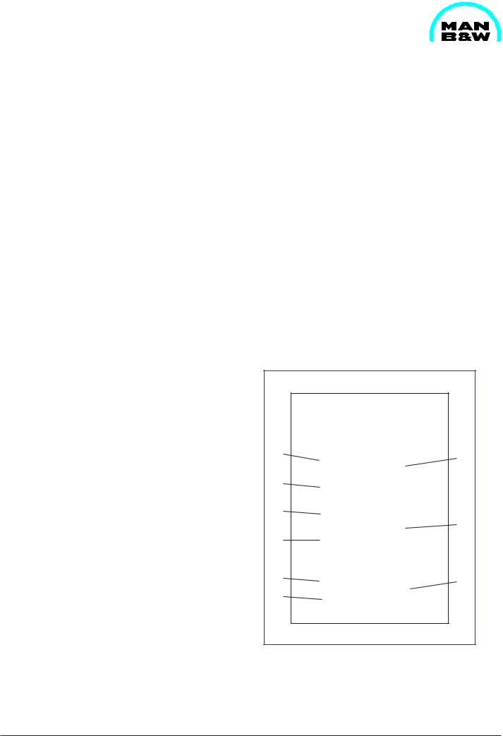
Each of the working cards can be divided into two: a front page and one or several pages describing and illustrating the maintenance work.
1 |
7 |
|
|
2 |
|
3 |
|
|
8 |
4 |
|
5 |
9 |
|
|
6 |
|
Fig. 1 Instruction guide for working cards.
98.19 - ES0

500.24 |
|
Introduction to Planned Maintenance Programme |
Description |
||||
Edition 03 |
|
Page 2 (2) |
|||||
|
|
|
|
|
|||
|
|
|
|
|
|
||
General |
|
|
|
|
|||
Experience with the specific station/personnel may |
8) |
Various requisite hand tools. |
|
||||
lead to updating. |
|
9) |
Indicates the components/parts which it is |
||||
6) |
Refers to data required to carry out the work. |
||||||
|
advisible to replace during the maintenance |
||||||
7) |
Special tools which must be used. Please note |
|
work. Please note that this is a condition for the |
||||
|
intervals stated. |
|
|||||
|
that not all tools are standard equipment. |
|
|
|
|||
08028-0D/H5250/94.08.12
98.19 - ES0

|
Description |
|
Planned Maintenance Programme |
|
|
500.25 |
||||||||||||||
|
Page 1 (4) |
|
|
|
Edition 01H |
|||||||||||||||
|
|
|
|
|
|
|
|
|
|
|
|
|
|
|
|
|
|
|
||
|
|
|
|
|
|
|
|
|
|
|
|
|
|
|
|
|
|
|
|
|
|
|
|
|
|
|
|
|
|
|
|
|
|
|
|
|
|
|
|
L23/30H |
|
|
|
|
|
|
|
|
|
|
|
|
|
|
|
|
|
|
|
|
720/750 RPM |
|
|
|
|
|
|
|
|
|
|
|
|
|
|
|
|
|
|
|
|
|
|
|
|
|
|
|
|
new/Check partsoverhauled hoursafter |
Time Between Overhaul |
|
|
|
||||||||||
|
|
Description |
n = |
Check the condition |
50 200 2000 8000 16000 32000 Daily Weekly Monthly month3rd |
Observations |
|
Working |
|
|||||||||||
|
|
|
|
|
|
|
|
|
|
|
|
|
|
|
|
|||||
|
|
|
|
|
|
|
|
|
|
|
|
|
|
|
Card |
|
||||
|
|
|
|
l = |
Overhaul to be carried out |
|
|
|
|
|
|
|
|
|
|
|
|
|
|
|
|
|
|
|
|
|
|
|
|
|
|
|
|
|
|
|
|
|
|
No |
|
|
|
|
|
|
|
|
|
|
|
|
|
|
|
|
|
|
|
|
|
|
|
|
Operating of Engine: |
|
|
|
|
|
|
|
|
|
|
|
|
|
|
|
|
|
|
|
|
Readings of data for engine and alternator with refe- |
|
|
|
|
|
|
|
|
|
|
|
|
|
502-01.00 |
|
|||
|
|
rence to "Engine Performance Data", section 502.01 ...... |
|
|
|
|
|
|
|
|
n |
|
|
|
|
|
||||
|
|
|
|
|
|
|
|
|
|
|
|
|
|
|
|
|
|
|
|
|
|
|
Cylinder Head: |
|
|
|
|
|
|
|
|
|
|
|
|
|
|
|
|
|
|
|
|
Inlet and exhaust valve - overhaul and regrinding of |
|
|
|
|
|
|
|
|
|
|
|
|
|
505-01.10 |
|
|||
|
|
spindle and valve seat |
.................................................... |
|
|
|
|
|
|
l |
|
|
|
|
|
|
|
|
||
|
|
Inspection of inlet, exhaust valves and valve guide ........ |
|
|
|
|
|
n |
|
|
|
|
|
|
|
505-01.05 |
|
|||
|
|
Check of valve rotators' rotation during engine rotation.... |
|
|
|
n |
|
|
|
|
|
|
|
|
|
505-01.05 |
|
|||
|
|
Sleeve for fuel injector .................................................... |
|
|
|
|
|
|
|
n |
|
|
|
|
|
|
|
505-01.30 |
|
|
|
|
Safety valve - overhaul and adjustment of opening |
|
|
|
|
|
|
|
|
|
|
|
|
|
505-01.25 |
|
|||
|
|
pressure .......................................................................... |
|
|
|
|
|
|
|
n |
|
|
|
|
|
|
|
|
||
|
|
Indicator valve ................................................................ |
|
|
|
|
|
|
|
n |
|
|
|
|
|
n |
505-01.26 |
|
||
|
|
...............Cylinder head cooling water space - inspection |
|
|
|
|
|
n |
|
|
|
|
|
|
|
505-01.45 |
|
|||
|
|
Cylinder head nut - retightening ....................................... |
|
200 |
|
|
|
|
|
|
|
|
|
|
|
|
505-01.40 |
|
||
|
|
|
|
|
|
|
|
|
|
|
|
|
|
|
|
|
|
|||
|
|
Piston, Connecting Rod and Cylinder Liner: |
|
|
|
|
|
|
|
|
|
|
|
|
|
|
|
|||
|
|
Inspection of piston......................................................... |
|
|
|
|
|
|
|
n |
|
|
|
|
|
|
|
506-01.10 |
|
|
|
|
Piston ring and scraper ring ............................................ |
|
|
|
|
|
|
l |
|
|
|
|
|
|
|
506-01.10 |
|
||
|
|
Piston pin and bush for connecting rod - check of |
|
|
|
|
|
|
|
|
|
|
|
|
|
506-01.15 |
|
|||
|
|
clearance ........................................................................ |
|
|
|
|
|
|
|
n |
|
|
|
|
|
|
|
|
||
|
|
....................Connecting rod - measuring of big-end bore |
|
|
|
|
|
n |
|
|
|
|
|
|
|
506-01.15 |
|
|||
|
|
................................Inspection of big-end bearing shells |
|
|
|
|
|
n |
|
|
|
|
|
|
|
506-01.16 |
|
|||
0D/H5250/94.08.12- |
|
Connecting rod - retightening ........................................... |
|
200 |
|
|
|
n |
|
|
|
|
|
|
|
|
506-01.25 |
|
||
|
...............Cylinder liner - cleaning, honing and measuring |
|
|
|
|
|
l |
|
|
|
|
|
|
|
506-01.35 |
|
||||
|
Camshaft and Camshaft Drive: |
|
|
|
|
|
|
|
|
|
|
|
|
|
|
|
|
|||
|
|
Cylinder liner removed - check the water space and |
|
|
|
|
|
|
|
|
|
|
|
|
|
506-01.40 |
|
|||
|
|
wear ring in frame ........................................................... |
|
|
|
|
|
|
|
|
n |
|
|
|
|
|
|
|
||
08028 |
|
Camshaft - Inspection of gear wheels, bolts, connections |
200 |
|
|
|
|
|
|
|
|
|
|
|
|
507-01.00 |
|
|||
|
|
etc. ................................................................................. |
|
|
|
|
|
|
n |
|
|
|
|
|
|
|
|
|||
|
|
.....................Camshaft bearing - inspection of clearance |
|
|
|
|
|
n |
|
|
|
|
|
|
|
507-01.05 |
|
|||
|
|
....................Camshaft adjustment - check the condition |
|
|
|
|
|
n |
|
|
|
|
|
|
|
507-01.20 |
|
|||
|
|
..........................Lubrication of camshaft bearing - check |
|
|
|
|
|
n |
|
|
|
|
|
|
|
507-01.00 |
|
|||
|
|
|
|
|
|
|
|
|
|
|
|
|
|
|
|
|
|
|
|
|
96.02 - ES0U

500.25 |
Planned Maintenance Programme |
Description |
Edition 01H |
Page 2 (4) |
|
|
|
|
|
|
|
L23/30H
720/750 RPM
|
|
|
new/Check partsoverhauled hoursafter |
Time Between Overhaul |
|
||||||||||
Description |
n = |
Check the condition |
50 200 2000 8000 16000 32000 Daily Weekly Monthly month3rd |
Observations |
Working |
||||||||||
|
|
|
|
|
|
|
|
|
|
|
|
||||
|
|
|
|
|
|
|
|
|
|
|
|
Card |
|||
|
l = |
Overhaul to be carried out |
|
|
|
|
|
|
|
|
|
|
|
|
|
|
|
|
|
|
|
|
|
|
|
|
|
|
|
|
No |
|
|
|
|
|
|
|
|
|
|
|
|
|
|
||
Operating Gear for Inlet Valves, Exhaust Valves and |
|
|
|
|
|
|
|
|
|
|
|
|
|
||
Fuel Injection Pumps: |
|
|
|
|
|
|
|
|
|
|
|
|
|
|
|
Roller guide for valve gear ............................................... |
|
|
|
|
|
|
|
n |
|
|
|
|
|
|
508-01.00 |
Valve gear - valve bridge, spring, push rod, etc .............. |
|
|
|
|
|
n |
|
|
|
|
|
|
508-01.10 |
||
Roller guide for fuel injection pump |
.................................. |
|
|
|
|
|
n |
|
|
|
|
|
|
508-01.05 |
|
Roller guide housing ........................................................ |
|
|
|
|
|
|
|
n |
|
|
|
|
|
|
508-01.10 |
Inlet and exhaust valve - check and adjustment of valve |
|
|
|
|
|
|
|
|
|
|
|
|
508-01.10 |
||
clearance ........................................................................ |
|
|
|
|
|
n |
|
|
|
|
|
|
|
|
|
Lubricating of operating gear - check............................... |
|
|
|
|
|
n |
|
|
|
|
|
|
508-01.00 |
||
|
|
|
|
|
|
|
|
|
|
|
|
|
|
|
508-01.05 |
Control and Safety System, Automatics and |
|
|
|
|
|
|
|
|
|
|
|
|
|
||
Instruments: |
|
|
|
|
|
|
|
|
|
|
|
|
|
|
|
Safety, alarm and monitoring equipment ......................... |
|
|
|
|
|
|
|
|
|
|
n |
|
509-01.00 |
||
Lambda controller - adjustment ....................................... |
|
|
|
|
|
|
|
|
|
|
|
n |
|
509-10.00 |
|
Governor - check oil level, see governor instruction |
|
|
|
|
|
|
|
|
|
|
|
|
|
||
book, section 509 ........................................................... |
|
|
|
|
|
|
|
|
|
|
|
|
n |
|
|
|
|
|
|
|
|
|
|
|
|
|
|
|
|
|
|
Crankshaft and Main Bearing: |
|
|
|
|
|
|
|
|
|
|
|
|
|
|
|
Checking of main bearings alignment, (autolog) .............. |
|
|
|
|
n |
|
|
|
|
|
|
|
510-01.00 |
||
Inspection af main bearing .............................................. |
|
|
|
|
|
|
|
|
n |
|
|
|
|
|
510-01.05 |
Inspection of guide bearing ............................................. |
|
|
|
|
|
|
n |
|
|
|
|
|
|
|
510-01.10 |
Vibration damper - check the condition ........................... |
|
|
|
|
|
n |
|
|
|
|
|
|
510-04.00 |
||
Lubricating of gear wheel for lub. oil pump and cooling |
|
|
|
|
|
|
|
|
|
|
|
|
|
||
water pump etc. .............................................................. |
|
|
|
|
|
|
|
|
n |
|
|
|
|
|
|
Counterweight - retightening, see page 500.40 ................ |
200 |
|
|
|
n |
|
|
|
|
|
|
|
|
||
Mainand guide bearing cap - retightening ...................... |
200 |
|
|
|
n |
|
|
|
|
|
|
|
510-01.05 |
||
|
|
|
|
|
|
|
|
|
|
|
|
|
|
|
510-01.10 |
|
|
|
|
|
|
|
|
|
|
|
|
|
|
|
|
08028-0D/H5250/94.08.12
96.02 - ES0U

Description |
Planned Maintenance Programme |
500.25 |
Page 3 (4) |
Edition 01H |
|
|
|
|
|
|
|
08028-0D/H5250/94.08.12
|
|
|
|
|
|
|
|
|
|
|
|
|
|
|
L23/30H |
|
|
|
|
|
|
|
|
|
|
|
|
|
|
|
|
720/750 RPM |
|
|
|
|
|
|
|
|
|
|
|
|
|
|
|
|
|
|
|
|
|
new/Check partsoverhauled hoursafter |
Time Between Overhaul |
|
|
||||||||||
Description |
n = |
Check the condition |
50 200 2000 8000 16000 32000 Daily Weekly Monthly month3rd |
Observations |
Working |
|
||||||||||
|
|
|
|
|
|
|
|
|
|
|
|
|
||||
|
|
|
|
|
|
|
|
|
|
|
|
Card |
|
|||
|
l = |
Overhaul to be carried out |
|
|
|
|
|
|
|
|
|
|
|
|
|
|
|
|
|
|
|
|
|
|
|
|
|
|
|
|
|
No |
|
|
|
|
|
|
|
|
|
|
|
|
|
|
|
|
|
|
Engine Frame and Baseframe: |
|
|
|
|
|
|
|
|
|
|
|
|
|
|
|
|
Holdingdown bolts - retightening, see page 500.40 .......... |
200 |
|
|
|
n |
|
|
|
|
|
|
|
|
|
||
Bolts between engine frame and base frame - |
|
|
|
|
|
|
|
|
|
|
|
|
|
|
||
retightening, see page 500.40 ......................................... |
|
200 |
|
|
|
n |
|
|
|
|
|
|
|
|
|
|
For flexible mounted engines - check anti-vibration |
|
|
|
|
|
|
|
|
|
|
|
|
519-03.00 |
|
||
mountings ....................................................................... |
|
|
200 |
|
|
|
n |
|
|
|
|
|
|
|
|
|
Safety cover - function test ............................................. |
|
|
|
|
|
|
n |
|
|
|
|
|
|
|
511-01.00 |
|
|
|
|
|
|
|
|
|
|
|
|
|
|
|
|
|
|
Turbocharger System: |
|
|
|
|
|
|
|
|
|
|
|
|
|
|
|
|
Wet cleaning of turbine side ............................................ |
|
|
|
|
|
|
|
|
|
|
l |
|
|
|
512-15.00 |
|
Water washing of compressor side.................................. |
|
|
l |
|
|
|
|
|
|
|
|
|
|
512-05.00 |
|
|
Cleaning of air filter - compressor side (see turbo- |
|
|
|
|
|
|
|
|
|
|
|
|
|
|
||
charger instruction book) ................................................. |
|
|
|
|
|
|
|
|
|
|
|
|
|
|
|
|
Turbocharger complete - dismantling, cleaning, inspec- |
|
|
|
|
|
|
|
|
|
|
|
|
|
|
||
tion etc. (see turbocharger instruction book) .................... |
|
|
|
|
|
|
|
|
|
|
|
|
512-01.00 |
|
||
Charging air cooler - cleaning and inspection................... |
|
|
|
|
|
|
|
|
|
|
|
n |
|
|||
Charging air cooler housing - draining .............................. |
|
|
|
|
|
|
|
|
|
|
|
l |
|
|
||
Exhaust pipe - compensator |
........................................... |
|
|
|
|
|
|
|
|
|
|
|
|
n |
|
|
|
|
|
|
|
|
|
|
|
|
|
|
|
|
|
|
|
Compressed Air System: |
|
|
|
|
|
|
|
|
|
|
|
|
|
|
|
|
Air starter motor - dismantling and inspection ................. |
|
|
|
|
|
|
|
|
|
|
|
n |
513-01.30 |
|
||
Function test - main starting valve, starting valve, main |
|
|
|
|
|
|
|
|
|
|
|
|
513-01.40 |
|
||
valves and emergency start valve ................................... |
|
|
|
|
|
|
|
|
|
|
|
n |
|
|
||
Dirt separator - dismantling and cleaning ......................... |
|
|
|
|
|
|
|
|
|
|
|
l |
|
|
||
Muffler - dismantling and cleaning ................................... |
|
|
|
|
|
|
|
|
|
|
|
|
l |
|
|
|
Compressed air system - draining ................................... |
|
|
|
|
|
|
|
|
|
|
|
|
l |
513-01.90 |
|
|
Compressed air system - check of the system ............... |
|
|
|
|
|
|
|
|
|
|
n |
|
513-01.90 |
|
||
|
|
|
|
|
|
|
|
|
|
|
|
|
|
|
|
|
96.02 - ES0U

500.25 |
Planned Maintenance Programme |
Description |
Edition 01H |
Page 4 (4) |
|
|
|
|
|
|
|
L23/30H
720/750 RPM
|
|
|
new/Check partsoverhauled hoursafter |
Time Between Overhaul |
|
||||||||||
Description |
n = |
Check the condition |
50 200 2000 8000 16000 32000 Daily |
Weekly Monthly month3rd |
Observations |
Working |
|||||||||
|
|
|
|
|
|
|
|
|
|
|
|
||||
|
|
|
|
|
|
|
|
|
|
|
|
Card |
|||
|
l = |
Overhaul to be carried out |
|
|
|
|
|
|
|
|
|
|
|
|
|
|
|
|
|
|
|
|
|
|
|
|
|
|
|
|
No |
|
|
|
|
|
|
|
|
|
|
|
|
|
|
||
Fuel Oil System and Injection Equipment: |
|
|
|
|
|
|
|
|
|
|
|
|
|
||
Fuel oil filter - dismantling and cleaning........................... |
|
|
|
|
|
|
|
|
|
|
|
l |
514-01.15 |
||
Fuel oil feed pump .......................................................... |
|
|
|
|
|
|
|
|
|
|
|
|
|
l |
514-10.00 |
Fuel oil injection pump - dismantling and cleaning ........... |
|
|
|
|
|
|
|
|
|
|
|
l |
514-01.05 |
||
Fuel injection valve - adjustment of opening pressure ..... |
200 |
|
|
n |
|
|
|
|
|
|
|
|
514-01.10 |
||
Fuel oil high-pressure pipe - dismantling and check ........ |
|
|
|
n |
|
|
|
|
|
|
|
|
514-01.05 |
||
Adjustment of the maximum combustion pressure .......... |
|
|
|
|
|
|
|
|
|
|
|
l |
514-05.01 |
||
Fuel oil system - check the system ................................ |
|
|
|
|
|
|
|
|
|
|
n |
|
514-01.90 |
||
Fuel oil - oil samples after every bunkering, see sec.504 |
|
|
|
|
|
|
|
|
|
|
|
|
|
||
|
|
|
|
|
|
|
|
|
|
|
|
|
|
|
|
Lubricating Oil System: |
|
|
|
|
|
|
|
|
|
|
|
|
|
|
|
Lubricating oil pump - engine-driven ................................ |
|
|
|
|
|
n |
|
|
|
|
|
|
515-01.00 |
||
Lubricating oil filter - cleaning and exhange ..................... |
|
|
|
|
|
|
|
|
|
|
|
l |
515-01.10 |
||
Lubricating oil cooler ....................................................... |
|
|
|
|
|
|
|
|
|
|
|
|
|
l |
515-06.00 |
Prelubricating pump - el. driven ....................................... |
|
|
|
|
|
|
n |
|
|
|
|
|
|
515-01.05 |
|
Thermostatic valve ......................................................... |
|
|
|
|
|
|
|
|
|
|
|
|
|
n |
515-01.20 |
Centrifugal filter - cleaning and exhange of paper ............ |
|
|
|
|
|
|
|
|
|
|
|
l |
515-15.00 |
||
Handpump ..................................................................... |
|
|
|
|
|
|
|
|
|
|
|
|
|
l |
515-10.00 |
Lubricating oil - oil samples, see section 504 .................. |
|
|
|
|
|
|
|
|
|
|
n |
|
515-01.90 |
||
Lubricating oil system - check the system ...................... |
|
|
|
|
|
|
|
|
|
|
n |
|
|||
|
|
|
|
|
|
|
|
|
|
|
|
|
|
|
|
Cooling Water System: |
|
|
|
|
|
|
|
|
|
|
|
|
|
|
|
Cooling water pump - engine-driven (sea water and |
|
|
|
|
|
|
|
|
|
|
|
|
516-04.00 |
||
fresh water) ..................................................................... |
|
|
|
|
|
|
|
n |
|
|
|
|
|
|
|
Thermostatic valve ......................................................... |
|
|
|
|
|
|
|
|
|
|
|
|
n |
|
516-04.00 |
Cooling water system - check the system....................... |
|
|
|
|
|
|
|
|
|
n |
|
|
516-01.90 |
||
Cooling water system - water samples, see sec. 504 ...... |
|
|
|
|
|
|
|
n |
|
n |
|
|
|
||
|
|
|
|
|
|
|
|
|
|
|
|
|
|
|
|
08028-0D/H5250/94.08.12
96.02 - ES0U

Description |
Operation Data & Set Points |
500.30 |
Page 1 (2) |
Edition 38H |
|
|
|
|
|
|
|
|
|
L23/30H |
08028-0D/H5250/94.08.12
|
|
Normal Value at Full load |
Alarm Set point |
Autostop of engine |
|||
|
|
|
|
|
|
|
|
Lubricating Oil System |
|
|
|
|
|
|
|
Temp. before cooler |
SAE 30 |
TI 20 |
60-75° C |
TAH 20 |
90° C |
|
|
(outlet engine) |
SAE 40 |
TI 20 |
65-82° C |
TAH 20 |
100° C |
|
|
Temp. after cooler |
SAE 30 |
TI 22 |
45-65° C |
TAH 22 |
75° C |
TSH 22 |
85° C |
(inlet engine) |
SAE 40 |
TI 22 |
50-72° C |
TAH 22 |
85° C |
TSH 22 |
95° C |
Pressure after filter (inlet eng) |
PI 22 |
3-4 bar |
PAL 22 |
3 bar |
PSL 22 |
2.5 bar |
|
Elevated pressure i.g. when |
PI 22 |
4-5 bar |
PAL 22 |
4 bar |
PSL 22 |
2.5 bar |
|
centrifugal filter installed |
|||||||
Pressure drop across filter |
PDAH 21-22 |
0.5-1 bar |
PDAH 21-22 |
1.5 bar |
|
|
|
Prelubricating pressure |
|
PI 25 |
0.1-0.5 bar |
LAL 25 |
level switch |
|
|
Pressure inlet turbocharger |
PI 23 |
1.5 ±0.2 bar |
|
|
|
|
|
Lub. oil, level in base frame |
|
|
LAL 28/LAH 28 |
low/high level |
|
|
|
Temp. main bearings |
|
TE 29 |
75-85° C |
TAH 29 |
95° C |
|
|
Fuel Oil System |
|
|
|
|
|
|
|
Pressure after filter |
MDO |
PI 40 |
2-3 bar |
PAL 40 |
1.5 bar |
|
|
|
HFO |
PI 40 |
(A) |
PAL 40 |
4 bar |
|
|
Leaking oil |
|
|
|
LAH 42 |
leakage |
|
|
Press. nozz. cool. oil, inlet eng. |
PI 50 |
2-3 bar |
PAL 50 |
1.5 bar (B) |
|
|
|
Temp. nozz. cool. oil, outlet eng. |
TI 51 |
80-90° C |
|
(B) |
|
|
|
Cooling Water System |
|
|
|
|
|
|
|
Press. LT-system, inlet engine |
PI 01 |
1-2.5 bar (D) |
PAL 01 |
0.4 bar + (C) |
|
|
|
Press. HT-system, inlet engine |
PI 10 |
1.5-4.6 bar |
PAL 10 |
0.4 bar + (C) |
|
|
|
Temp. HT-system, inlet engine |
TI 10 |
60-75° C |
|
|
|
|
|
Temp. HT-system, outl. cyl.units |
TI 11 |
70-85° C |
|
|
|
|
|
Temp. HT-system, outlet engine |
|
|
TAH 12 |
90° C |
TSH 12 |
95° C |
|
Temp. raise across cyl. units |
|
max. 10° C |
TAH 12-2 |
93° C |
|
|
|
|
|
|
|
|
|||
Exhaust Gas and Charge Air |
|
|
|
|
|
|
|
Exh. gas temp. before TC |
TI 62 |
425-475° C |
TAH 62 |
550° C |
|
|
|
Exh. gas temp. outlet cyl. |
TI 60 |
280-390° C |
TAH 62-2 |
600° C |
|
|
|
TAH 60 |
420° C |
|
|
||||
Diff. between individual cyl. |
|
|
TAD 60 |
average ±50° C |
|
|
|
Exh. gas temp. after TC |
TI 61 |
275-350° C* |
TAH 61 |
500° C |
|
|
|
|
|
TI 61 |
320-390° C** |
|
|
|
|
Ch. air press. after cooler |
PI 31 |
2-2.5 bar |
TAH 31 |
65° C |
|
|
|
Ch. air temp. after cooler |
TI 31 |
35-55° C |
|
|
|||
Compressed Air System |
|
|
|
|
|
|
|
Press. inlet engine |
|
PI 70 |
7-9 bar |
PAL 70 |
7 bar |
|
|
Speed Control System |
|
|
|
|
|
|
|
Engine speed |
|
|
|
|
|
|
|
Mechanical |
|
SI 90 |
720 rpm |
SAH 81 |
815 rpm |
SSH 81 |
825 rpm |
Elec. |
|
||||||
Mechanical |
|
SI 90 |
750 rpm |
SAH 81 |
850 rpm |
SSH 81 |
815 rpm |
Elec. |
|
SSH 81 |
860 rpm |
||||
Mechanical |
|
SI 90 |
900 rpm |
SAH 81 |
1015 rpm |
SSH 81 |
850 rpm |
Elec. |
|
SSH 81 |
1030 rpm |
||||
Turbocharger speed |
|
SI 89 |
|
SAH 89 |
(E) |
SSH 81 |
1015 rpm |
|
|
|
|
||||
|
|
|
|
|
|
|
|
Specific plants will not comprise alarm equipment and autostop for all parameters listed above. For specific plants additional parameters can be included. For remarks to some parameters, see overleaf.
* for 720/750 rpm ** for 900 rpm.
04.28 - ES1

500.30 |
Operation Data & Set Points |
Description |
Edition 38H |
Page 2 (2) |
|
|
|
|
|
|
|
L23/30H
Remarks to individual Parameters
A. Fuel Oil Pressure, HFO-operation
When operating on HFO, the system pressure must be sufficient to depress any tendency to gasification of the hot fuel.
The system pressure has to be adjusted according to the fuel oil preheating temperature.
B. Nozzle Cooling Oil System
The nozzle cooling oil system is only applied for stationary engines.
C. Cooling Water Pressure, Alarm Set Points
As the system pressure in case of pump failure will depend on the height of the expansion tank above the engine, the alarm set point has to be adjusted to 0.4 bar plus the static pressure.
D. Press. LT -system, inlet engine (PI 01)
With two-string cooling water system the normal value can be higher, max. 4.0 bar.
E. Limits for Turbocharger Overspeed Alarm (SAH 89)
Engine type |
720 rpm |
750 rpm |
900 rpm |
5L23/30H |
55,290 |
55,290 |
– |
6L23/30H |
55,290 |
55,290 |
42,680 |
7L23/30H |
42,680 |
42,680 |
42,680 |
8L23/30H |
42,680 |
42,680 |
42,680 |
|
|
|
|
08028-0D/H5250/94.08.12
04.28 - ES1