

7 семестр (Бормотов А) / 1man_bw_l23_30_chn_23_30_instruktsiya_po_ekspluatatsii_1 / MAN-BW L23-30 H Vol-1 (Instruction)+
.pdfWorking Card |
Reconditioning of Valve Spindle Seat |
505-01.10 |
Page 1 (3) |
and Valve Seat Ring |
Edition 01H |
|
08028-0D/H5250/94.08.12
L23/30H
Safety precautions:
Stopped engine
Shut-off starting air
Shut-off cooling water
Shut-off fuel oil
Shut-off cooling oil
Stopped lub. oil circul.
Description:
Reconditioning of valve spindle seat and valve seat ring, with special grinding machine.
Starting position:
Valve spindle has been removed |
505-01.05 |
Related procedure:
Mounting of valve spindle |
505-01.05 |
Manpower: |
|
|
|
Working time |
: |
6 |
hours |
Capacity |
: |
1 |
man |
Data: |
|
|
|
Data for pressure and tolerance |
(Page 500.35) |
Data for torque moment |
(Page 500.40) |
Declaration of weight |
(Page 500.45) |
Special tools: |
|
|
Plate no |
Item no |
Note |
52005 |
408 |
Grinding machine |
|
|
for valve spindle. |
52005 |
350 |
Grinding machine |
|
|
for valve seat ring |
|
|
(extra tools). |
Hand tools:
All the hand tools and new stones are included in the tools box for grinding machine.
Replacement and wearing parts:
Plate no |
Item no |
Qty/ |
95.50 - ES0S
505-01.10 |
Reconditioning of Valve Spindle Seat |
Working Card |
Edition 01H |
and Valve Seat Ring |
Page 2 (3) |
|
L23/30H
Reconditioning of Valve Seat Ring
Reconditioning of valve seat rings by machining is carried out by means of a grinding machine, the pilot spindle of which is to be mounted in the valve spindle guide. For operation of the grinding machine, see separate instructions.
Grinding of Valve Seats
Grinding of valve seat rings should be carried out according to the following sequence:
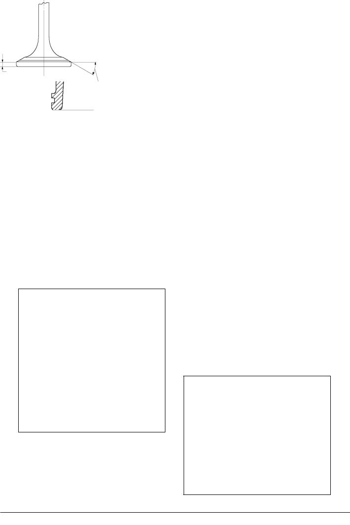
1)Grind the seating surface with a feed at an angle "A" of 30° ± 0,10°0. .
2)Continue the grinding until a clean and uniform surface condition has been obtained.
3)Carry out the final grinding with a feed in the direction inside and outwards. Normally, the best surface quality is obtained this way.
"A" 30 ± 0,10°0
"R"
"S"
Fig 1. Valve Seat Ring
Scrapping of Valve Seat Rings
Normally, the valve seat ring can be reconditioned several times.
However, when the seat "S" has been ground to such an extent that the recess "R" disappears, see fig 1, the valve seat ring has to be scrapped and a new one must be installed, see working card 505-01.35
Reconditioning of Valve Spindle
Reconditioning by machining is carried out with the valve spindle being rotated in a turning lathe and a special grinding machine mounted on the tool post of the turning latch.
Grinding of Valve Spindle
For operation of the grinding machine, see separated instructions.
1) Grind the seating surface with a feed at an angel "A" of 30° ± 0.
0,25°.
2)Continue the grinding until a clean and uniform surface condition has been obtained.
3)Check the height "H"1 after completing the grinding, see fig 2.
"H"1 has as a minimum to be as indicated on page 500.35.
If measured to be less, the spindle has to be scrapped.
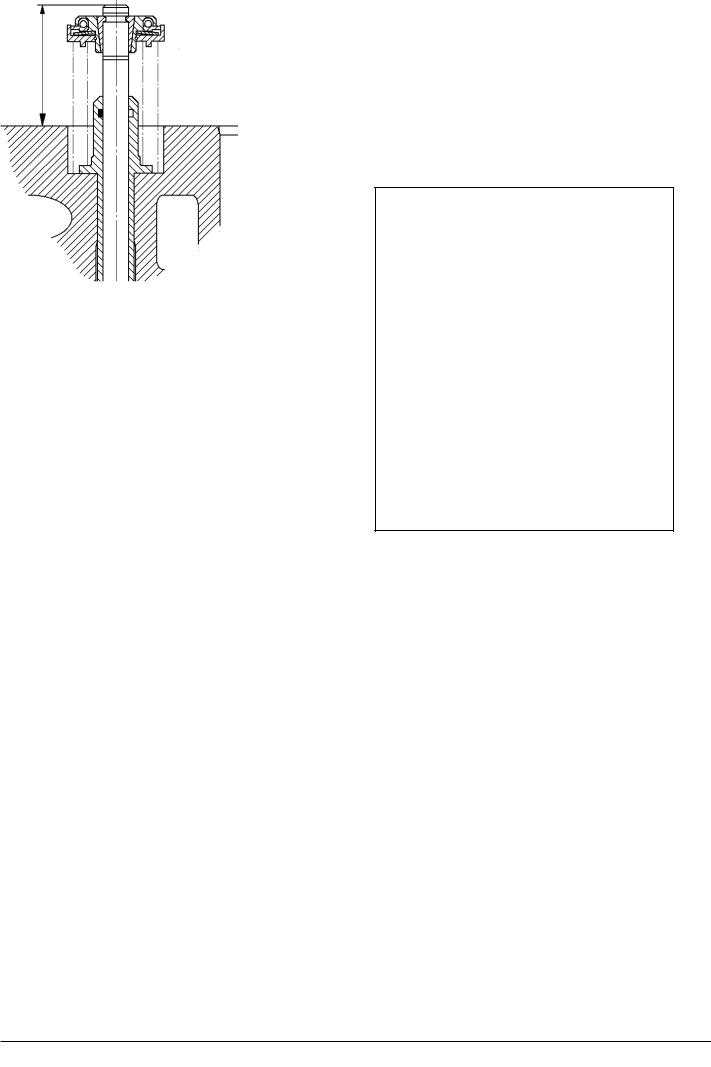
4) After assembling the valves, check - on account
"H"1 |
08028-0D/H5250/94.08.12 |
|
"A" 30° ± 0,25°0
Fig 2. Valve Spindle
95.50 - ES0S
Working Card |
Reconditioning of Valve Spindle Seat |
505-01.10 |
Page 3 (3) |
and Valve Seat Ring |
Edition 01H |
|
||
|
|
L23/30H |
of the valve motion - that distance "H"2 between the upper edge of the cylinder head and the upper edge of the valve spindle, see fig 3, does not exceed the maximum value, see page 500.35.
"H"2
Fig 3.
08028-0D/H5250/94.08.12
95.50 - ES0S

Working Card |
Valve Rotator |
505-01.15 |
Page 1 (2) |
Edition 01H |
|
|
|
|
|
|
|
|
|
L23/30H |
08028-0D/H5250/94.08.12
Safety precautions:
Stopped engine
Shut-off starting air
Shut-off cooling water
Shut-off fuel oil
Shut-off cooling oil
Stopped lub. oil circul.
Description:
Dismantling, inspection and mounting of valve rotator.
Starting position:
Valve spindle has been removed |
505-01.05 |
Related procedure:
Mounting of valve spindles |
505-01.05 |
Manpower: |
|
|
|
Working time |
: |
1/2 |
hour |
Capacity |
: |
1 |
man |
Data: |
|
|
|
Data for pressure and tolerance |
(Page 500.35) |
Data for torque moment |
(Page 500.40) |
Declaration of weight |
(Page 500.45) |
Special tools:
Plate no |
Item no |
Note |
52005 051
Hand tools:
Small screwdriver.
Ring and open-end spanner 24 mm.
Replacement and wearing parts:
Plate no |
Item no |
Qty/ |
95.50 - ES0S

5 05-01.15 |
Valve Rotator |
Working Card |
Edition 01H |
Page 2 (2) |
|
|
|
|
|
|
|
L23/30H
Inspection of Rotocap
Dirt especially in the ball pockets due to residues in the oil (abrasives, combustion products), can cause the individual parts to become stuck, and hinders the movement of the balls.
Rotocap valve rotators need no servicing under normal operating conditions.
Rotator performance is satisfactory when the valve rotates visibly and evenly.
Dismantling of Rotocap
See working card 505-01.05, point 3 to 9.
Overhaul of Rotator
1)Clean the valve rotator.
2)Inspect for wear and ball impressions.
3)Remove the retaining ring and disassemble the individual parts.
4)Replace parts showing wear grooves or depressions formed by the balls.
5)Insert the balls and the tangential springs.
Note! All balls on the inclined races of the ball pockets must point in the same direction, see fig. 1.
The inner ring of the spring washer should rest on the retainer body.
Note! Having assembled the valve rotator in dry condition it should be placed in clean lubricating oil for a short period of time.
Fig 1.
Mounting of Rotocap
See working card 505-01.05, point 3 to 9, opposite direction.
08028-0D/H5250/94.08.12
95.50 - ESOS

Working Card |
Replacement of Valve Guide |
505-01.20 |
Page 1 (2) |
Edition 01H |
|
|
|
|
|
|
|
08028-0D/H5250/94.08.12
L23/30H
Safety precautions:
Stopped engine
Shut-off starting air
Shut-off cooling water
Shut-off fuel oil
Shut-off cooling oil
Stopped lub. oil circul.
Description:
Dismantling and mounting of valve guide for inlet and exhaust valve.
Starting position:
Valve spindle has been removed |
505-01.05 |
Related procedure:
Mounting of valve spindles |
505-01.05 |
Manpower: |
|
|
|
Working time |
: |
3/4 |
hour |
Capacity |
: |
1 |
man |
Data: |
|
|
|
Data for pressure and tolerance |
(Page 500.35) |
Data for torque moment |
(Page 500.40) |
Declaration of weight |
(Page 500.45) |
Special tools:
Plate no |
Item no |
Note |
Hand tools:
Hammer.
Nitrogen (N2), or similar.
Mandrel for knocking out the valve guide.
Replacement and wearing parts:
Plate no. |
Item no. |
Qty/ |
50501 |
363 |
4/cyl |
50501 |
218 |
4/cyl |
95.50 - ES0S
505-01.20 |
Replacement of Valve Guide |
Working Card |
Edition 05H |
Page 2 (2) |
|
|
|
|
|
|
|
L23/30H
When to Replace the Valve Guide
If the clearance exceeds the max. limit, see page 500.35, the valve guide must be replaced.
Dismounting of Valve Guide
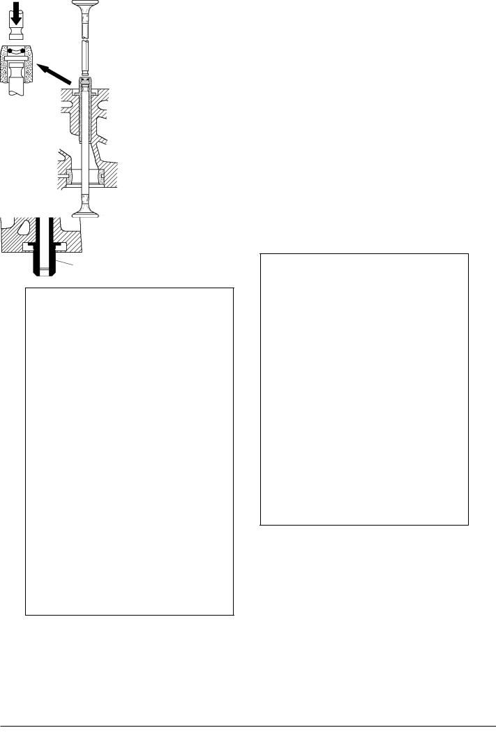
1) Knock the valve guide out from the bottom of the cylinder head, by means of a mandrel, which has a shoulder turning that fits into the valve guide, see fig 1.
4)Before mounting - cool down the new valve guide to approx. -70°C with nitrogen or similar.
5)Insert the valve guide into the bore.
6)Knock slightly with the mandrel and a hammer. Note! The shoulder of the valve guide must bear against the cylinder head, by knocking slightly with the mandrel and a hammer.
Valve seat ring
Mandrel
Valve guide
Fig 1.
2)Clean the bore of the cylinder head carefully.
3)Inspect for marks that can prevent mounting of new valve guide.
Fig 2.
7) Before mounting of the valve spindle insert a new O-ring in the valve guide.
Correct mounting can easily be done by the use of two valve spindles as mounting tool, one spindle to be used as support and the other spindle to be used for pushing the O-ring downwards.
Screw-drivers or other sharp tools should never be used for this purpose.
8) For mounting of valve spindle, see working card 505-01.05.
08028-0D/H5250/94.08.12
95.50 - ESOS

Working Card |
Indicator Valve |
505-01.26 |
Page 1 (2) |
Edition 01H |
|
|
|
|
|
|
|
|
|
L23/30H |
Safety precautions:
Stopped engine

 Shut-off starting air
Shut-off cooling water
Shut-off fuel oil
Shut-off cooling oil
Stopped lub. oil circul.
Description:
Dismounting, inspection and mounting of indicator valve.
Starting position:
Related procedure:
Man power: |
|
|
|
Working time |
: |
1/2 |
hour |
Capacity |
: |
1 |
man |
Data: |
|
Data for pressure and tolerance |
(Page 500.35) |
Data for torque moment |
(Page 500.40) |
Declaration of weight |
(Page 500.45) |
Special tools:
Plate No |
Item No |
Note |
Hand tools: |
|
Ring and open-end spanner |
10 mm |
Ring and open-end spanner |
27 mm |
Steel brush |
|
Copaslip |
|
Replacement and wearing parts:
Plate No |
Item No |
Qty./ |
50508 |
037 |
1/Cyl. |
95.50 - ES0S-G
505-01.26 |
Indicator Valve |
Working Card |
Edition 01H |
Page 2 (2) |
|
|
|
|
|
|
|
L23/30H
Maintenance
Under normal working conditions the indicator valve requires very little maintenance except inspection in connection with the normal cylinder cover overhaul.
Inspection of the Indicator Valve
1. Disassemble the indicator valve.
2. Check the valve seat and the cone for "burning through".
If the valve seat in the housing is "burned", the entire valve is to be replaced.
3. Clean and lubricate all components before remounting.
4. Ensure that the spindle is in "OPEN" position when assembling the valve.
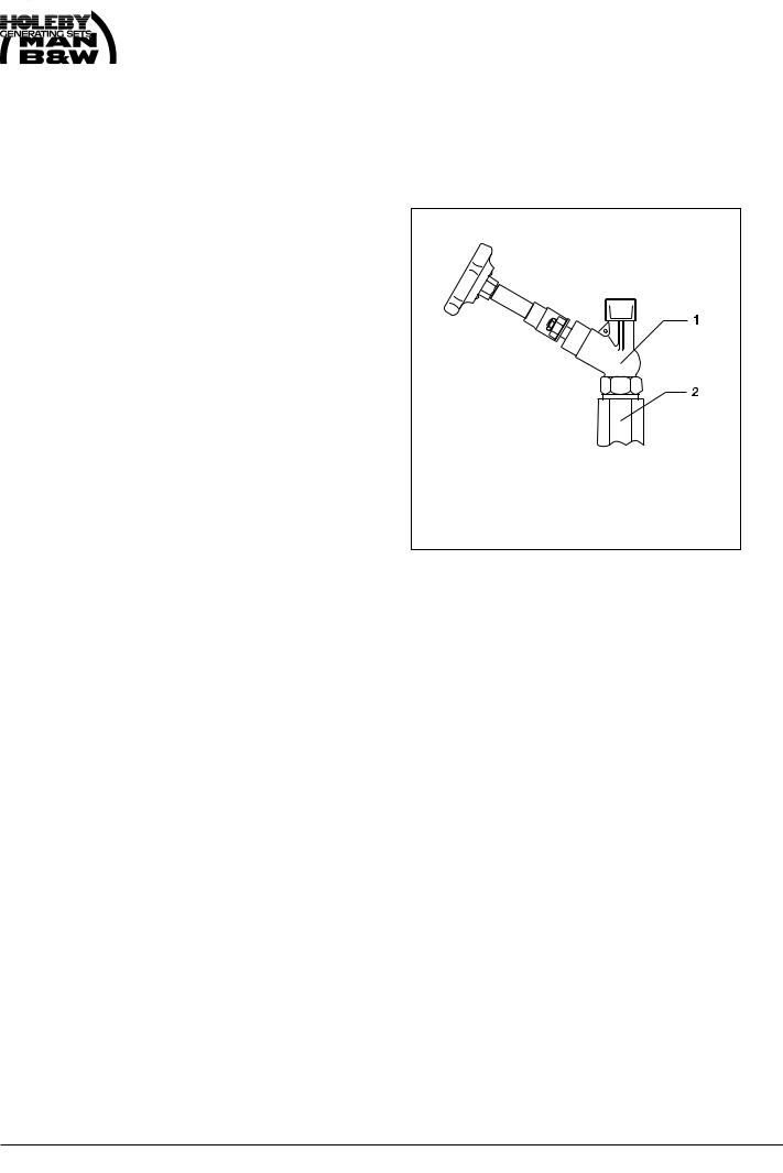
1.Indicator valve, complete
2.Connecting piece
Fig 1 Indicator valve.
NOTE: Otherwise, cone and seat may be damaged.
95.50 - ES0S-G

Working Card |
Replacement of Sleeve for Fuel Injector |
505-01.30 |
Page 1 (2) |
Edition 01H |
|
|
|
|
|
|
|
|
|
L23/30H |
Safety precautions: |
Special tools: |
|
|
Stopped engine |
Plate No |
Item No |
Note |
Shut-off starting air |
|
|
|
Shut-off cooling water |
|
|
|
Shut-off fuel oil |
|
|
|
Shut-off cooling oil |
|
|
|
Stopped lub. oil circul. |
|
|
|
Description: |
|
Dismounting, inspection and mounting of sleeve |
|
for fuel injector. |
Hand tools: |
|
Brass mandrel. |
|
Hammer. |
|
Lub. oil. |
Starting position: |
Two small screw-drivers. |
|
Loctite 572. |
The cylinder head has been dis- |
|
mounted from engine |
505-01.00 |
The fuel injector has been removed |
514-01.10 |
Related procedure:
Mounting of fuel valve |
514-01.10 |
Man power: |
|
|
|
Replacement and wearing parts: |
||
Working time |
: |
1 |
hour |
Plate No |
Item No |
Qty/ |
Capacity |
: |
1 |
man |
|
|
|
|
|
|
|
50501 |
039 |
1/cyl. |
Data: |
|
|
|
50501 |
040 |
1/cyl. |
|
|
|
|
50501 |
052 |
1/cyl. |
Data for pressure and tolerance |
(Page 500.35) |
|
|
|||
Data for torque moment |
|
(Page 500.40) |
|
|
||
Declaration of weight |
|
|
(Page 500.45) |
|
|
|
96.19 - ES0S