

7 семестр (Бормотов А) / 1man_bw_l23_30_chn_23_30_instruktsiya_po_ekspluatatsii_1 / MAN-BW L23-30 H Vol-1 (Instruction)+
.pdfDescription |
Freshwater System Treatment |
504.40 |
|
Page 3 (5) |
Edition 02 |
||
|
|||
|
|
||
|
|
|
|
|
|
General |
08028-0D/H5250/94.08.12
A chloride content in the cooling water higher than the 50 ppm specified might, in exceptional cases be tolerated. However, in that case the upper limit specified by the individual inhibitor supplier must not be exceed.
A clear record of all measuring results should be kept, so that the actual condition and trend of the system may be currently ascertained and evaluated.
A sudden or gradual decrease in pH value, or an increase of the sulphate content, may indicate exhaust gas leakage. The pH value can be increased by adding inhibtor; however, if major quantities are necessary, the water should be replaced.
Every third month a cooling water sample should be sent ashore for laboratory analysis, in particular to ascertain the contents of inhibtor, sulphate, and iron, as well as the total salinity of the water.
Cleaning and Inhibiting Procedure
The engine must not be running during the cleaning procedure, as this may involve the risk of overheating when draining.
Degreasing
Use clean tap water for filling-up. The cooling water in the system can be used, if it does not contain inhibitors.
Heat the water to 60° C and circulate the water continuously.
Drain to lowest water level in expansion tank.
Add the amount of degreasing chemical specified by the supplier, preferably from the suction side of the freshwater pump.
Drain to lowest water level in the expansion tank directly afterwards.
Circulate the cleaning chemical for the period specified by the supplier.
The cooling water system must not be kept under pressure.
Check, and repair any leaks.
Drain the system and fill up completely with clean tap water, in order to flush out any oil or grease from the tank.
Circulate the water for 2 hours, and drain again.
Descaling with Acid Solution
Fill up with clean tap water and heat to 70-75° C.
Dissolve the necessary dosage of acid compound in a clean iron drum with hot water.
Fill the drum half up with water and slowly add the acid compound, while stirring vigorously. Then fill the drum up completely with hot water while continuing to stir (e.g. using a steam hose).
Be careful - use protective spectacles and gloves.
For engines which have been treated before the trial trip, the lowest concentration recommended by the supplier will normally be sufficient.
For untreated engines, a higher concentration - depending on the condition of the cooling system - will normally be necessary.
Drain some water from the system and add the acid solution via the expansion tank.
The cooling water system must not be put under pressure.
Keep the temperature of the water between 70° C and 75° C, and circulate it constantly. The duration of the treatment will depend on the degree of fouling. Normally, the shortest time recommended by the supplier will be sufficient for engines which are treated before the trial trip. For untreated engines, a longer time must be reckoned with. Check every hour, for example with pH-paper, that the acid in the solution has not been used up.
00.11ES1

504.40 |
Freshwater System Treatment |
Description |
|
Edition 02 |
Page 4 (5) |
||
|
|||
|
|
||
|
|
|
General
A number of descaling preparations contain colour indicators which show the state of the acid solution. If the acid content is exhausted, a new acid solution can be added, in which case, the weakest recommended concentration should be used.
The solubility of acids in water is often limited. Therefore if, in exceptional cases, a large amount is required, descaling can be carried out in two stages with a new solution of compound and clean water. Normally the supplier will specify the maximum solubility.
After completing the descaling, drain the system and flush with water. Acid residues can be neutralized with clean tap water containing 10 kg soda per ton of water. Circulate the mixture for 30 minutes, then drain and flush the system.
The cooling water system must not be put under pressure.
Continue to flush until water used is neutral (pH approx. 7).
Adding of Inhibitors
Fill up the cooling water system with water from the evaporator to the lowest water level in the expansion tank.
Weight out the quantity of inhibitors specified by the supplier and dissolve in a clean iron drum with hot water from the evaporator.
Add the solution via the expansion tank to the system. Then fill up to normal water level with water from the evaporator.
Allow the engine to run for not less than 24 hours to ensure that a stable protection of the cooling surfaces is formed.
Subsequently, test the cooling water with a test kit (available from the inhibitor supplier) to ensure that an adequate inhibitor concentration has been obtained.
This should be checked every week.
The acid content of the system oil is to be checked directly after the descaling with acid, and again 24 hours afterwards.
08028-0D/H5250/94.08.12
00.11ES1

Description |
Freshwater System Treatment |
504.40 |
|
Page 5 (5) |
Edition 02 |
||
|
|||
|
|
||
|
|
|
|
|
|
General |
|
|
Nitrite-borate corrosion inhibitors |
|
|
|
for cooling water treatment |
|
08028-0D/H5250/94.08.12
|
|
Name of Inhibitor |
|
Delivery Form |
|
Maker's minimum |
|
|
Company |
|
|
Recommended |
|||
|
|
|
|
|
|
|
Dosage* |
|
|
|
|
|
|
|
|
Castrol Limited |
Castrol |
|
|
Powder |
|
3 kg/1000 l |
|
Swindon |
Solvex WT4 |
|
|
Liquid |
|
20 l/1000 l |
|
Wiltshire, England |
Castrol |
|
|
|
|||
|
|
Solvex WT2 |
|
|
|
|
|
|
|
|
|
|
|
|
|
Drew Ameriod |
DEWT-NC |
|
|
Powder |
|
3.2 kg/1000 l |
|
Marine |
Liquidewt |
|
|
Liquid |
|
8 l/1000 l |
|
Boonton, N.J./U.S.A |
Maxiguard |
|
|
Liquid |
|
16 l/1000 l |
|
|
|
|
|
|
|
|
|
Houseman Scandinavia |
Cooltreat 651 |
|
|
Liquid |
|
5 l/1000 l |
|
3660 Stenløse |
Cooltreat 652 |
|
|
Liquid |
|
5 l/1000 l |
|
Denmark |
|
|
|
||||
|
|
|
|
|
|
|
|
Nalfleet Marine Chemicals |
Nalfleet EWT Liq |
|
|
Liquid |
|
3 l/1000 l |
|
Northwich, |
(9-108) |
|
|
|
|||
Cheshire CW8DX, England |
Nalfleet EWT 9-131C |
|
Liquid |
|
10 l/1000 l |
||
|
|
Nalfleet EWT 9-111 |
|
Liquid |
|
10 l/1000 l |
|
|
|
Nalcool 2000 |
|
|
Liquid |
|
10 l/1000 l |
|
|
|
|
|
|
||
Rohm & Haas |
RD11 DIA PROSIM |
|
Powder |
|
3 kg/1000 l |
||
(ex Duolite) |
RD25 DIA PROSIM |
|
Liquid |
|
50 l/1000 l |
||
Paris, France |
|
|
|
|
|
|
|
|
|
|
|
|
|
|
|
Unitor Rochem |
Dieselguard NB |
|
|
Powder |
|
3 kg/1000 l |
|
Marine Chemicals |
Rocor NB Liquid |
|
|
Liquid |
|
10 l/1000 l |
|
Oslo, Norway |
|
|
|
|
|
|
|
|
|
|
|
|
|
|
|
* |
Initial dosage may be larger |
|
|
|
|
|
|
The list is for guidance only and |
must not be |
The suppliers are listed in alpabetical order. |
|||||
considered complete. We undertake no responsi- |
|
|
|
|
|
||
bility for difficulties that might be caused by these or |
Suitable |
cleaners can |
normally be supplied by |
||||
other water inhibitos/chemicals. |
|
these firms. |
|
|
|||
00.11ES1

Index
Page1(1)
Description
Cylinder Head |
505 |
Cylinder Head.................................................................................................................. |
|
505.01.(01H) |
||
Working |
|
|
|
|
Dismantling |
of |
Cylinder Head.............................................................................................. |
505-01.00.(01H) |
|
Inspection of Inlet Valve, Exhaust Valve and Valve Guide.................................................. |
505-01.05.(01H) |
|||
Reconditioning of Valve Spindle Seat and Valve Seat Ring................................................ |
505-01.10.(01H) |
|||
Valve |
Rotator.......................................................................................................................... |
.505-01.15.(01H) |
||
Replacement of Valve Guide............................................................................................... |
505-01.20.(01H) |
|||
Indicator |
Valve..................................................................................................................... |
|
505-01.26.01H) |
|
Replacement of Sleeve for Fuel Injector........................................................................... |
505-01.30.(01H) |
|||
Replacement of Valve Seat Ring.................................................................................... |
505-01.35.(01H) |
|||
Mounting |
of |
Cylinder Head.................................................................................................. |
505-01.40.(01H) |
|
Inspection of Cylinder Head Cooling Water Space.............................................................. |
505-01.45.(01H) |
|||
Plates |
|
|
|
|
Cylinder |
Head................................................................................................................................. |
|
50501-01H |
|
Valve Spindles and Valve Gear.................................................................................................. |
50502-01H |
|||
Indicator Valve........................................................................................................................ |
|
50508-01H |
||
Cylinder |
Head, |
Top Cover........................................................................................................ |
50510-01H |
|

Description |
Cylinder Head |
505.01 |
Page 1 (1) |
Edition 01H |
|
|
|
|
|
|
|
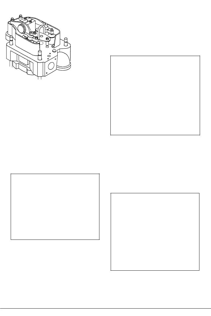
Cylinder Head
The individual cast-iron cylinder heads, one for each cylinder unit, are equipped with a centrally situated fuel injection valve, two inlet valves, two exhaust valves and one indicator cock.
The head has a thick, bore-cooled flame plate for satisfactory control of mechanical and thermal loads and stress.
The cylinder head is attached by means of 4 nuts and 4 studs screwed into deep bosses in the engine frame top plate. The nuts are tightened by means of hydraulic tools.
L23/30H
Inlet and Exhaust Valves
The inlet and exhaust valve spindles are identical and therefore interchangeable.
Thevalvespindlesaremadeofheat-resistantmaterial. Hard metal is welded on to the valve spindle seats.
The valve spindles are fitted with valve rotators which turn the spindles a little each time the valves open.
The cylinder head is equipped with replaceable seat rings for inlet and exhaust valves.
Theseatingsurfacesarehardenedinordertominimize wear and prevent dent marks, on the inlet seat by induction hardening, on the exhaust seat by hard metal armouring.
08028-0D/H5250/94.08.12
95.50 - ES0U-G
Working Card |
Dismantling of Cylinder Head |
505-01.00 |
Page 1 (2) |
Edition 01H |
|
|
|
|
|
|
|
|
|
L23/30H |
08028-0D/H5250/94.08.12
Safety precautions:
Stopped engine

 Shut-off starting air
Shut-off cooling water
Shut-off fuel oil
Shut-off cooling oil
Stopped lub. oil circul.
Description:
Dismantling of cylinder head for inspection and/or overhaul.
Starting position:
Cooling water has been drained from engine.
Related procedure:
Dismounting of piston and connecting
rod |
|
|
|
506-01.00 |
Dismounting and inspection of inlet valve, |
||||
exhaust valve and valve guide |
505-01.05 |
|||
Dismantling, overhaul and test |
|
|||
pressure of fuel oil valve |
|
514-01.10 |
||
Manpower: |
|
|
|
|
Working time |
: |
1 |
hour |
|
Capacity |
: |
2 |
men |
|
Data: |
|
|
|
|
Data for pressure and tolerance |
(Page 500.35) |
|||
Data for torque moment |
|
(Page 500.40) |
||
Declaration of weight |
|
|
(Page 500.45) |
|
Special tools: |
|
|
Plate no |
Item no |
Note |
52021 |
011 |
Oil injector, |
52021 |
011 |
(Complete) |
52021 |
501 |
4 pieces |
52021 |
513 |
1 piece |
52021 |
155 |
|
52005 |
014 |
|
52021 |
251 |
Hydraulic tools |
Hand tools:
Ring and open-end spanner, 17 mm. Ring and open-end spanner, 19 mm. Ring and open-end spanner, 27 mm. Allen key, 8 mm.
Replacement and wearing parts:
Plate no |
Item no |
Qty/ |
95.50 - ES0S
505-01.00 |
Dismantling of Cylinder Head |
Working Card |
|
Edition 01H |
Page 2 (2) |
||
|
|||
|
|
|
|
L23/30H |
|
|
Draining of cooling water, disconnection of pipes etc.
1)Open the drain cock and vent cock for cooling water.
2)Take off the top cover.
3)Take off the front cover which gives access to the injection pump.
4)Disconnect the fuel oil high-pressure pipe.
5)Disconnect the rocker arm lubricating oil pipe.
6)Remove the thermometer attachment branch (cooling water outlet pipe).
7)Remove the exhaust pipe flange screws.
8)Remove the cylinder head nuts, see Fig 1, by means of hydraulic jacks. See working card 52001.05.
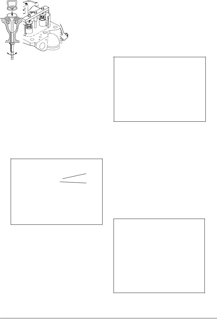
Fig 1
Mounting of Lifting Tool while the Fuel Injection Valve is Placed in the Cylinder Head.
9)Disconnect the two nuts which is holding down the fuel injection valve.
10)Remove the two distance pieces.
11)Mount the lifting tool by means of the two nuts. See Fig 2.
Fig 2
Mounting of Lifting Tool with the Fuel Injection Valve is Removed from the Cylinder Head.
12)Mount the two-distance pieces to the studs.
13)Mount the lifting tool by means of the two nuts. See Fig 3.
Fig 3
14)Attach the hook to the lifting tool and lift the cylinder head away.
08028-0D/H5250/94.08.12
95.50 - ES0S
Working Card |
Inspection of Inlet Valve, Exhaust Valve and Valve Guide |
505-01.05 |
Page 1 (3) |
Edition 01H |
|
|
|
|
|
|
|
08028-0D/H5250/94.08.12
L23/30H
Safety precautions:
Stopped engine
Shut-off starting air
Shut-off cooling water
Shut-off fuel oil
Shut-off cooling oil
Stopped lub. oil circul.
Description:
Dismounting of inlet and exhaust valve, inspection of valve guide and mounting of inlet and exhaust valve.
Starting position: |
|
Cylinder head, dismantled from |
|
engine |
505-01.00 |
Related procedure: |
|
Reconditioning of valve spindle seat |
|
and valve seat ring |
505-01.10 |
Valve rotator |
505-01.15 |
Replacement of valve guide |
505-01.20 |
Replacement of valve seat ring |
505-01.35 |
Mounting of cylinder head |
505-01.45 |
Manpower: |
|
|
|
Working time |
: |
1 |
hour |
Capacity |
: |
1 |
man |
Data: |
|
|
|
Data for pressure and tolerance |
(Page 500.35) |
Data for torque moment |
(Page 500.40) |
Declaration of weight |
(Page 500.45) |
Special tools: |
|
|
Plate no. |
Item no. |
Note. |
52005 |
014 |
|
52005 |
051 |
|
52005 |
254/301 |
Extra tools |
52005 |
553 |
|
Hand tools:
Ring and open-end spanner, 24 mm. Small screwdriver.
Measuring tools.
Replacement and wearing parts:
Plate no |
Item no |
Qty/ |
60501 |
363 |
4/cyl. |
95.50 - ES0S
505-01.05 |
Inspection of Inlet Valve, Exhaust Valve and Valve Guide |
Working Card |
Edition 01H |
Page 2 (3) |
|
|
|
|
|
|
|
L23/30H
Dismantling of Inlet and Exhaust Valve Spindles
1) Land and fasten the cylinder head upon the special work table and remove the lifting tool.
Or as an Alternative:
Land the cylinder head on the floor upon wooden supports and remove the lifting tool.
2) Mount the supporting devices for the valve spindle heads on the work table.
Or as an alternative:
Place wooden blocks under the valve spindle heads.
3) Turn back the rocker arm and remove the spring-loaded valve bridge over the valve spindles.
A
B
Fig 1.
4)Mount the tool for mounting af valves, see fig 2.
5)Compress the valve springs by tightening nut A, see fig 1.
6)Remove the cone rings, see fig 2.
7)Release the springs again.
8)Remove nut A and traverse B, see fig 1.
9)Remove valve rotator and springs.
Fig 2.
table and take out the valve spindle.
11) Repeat point 4 - 10 to remove the two other valve spindles.
Inspection of Valves/Valve Seats
A slight grinding of valve/valve seat can be carried out by means of the handle as shown, see fig 3.
If the valve seat is heavily burnt or scarred, it should be ground using the valve seat grinder, see working card 505-01.10.
Inspection of Valve Guide
Fig 3.
08028-0D/H5250/94.08.12
10)Remove the supporting devices under the work
95.50 - ES0S
Working Card |
Inspection of Inlet Valve, Exhaust Valve and Valve Guide |
505-01.05 |
Page 3 (3) |
|
Edition 01H |
|
|
|
|
|
|
|
|
L23/30H |
Too much clearance between valve spindle and spindle guide may cause:
-increased lub. oil consumption.
-fouling up of the spindle guide and thus give the risk of a sticking valve spindle.
Too much clearance also means insufficient guidance of the valve spindle, and thus bad alignment between spindle head and valve seat ring.
In connection with overhaul of the cylinder head, the valve spindle guides should be cleaned, inspected and measured for wear.
If the inner diameter of the valve spindle guide exceeds the tolerance, see page 500.35, the valve spindle guide must be replaced. See working card 505-01.20.
Mounting of Valve Spindle
12) For mounting of valve spindle follow the
Fig 4.
instructions in point 4 - 10 in reversed order.
Max inner diameter,
see page 500.35.
08028-0D/H5250/94.08.12
95.50 - ES0S