

7 семестр (Бормотов А) / 1man_bw_l23_30_chn_23_30_instruktsiya_po_ekspluatatsii_1 / MAN-BW L23-30h project-guide
.pdf1609580-8.3 Page 1 (1)
Silencer with Spark Arrestor, Damping 25 dB (A) |
E 16 04 5 |
|
|
L23/30H
Design
The operating of the silencer is based on the absorption system. The Gasflow passes straight-through a perforated tube, surrounded by highly effecient sound absorbing material, thus giving an excellent attenuation over a wide frequency range.
The operation of the spark arrestor is based on the centrifugal system. The gases are forced into a rotary movement by means of a number of fixed blades. The solid particles in the gases are thrown against the wall of the spark arrestor and collected in the soot box. (Pressure loss, see graphic)
The silencer is delivered without insulation and fastening fittings.
|
|
D |
|
|
|
|
E |
|
C |
|
E |
|
|
|
|
|
|
J |
|
|
F |
|
B |
|
A |
G |
H |
|
Spark arrestor |
Spark arrestor |
|
|
|
|
|
type (b) |
type (a) |
|
|
|
|
|
|
|
|
|
K number of holes |
|
M |
P |
P |
M |
|
|
O |
Installation
The silencer/spark arrestor has to be installed as close to the end of the exhaust pipe as possible.
|
|
1000 |
|
|
|
800 |
|
|
|
600 |
|
|
C. |
400 |
|
|
T300°at |
300 |
|
|
|
||
|
Pa) |
200 |
|
|
150 |
||
|
~ 10 |
||
|
100 |
||
|
w |
||
|
80 |
||
|
(mm |
||
|
60 |
||
|
loss |
||
|
50 |
||
|
|
||
|
Pressure |
40 |
|
øL |
30 |
||
|
|||
|
|
20 |
|
|
|
10 |
10 15 20 30 40 60 80100
Gas velocity (m/s)
Silencer type (A)
Damping |
Cyl. |
A |
B |
C |
D |
E |
F |
G |
H |
J |
K |
L |
M |
O |
P |
Weight |
|
dB (A) |
type |
(DN) |
kg |
||||||||||||||
|
|
|
|
|
|
|
|
|
|
|
|
|
|||||
|
|
|
|
|
|
|
|
|
|
|
|
|
|
|
|
|
|
25 |
5+6 (720/750) |
350 |
838 |
2445 |
2645 |
100 |
858 |
490 |
445 |
16 |
12 |
22 |
350 |
270 |
400 |
550 |
|
|
|
|
|
|
|
|
|
|
|
|
|
|
|
|
|
|
|
25 |
7+8 (720/750) |
400 |
938 |
2965 |
3185 |
110 |
958 |
540 |
495 |
16 |
16 |
22 |
350 |
290 |
600 |
700 |
|
|
6 (900 rpm) |
|
|
|
|
|
|
|
|
|
|
|
|
|
|
|
|
|
|
|
|
|
|
|
|
|
|
|
|
|
|
|
|
|
|
25 |
7+8 (900 rpm) |
450 |
1084 |
3465 |
3685 |
110 |
1104 |
595 |
550 |
16 |
16 |
22 |
350 |
300 |
850 |
950 |
|
|
|
|
|
|
|
|
|
|
|
|
|
|
|
|
|
|
|
Silencer type (B) |
|
|
|
|
|
|
|
|
|
|
|
|
|
|
|
||
|
|
|
|
|
|
|
|
|
|
|
|
|
|
|
|
|
|
Damping |
Cyl. |
A |
B |
C |
D |
E |
F |
G |
H |
J |
K |
L |
M |
O |
P |
Weight |
|
dB (A) |
type |
(DN) |
kg |
||||||||||||||
|
|
|
|
|
|
|
|
|
|
|
|
|
|||||
|
|
|
|
|
|
|
|
|
|
|
|
|
|
|
|
|
|
25 |
5+6 (720/ |
350 |
700 |
2800 |
3000 |
100 |
730 |
490 |
445 |
16 |
12 |
22 |
50 |
300 |
650 |
377 |
|
|
750) |
|
|
|
|
|
|
|
|
|
|
|
|
|
|
|
|
25 |
7+8 (720/750) |
400 |
750 |
3100 |
3400 |
150 |
780 |
540 |
495 |
16 |
16 |
22 |
100 |
300 |
700 |
470 |
|
|
6 (900 rpm) |
|
|
|
|
|
|
|
|
|
|
|
|
|
|
|
|
25 |
7+8 (900 rpm) |
450 |
800 |
3100 |
3400 |
150 |
830 |
595 |
550 |
16 |
16 |
22 |
100 |
350 |
800 |
526 |
|
|
|
|
|
|
|
|
|
|
|
|
|
|
|
|
|
|
|
Dimension for flanges for exhaust pipes is according to DIN 86044
99.39

1609584-5.3 Page 1 (1)
Silencer with Spark Arrestor, Damping 35 dB (A) |
E 16 04 6 |
|
|
L23/30H
Design
The operating of the silencer is based on the absorption system. The Gasflow passes straight-through a perforated tube, surrounded by highly effecient sound absorbing material, thus giving an excellent attenuation over a wide frequency range.
The operation of the spark arrestor is based on the centrifugal system. The gases are forced into a rotary movement by means of a number of fixed blades. The solid particles in the gases are thrown against the wall of the spark arrestor and collected in the soot box. (Pressure loss, see graphic).
The silencer is delivered without insulation and fastening fittings.
|
|
D |
|
|
|
|
E |
|
C |
|
E |
|
|
|
|
|
|
J |
|
|
F |
|
B |
|
A |
G |
H |
|
Spark arrestor |
Spark arrestor |
|
|
|
|
|
type (b) |
type (a) |
|
|
|
|
|
|
|
|
|
K number of holes |
|
M |
P |
P |
M |
|
|
O |
Installation
The silencer/spark arrestor has to be installed as close to the end of the exhaust pipe as possible.
|
|
1000 |
|
|
|
800 |
|
|
|
600 |
|
|
C. |
400 |
|
|
T300°at |
300 |
|
|
|
||
|
Pa) |
200 |
|
|
150 |
||
|
~ 10 |
||
|
100 |
||
|
w |
||
|
80 |
||
|
(mm |
||
|
60 |
||
|
loss |
||
|
50 |
||
|
|
||
|
Pressure |
40 |
|
øL |
30 |
||
|
|||
|
|
20 |
|
|
|
10 |
|
|
|
|
|
|
|
|
|
|
|
|
10 |
15 |
20 |
30 |
40 |
60 |
80100 |
||||
|
|
|
|
|
|
|
|
|
|
|
|
|
|
|
Gas velocity (m/s) |
|
|
|||||
Silencer type (A) |
|
|
|
|
|
|
|
|
|
|
|
|
|
|
|
|
|
|
|
|
|
|
|
|
|
|
|
|
|
|
|
|
|
|
|
|
|
|
|
|
|
|
|
|
|
Damping |
Cyl. |
A |
B |
C |
D |
E |
F |
|
G |
H |
J |
K |
|
L |
|
M |
|
|
O |
P |
|
Weight |
dB (A) |
type |
(DN) |
|
|
|
|
|
|
kg |
|||||||||||||
|
|
|
|
|
|
|
|
|
|
|
|
|
|
|
|
|
|
|
||||
|
|
|
|
|
|
|
|
|
|
|
|
|
|
|
|
|
|
|
|
|
|
|
35 |
5+6 (720/ |
350 |
838 |
3445 |
3645 |
100 |
858 |
|
490 |
445 |
16 |
12 |
|
22 |
|
350 |
|
270 |
400 |
|
700 |
|
750) |
|
|
|
|
|
|||||||||||||||||
|
|
|
|
|
|
|
|
|
|
|
|
|
|
|
|
|
|
|
|
|
|
|
|
|
|
|
|
|
|
|
|
|
|
|
|
|
|
|
|
|
|
|
|
|
|
35 |
7+8 (720/ |
400 |
938 |
3965 |
4185 |
110 |
958 |
|
540 |
495 |
16 |
16 |
|
22 |
|
350 |
|
290 |
600 |
|
850 |
|
750) |
|
|
|
|
|
|||||||||||||||||
|
6 (900 rpm) |
|
|
|
|
|
|
|
|
|
|
|
|
|
|
|
|
|
|
|
|
|
35 |
7+8 (900 |
450 |
1084 |
4715 |
4935 |
110 |
1104 |
|
595 |
550 |
16 |
16 |
|
22 |
|
350 |
|
300 |
850 |
|
1200 |
|
rpm) |
|
|
|
|
|
|||||||||||||||||
|
|
|
|
|
|
|
|
|
|
|
|
|
|
|
|
|
|
|
|
|
|
|
|
|
|
|
|
|
|
|
|
|
|
|
|
|
|
|
|
|
|
|
|
|
|
Silencer type (B) |
|
|
|
|
|
|
|
|
|
|
|
|
|
|
|
|
|
|
|
|
|
|
|
|
|
|
|
|
|
|
|
|
|
|
|
|
|
|
|
|
|
|
|
|
|
Damping |
Cyl. |
A |
B |
C |
D |
E |
F |
|
G |
H |
J |
K |
|
L |
|
M |
|
|
O |
P |
|
Weight |
dB (A) |
type |
(DN) |
|
|
|
|
|
|
kg |
|||||||||||||
|
|
|
|
|
|
|
|
|
|
|
|
|
|
|
|
|
|
|
||||
|
|
|
|
|
|
|
|
|
|
|
|
|
|
|
|
|
|
|
|
|
|
|
35 |
5+6 (720/ |
350 |
850 |
3550 |
3750 |
100 |
880 |
|
490 |
445 |
16 |
12 |
|
22 |
|
50 |
|
300 |
650 |
|
627 |
|
|
750) |
|
|
|
|
|
|
|
|
|
|
|
|
|
|
|
|
|
|
|
|
|
35 |
7+8 (720/750) |
400 |
950 |
4100 |
4400 |
150 |
980 |
|
540 |
495 |
16 |
16 |
|
22 |
|
100 |
|
300 |
700 |
|
885 |
|
|
6 (900 rpm) |
|
|
|
|
|
|
|
|
|
|
|
|
|
|
|
|
|
|
|
|
|
35 |
7+8 (900 |
450 |
1050 |
4350 |
4650 |
150 |
1080 |
|
595 |
550 |
16 |
16 |
|
22 |
|
100 |
|
350 |
800 |
|
1140 |
|
rpm) |
|
|
|
|
|
|||||||||||||||||
|
|
|
|
|
|
|
|
|
|
|
|
|
|
|
|
|
|
|
|
|
|
|
|
|
|
|
|
|
|
|
|
|
|
|
|
|
|
|
|
|
|
|
|
|
|
Dimension for flanges for exhaust pipes is according to DIN 86044 |
|
|
|
|
|
|
|
|
|
|
|
|
|
|
||||||||
99.39
Speed Control System
B 17

1607583-4.3 |
|
|
Starting of Engine |
B 17 00 0 |
Page 1 (1) |
|
|
||
|
|
|
|
|
|
|
|
|
General |
Load |
|
|
|
|
|
C |
B |
|
|
50 |
|
A |
|
|
|
|
|
|
|
0 |
1 |
2 |
3 |
12 minutes |
08028-0D/H5250/94.08.12
The engine may be started and loaded according to the following procedure:
A: Normal start without preheated cooling water. Only on MDO.
B: Normal start with preheated cooling water. MDO or HFO.
C: Stand-by engine. Emergency start, with preheated cooling water, intermediate prelubricating or continuos prelubricating.
MDO or HFO.
Starting on HFO
During shorter stops or if the engine is in stand-by on HFO the engine must be preheated.
During preheating the cooling water outlet temperature should be kept as high as possible at least 60° C (± 5°C) -either by means of cooling water from engines which are running or by means of a built-in preheater.
If the engine normally runs on HFO preheated fuel must be circulated through the engine while preheating although the engine has run or has been flushed on MDO for a short period.
Starting on MDO
For starting on MDO there are no restrictions exept lub. oil viscosity may not by higher than 1500 cSt. (0° C for lub. oil SAE 30, or 10° C for SAE 40).
Initial ignition may be difficult if the engine and ambient temp. are lower than 0° C, and the cooling water temperature is lovwer than 15° C.
Prelubricating
The engine shall always be prelubricated 2 minutes prior to start if there is not intermittent or continuos prelubricating installed. Intermittent prelub. is 2 min. every 10 minutes.
99.03
1639468-5.0 Page 1 (1)
Governor |
B 17 01 1 |
|
|
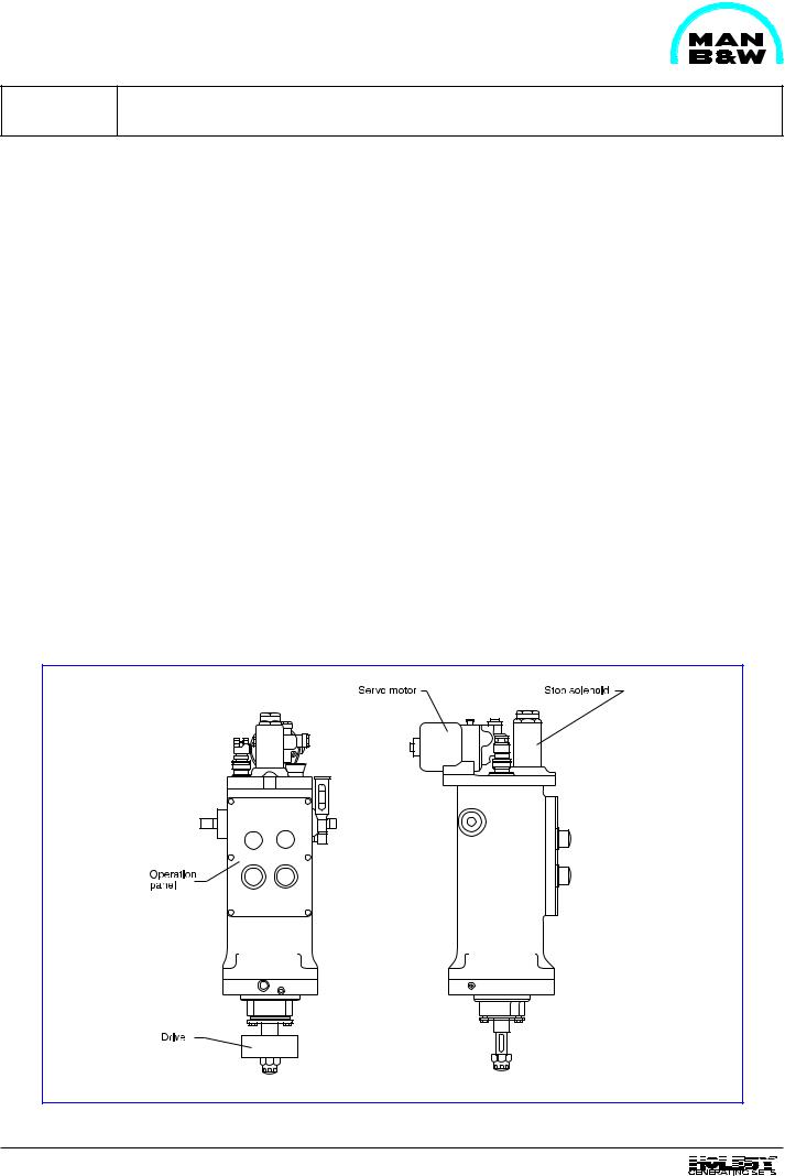
Governor Type
As standard, the engines are equipped with a mechanical - hydraulic Woodward governor type UG8D.
Speed Adjustment
Electrical remote adjustment or manual adjustment on the governor.
Speed Adjustment Range
Between -5% and +10% of the nominal speed at idle running.
Droop
Droop adjustable between 0% and 7% of the nominel speed; normally adjusted at 3.5% speed rise when load is taken off from full load to idle running.
08028-0D\H5250\94.08.12
General
0% droop is only possible for single engines in solo operation. In the case of solo and mains parallel operation, 3 to 5% droop is required.
In the case of electronic speed control, 0% droop is possible for parallel operation as well.
Load Distribution
By the droop.
Shut-down/Stop
By shut-down or stop the stop solenoid is energized 24 V DC.
Fig 1 Woodward governor
94.17