

Phedotikov / 1 / FreeEnergy_27.01.08 / Схемотехнические / Energy Электрического разряда / Энергия Грея / efficient_power
.pdfEfficient Power Supply Suitable For Inductive Loads
Engineering Report Gray Pat. no. 4,595,975
by
Mr. Gary Magratten
26901 Ridge Rd. Willits CA 95490 ph: 707-459-1435 fax:707-459-9298
Table of Contents
Introduction
Circuit Section 1. Battery to the Transformer
Circuit Section 2. Transformer to Full Wave Bridge.
Circuit Section 3. From Full Wave Bridge; to the Capacitor#1; to the
Conversion Element Switching Tube (CSET); to the Load; to the Capacitor
#2 to the Battery.
Subsection 3A. From the Full Wave Bridge to the Capacitor#1 Subsection 3B. From Capacitor#1 to the Conversion Element
Switching Tube. (CSET)
Subsection 3C. From the CSET to the Load to Capacitor#2 Subsection 3D. From Capacitor #2 to the Battery.
Circuit Section 4. Battery Charging Circuit.
Circuit Section 5. Chopper - Vibrator Circuit Circuit Section 6. Low-Voltage Switching Circuit Subsection 6A. Mechanical Switching Subsection 6B. Solid State Switching
Subsection 6C. Laser Diode – Photo transistor Switching
Circuit Section 7. Conversion Element Switching Tube [CSET]
Circuit Section 8. Load.
Circuit Section 9. Spark Overshoot Device.

INTRODUCTION
The purpose of this report is to provide the circuit analysis, working drawings, component specifications and component manufactures for Mr. Edwin Gray’s patent number 4,595,975 - Efficient Power Supply Suitable for Inductive Loads.
This information is for SCIENTIFIC RESEARCH only in order to more fully understand the scientific principles demonstrated by Gray’s pat no. 4,595,975. In the spirit of open information and cooperation between scientist, researchers and business professionals, this information is open to the public and may be reproduced and distributed by anyone for the purpose of providing scientific research information
WARNING! Gray’s Circuit pat. no. 4,595,975 contains a very HIGH POWER CAPACITOR
that is DANGEROUS! Experimentation with this circuit requires at least the
formal education of a licensed electrician. If you perform research with this circuit,
YOU DO SO AT YOUR OWN RISK. Follow all standard safety precautions and use a proper laboratory to conduct testing.
If you follow the instructions, the circuit will work. I have confirmed this with actual test runs. It is my sincere hope that clean, efficient means to generate electricity will evolve from this information for the benefit of everyone. Mr Gary Magratten
Circuit Section 1. Battery to transformer:
The batteries should be deep cycle golf cart batteries, 12 volts and under 200 A hrs Use true deep cycle batteries. Automotive batteries are designed for high current for a short period of time. Deep cycle batteries provide steady current and can handle repeated recharging. A deep cycle battery rated at 200 A hrs should deliver 10 amps of current for 20 hrs.
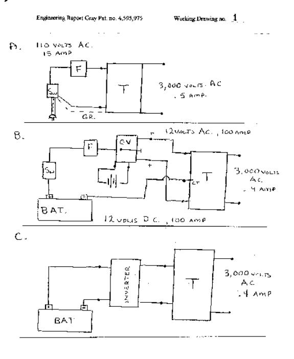
There are three ways to accomplish this section of the circuit. Working drawing no.1 show all three ways. First, and easiest for research is the use of 110 AC house current at 15 amps to the primary of a transformer and a 3,000 volt, .5 amp AC secondary. The second is a 12 volt battery, DC, to a chopper-vibrator
which produces 12 volt AC for the transformer. The design of the chopper-vibrator will be described separately later. This requires a special transformer with a 12 volt AC at 100 amps to the primary. The
primary side also requires a center tap. The secondary is 3,000 volts and .5 amps AC. The third, is to use a deep cycle battery 12 volts, 100 amps and an inverter to form 110 AC at 11 amps. The transformer should then be rated at 110
volts at II amps on the primary and 3,000 volts and .4 amps.
Include a switch and a fuse into the circuit as shown on the working drawings.

Circuit #2 - Transformer to Full Wave Bridge:
From the secondary of the transformer there is 3,000 volts and .5 amps alternating current. The full wave bridge converts the alternating current to direct current pulses. Position the diodes of the bridge for a positive terminal close to the transformer and the negative terminal away from the battery. To build a full wave bridge you can use four diodes or a one piece full wave bridge unit. The rating of the diodes is 8,000 PIV (peak inverse voltage) and .5 amp forward current.

Capacitor #1:
In subsection 3A the full wave bridge can be treated as a direct current source
with a positive terminal and a negative terminal. The voltage available is 3,000
volts at .5 amps. The positive terminal of the full wave bridge is connected to
the positive side of Capacitor #1.
The negative terminal of the full wave bridge is connected to the negative side of Capacitor #1. The positive terminal of the capacitor is directly connected to the high-voltage anode of the CSET.
The negative terminal of the battery is connected to the negative terminal of the full wave bridge. Then the negative terminal of the full wave bridge is connected to the negative side of Capacitor #1.
THIS IS VERY IMPORTANT. THE 3,OOOvoIts
.5 amp DIRECT CURRENT IS COUPLED WITH THE l2volt, 100 amps AVAILABLE FROM THE
BATTERY. THIS GIVES A 300 Kva CHARGE TO CAPACITOR #1. THIS IS VERY HIGH POWER
and DANGEROUS!
I found this difficult to understand but the technical discussion from Mr. Richard Hackenburger ( Mr. Gray’s electrical engineer clearly shows ZS6Kva of instantaneous power available from Capacitor #1.) Careful examination of the wiring diagram will confirm this statement. Pulses of direct current are built
up (technically called RAMPING) on capacitor #1 to be available for the arc in the CSET.

Capacitor #1 to the high-voltage anode of the CSET. The positive side of Capacitor # 1 is coupled directly to the high-voltage anode of the
CSET. Use #10 stranded copper wire with standard insulation and electrical tape to prevent contact with this HIGH POWER section of the circuit. The high-voltage anode is 3/16” zinc plated steel rod. This will be discussed in detail in the
CSET section.