

Phedotikov / 1 / FreeEnergy_27.01.08 / Схемотехнические / Energy Электрического разряда / Free Energy Circuits
.pdfTHE FREE ENERGY CIRCUIT
By Geoff Egel
This article appeared in Australian Magazine Hard Evidence May/June 2002
Many will recognize the above circuit as a schematic for the early crystal radio set receivers that many radio enthusiasts built when young ,I built many in the early nineteen sixties not only to receive the local AM radio stations but with a suitable antenna and by changing the coil windings ,size and diameter I was able to receive Radio Australia and the then ship to shore radio telephone service from Sydney Australia and, I believe this was over a thousand kilometers away from where I lived at the time.
Remember the crystal set was able to let your listen to local radio stations without need for a power supply but run from the power sent out by the radio station itself.

Others with a little imagination can see it as a half wave dc power rectification schematic .
This is an interesting circuit and as is the case in nature where nature uses common designs for each of its various creation, so it may be the case that the circuit designs as shown above may be the common circuit that may be useful in uncovering the secrets to free energy.
After seeing the simple circuit as described by Dr Peter Lindemann Dsc I was stuck by the similarity between the circuits that other free energy researchers claimed to have used in their invention.
The basic concept as I understand it, is a high frequency high voltage, low current rectified and then used to charge a bank of high value and high voltage capacitors and then to discharge them in pulse mode for brief period of time, nano seconds in fact by, means of a high speed electronic switching circuit or mechanical device and a rectification method that will only allow the high voltage charge to flow in only one direction .
The switching device of firing device could be a rotating spark gap as used by Nicola Tesla or some high speed electronic device, it is my belief that only glass tubes such as diodes or triode valves are really good at this and not transistors as they cannot handle the high voltage and high current produced in these devices without burning themselves out..
This type of design can produce a very high amperage current for a faction a second that can used to do some useful work if properly harnessed.
A point to remember is that Paul Baumann claims to have built his first device called the Testakica when in prison and as such did not have access to exotic materials as is often described in other theories of how the Testakica free energy machine was said to have worked.
Please note engineers from Europe have actually seen the device working.
One would conclude from this, that as such, that the home experimenter should also be able to build such a device from material source from around the home and the local area.
REMEMBER THE KISS PRINCIPLE AND KEEP IT SIMPLE STUPID.
Getting the high voltage to start with.
There are two main types of methods that I am aware of are they are.
STEP UP VOLTAGE transformer
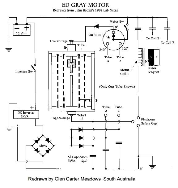
As used by Edwin Gray in his invention the charging circuit is basically a 12 volt battery being driven by vibrating relays to pulse the power through a step up transformer to raise voltage from 12 volt to approx 3000 volts this then, is rectified and used to charge a bank of high voltage capacitors.
This bank of capacitors is then discharged for a nano seconds period into special design tube which seems nothing than a copper rod a spark gap some carbon with maybe enclosed oxygen and a series of concentric rings around the spark gap and the resulting power collected on those rings is then fed to the earth via a air induction transformer or to the positive terminal of the charging batteries .

The power appearing at secondary of this air induction transformer is then used to power the motoring coils of the specially design motor.
High Voltage Induction Coil

Another method used in early X-ray machine and also Marconi in his first radio transmission across the Atlantic ocean was the induction coil basically a two coils wound on a metal rod a small number of primary windings in heavier gauge wire and large number of finer gauge winding ,basically a step up transformer using the primary magnetic field to operate a switch that controls the power to the primary winding.
This causes the magnetic field in the primary coil to build up and down which then causes an induction an alternating high voltage output in the secondary coil.(most likely a square wave)
A home made Wimshurst Machine
Electrostatic generation of high Potential.
The People at the Swiss Community of Merithnita seem to be using a Wimshurst machine to generate the high voltage needed to run their free energy device and home workshop handyman should be able to construct one for themselves
Check the following website for more details on this device
http://energy21.org/swiss.htm
The device was a popular means to generate high voltage in the late 19 century and early 20 century .
It role was at some stage used to provide the high voltage needed for early x-ray machines in hospitals but today is usually superceded by the modern electronic version or the Van de Graaf machine in modern physics laboratories today.
The Wimshurst design is basically two counter rotating disks of a plastic or glass
material upon which are place metal foil leaf sections spaced and separated from each other around the disk surface..
These twin’s discs are spun in opposing directions on a common axle by means of a belt either hand driven or motor driven.
Brushes mounted at various points near the disk’s metal plates but not touching the disk collect the charge and usually then conduct it to a capacitor storage position or discharge the built up charge through a spark gap.
ANOTHER DEVICE IS CALLED A DIROD invented by A.D.MOORE
This a flat circular plastic disk upon which have been glued several conductive metal rod’s mounted in radial positions around the disk.
This disk is spun by means of a hand crank
Four pickup positions mounted along side the spinning rods pick up the charge through conductive foil or conductive plastic as used in computer electronic parts packaging and then either discharge the high voltage buildup through a spark gap or charge a capacitor bank.
It is my conclusion that the Single Swiss disk version of the Testatika makes use of the Dirod principle in it’s design of the smaller version of the single disk Testatika machine to generate the high voltage potential.
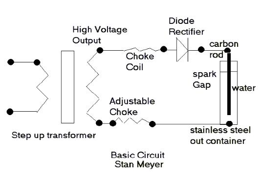
I refer to the circuit diagram as reproduced below which consists of transformer which raises the voltage to several thousand volts which charges a capacitor bank to several thousand volts and then discharges it across a spark gap.
In the original patent drawing as produced by Stan Meyers the transformer appears to be an automotive step up transformer but as friend has indicated to me that the coil would be unable to handle the frequencies needed to make this circuit perform ,he however has removed the center core material and has found he is able to use it at high frequencies.
My friend is using a waveform generator (square wave ) to drive an electronic high voltage car ignition system as used in modern automobiles ,I think he had made it from kit.
I saw him using this setup to drive high voltage sparks across some ½ inch carbon rods and it seemed rather impressive.
He used a car battery as the power source.
A POSSIBLE STAN MEYERS CIRCUIT
http://www.Fortunecity.com/greenfield/bp/16/stanleymeyer.htm
This circuit appears to charge a water cell with a high voltage source , Stan Meyers claims he had to resonated the water cell with a high voltage charge and then when the dielectric would break down, the resulting high current through the water causes electrolysis and breaks it down into hydrogen and oxygen as well as other dissolved gases in the water that could then be used to power a motor vehicle on demand..
The question of him resonating the cell as indicated in his patent application would appear to be incorrect as he has added a diode in the output circuit this would in fact making it a high voltage DC pulsating circuit, this could also be the method that xogen.com were using to get their big advances in hydrogen production.
This circuit diagram would now appear to be a simple high voltage charging circuit and the water cell is now in fact acting like capacitor and the dielectric being the water itself.
The choke coils in the circuit and one seems to be adjustable maybe to prevent the premature voltage breakdowns due to short high voltage spikes that would need to be avoided.