

Phedotikov / 1 / FreeEnergy_27.01.08 / Механические / Генератор Ротоверт Valeralap / RE-OU-v6_1
.pdfof parameter values, and the resonant frequency can be different for each stable response. It accrues in iron cores when a frequency of a coil hits a sub-harmonic of the iron©s natural resonance frequency. This resonance frequency is dependent on the structure of the molecular lattice of the material. Because of this, the resonant frequency varies with different metals.
There are two additional properties of ferromagnetic materials that are important in understanding the phenomenon: ferromagnetic materials can saturate and they exhibit hysteresis. For saturation, as the current in a ferromagnetic coil increases beyond the saturation point, the inductance of the coil changes suddenly. As for hysteresis, the magnitude of the current that causes the iron to go into saturation is not the same as the one at which the iron come out of it. The boundary between linear operation and saturated operation is not a fixed value of current, but is dependent on the previous values of that current. The hysteresis is due to the residual flux density stored in the iron, which must be overcome when the current changes direction.
As such the inductance is not fixed. It changes due to saturation, and this changes the inductive reactance, so that the resonant frequency is a moving target. This change in inductance can sometimes tune a system into resonance. As the iron goes into saturation, the sudden change in inductance brings about a sudden change the frequency at which resonance will occur. Sudden and unpredictable changes in inductance will mean that a wide range of capacitances can potentially lead to resonance at a given frequency. Once the ferromagnetic inductance "pops" into saturation, it remains saturated until the current magnitude decreases. If the inductance when saturated causes a resonance (i.e. results in an inductive reactance that matches the capacitive reactance in the circuit), the current magnitude can increase dramatically, further driving the iron into saturation, and thus making the resonant point stable. See also a paper on ferroresonance on www.cadickcorp.com.
When an iron core is in super-saturated (magnetically) state and suddenly relaxed, there is a very unusual amount of energy that comes out of the grounded iron core material, which is the "radiant energy" that many have been trying to generate.
See the following link: http://www.rexresearch.com/mra/1mra.htm. You take any low-loss transformer to ultra hi Q. Upon ferro-resonance it acquires self cooling; oscillations and superconductivity being LOSSLESS and OU. We try to enhance what the (destructive) power utilities try to avoid.
Ferroresonant transformer
In normal transformers, you wind the secondary on top of the primary. In FRs, you wind the primary on bottom half of trafo, and secondary on the top half, with a magnetic shunt in between. This magnetic shunt is nothing else than simply the same laminate really shortcutting the magnetic path of the secondary. The thickness of this shunt is less than half of the transformer core thickness, else all flux would be ©shunted©.
So you could see this trafo as containing 2 separate magnetic paths with a limited coupling between them.
The conventional reason of using a FR is because any change in the primary voltage will not translate into changes in the saturated secondary voltage, and voltage regulation results.
Normally, core saturation in a transformer results in distortion of the sinewave shape, and the FR is no exception. To combat this side effect, FRs have an auxiliary secondary winding paralleled with one or more capacitors, forming a resonant circuit tuned to the power supply frequency. This "tank circuit" serves as a filter to reject harmonics created by the core saturation, and provides the added benefit of storing energy in the form of AC oscillations, which is available for sustaining output winding voltage for brief periods of input voltage loss (milliseconds©worth of time, but certainly better than nothing).
In addition to blocking harmonics created by the saturated core, this resonant circuit also "filters out" harmonic frequencies generated by nonlinear (switching) loads in the secondary winding circuit and any harmonics present in the source voltage, providing "clean" power to the load.
When a FR is fully loaded, meaning that it is having maximum current drawn from it, the output voltage wave form approaches that of a sine wave. On the other hand, when the load is light, the wave form takes on more of a quasi square wave. This is a result of the transformer©s effort to keep the output voltage as constant as possible, which is the very essence of the ferro-resonant design.
So far a conventional FR use... end of “classic” education…
Now the interesting thing... We DON©T use FRs for voltage regulation nor with the auxiliary winding (just with the primary and main secondary), but purely for resonance creation (with high Q) without impact to primary. You can resonate the secondary (so creating high current and voltage). In a normal trafo, this will impact the total flux and as such also the primary. In an FR, because of the shunt, this resonance and as a consequence the saturation remains within the secondary magnetic loop (because of the laminate shunt). So you can get the ferroresonance effect in the secondary without impacting the primary.
Radiant Energy and OverUnity |
Page 51 |
In fact you can see the primary winding as RV primemover and the secondary winding as alternator, but all in 1PH.
So the FR is a solid state versus the RV primemover+alt (simpler & no rotating parts), but the drawback is the single phase only.
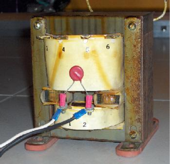
To the right is a picture of a FR. The bottom is the primary of 230V (connection 1-2). The top is the secondary of 50V with connection 3-6 (there are also some other connections to the same winding with lower voltage). This secondary has very thick wire, so good for high resonant current. There is an auxiliary winding (white small wires at the back), but not needed for our purposes. See the magnetic shunt between the windings.
FRs tends to correct its own PF making up for input variations; can be lagging or leading depending on input voltage & loads. 1.618 winding ratio to primary in normal trafo, then resonate; amplification factor is x10, voltage doubled, amperage x phi. You need the metal laminate shunt. Some manufactures use 2xPhi and hi voltage capacitors under resonance to lower cost.
TV REPLICATION
Jinis started a replication: http://www.m-primus.com/www/de/data/tv/tv.html
The optimal input voltage for primary is the minimal self sustaining resonant constant; the energy required to overcome time energy decay e-(H/2L)T. This is the cut-off amplitude, below which resonance becomes entropic and shuts down. That potential will reflect back to line as power factor correction (VAR). This is typical ¼ of the rated voltage at the nominal frequency. The constant determines the impedance match required (ratio) as is variable on aspects as Q, ampere turn, core parameter, wire size, capacitor voltage & electret dielectric constant & others you will find as you go.
Due to the ferro-resonance effect, the voltage tendency is to go up as input goes down, and the acoustic physical noise increasing in the transformer (predictable) until it cuts off a certain point (resonance shuts down) as null wave is created.
Note that you can’t start resonance with this constant level of energy. That resonance needs to exist in the first place in order to go down in power to find this constant, so first start with higher level. So don’t use a resonant pulse to first start a circuit, as if there is no resonance you can never try to sustain a positive constant feedback as there is nothing being acquired to sustain it.
Once the constant is found, try to find the optimal C value for LC resonance. In ferro-resonance the idea is to hit the core fundamental frequency where the electron spin energy transfers to the core magnetic oscillation in where energy heat transfers from current flow as H=(IxI)Rt as crude simple equation to justify genesis transform (hi Q) resonant mode. You must find a capacitor value where at a natural frequency the core becomes in a hypersaturated state and squeals like a pig. So again, find the core fundamentals and make a hyper-Q LC configuration, and work on time compression and energy JOULE potentials. The transformer core in itself becomes a "crystal" with a basic audible acoustic manifest in its fundamental Hyper Q resonance. Calculate the best coil-capacitor relation to acquire hyper-saturated states in transformer cores, determining the best optimal frequency to acquire OU transformation states (RE at low voltage – compared to Tesla coil high voltage), where a node constant is provided to correct time decay drift and maintain a loop (... using 2 resonant jin-jang systems).
For your natural Q, you will find a decay constant relative to your system Q. The lower the decay constant the higher the OU potential on your transformer core natural resonance regions. Ampere turn, core and capacitor are determining factors in design. Read MRA papers as everything there applies to TV.
Radiant Energy and OverUnity |
Page 52 |
Make sure you are not hitting the harmonics, as this means you are exiting within the sideband and not exactly in the fundamental, so the beat creates harmonics in the upper regions. You may require a variable frequency source as to tune in exact fundamental (natural LC) frequency. Once you attain the transformer natural frequency you will need to find the cut off resonant sustaining point, watching for frequency drift compensation as you lower input voltage. Remember input voltage acts as virtual varactor tuning diode affecting the frequency fundamental; as the voltage is reduced the fundamental frequency drifts from centre. The tendency of the voltage is to self increase as the frequency increases also, in self driven oscillator (inverter).
Note that looping requires a positive regeneration constant within sharing circuits in multi vibrator mode.
You can extend this to solid state 3PH transformer, MEMA (Magnet-less Electro Magnetic Amplifier) concepts. The TV is essential to create the B phase EM required for operating any 3PH transformer in MEMA Mode.
The diode plug is for extracting usable potential using non reflecting power, splitting capacitance bridging the 2x2, and 4x4 designs. To get OU power extracted, its total C capacity in joules Cj/1.618 /1.618, then have main C and 2 diode plugged capacitors in parallel C to get a resonant power split without killing the resonance effect. This diode plug can self trigger using a resistor and switching diode with small cap .005 and 6.8 K variable adjust neon trigger. You can use a lamp dimmer SCR circuit alike, but tailored to switch on at C rest charge (self triggering).
Every engineer from classic physic school would say the power with PF=0 is not usable, but here’s how it gets. In RF at C node capacitor charge is maximal, so you have JOULE potential as pure DC in this capacitor. Recapitulate on past postings: PM generator magnet saturates shorted coil, where V = 0 and I = maximal at 0 point energy current node. At the peak the coil is OPENED and this POTENTIAL dumps into C were C is tailored to equal in pure resonance hyper Q value to get the full charge from L across a diode until I = 0 and C equals maximal Joule stored potential at 0 point energy transfer. The M field charging a coil in optimal core ampere turn to core mass relation hyper Q half shorted tank where pure L is taken to saturation in PURE current node to hyper Q state, where OU transform occurs, at field collapse and energy transfer to a capacitor the coil cools down transferring its magneto-thermal energy to C. All the RV and TV experiments are tailored to get the experimenter face to face with the REAL 0 point energy.
Let’s say you prepare a transformer where you can wind the turns you want with the wire you want, say multi stranded hi frequency RF wire 12, 8, 6 AWG and wire your core to a point the highest Q at a frequency where the natural core metal resonates "fundamental ferro-resonance in this case". Taking this to extreme Q and elevated resonant states with proper matching network and feedback, such a reactor becomes self sustaining, transferring Electron energy to the system core and coils becoming cold and superconductive if system becomes self incremental to a given point of maximal energy saturation and resonance balance.
That is the secret of MEG, VTA and Hendershot. The basic gain is 1.618 over isotropic (virtual dipole) X the core Q multiplication factor that is the ability to latch magnetically and gain energy from its Electro-atomic components. Like Tesla stated hundred years ago, all you need to create is a SINK were the energy flows and is transformed.
When feeding the primary with let’s say 50Hz and you notice that your secondary LC is resonating at 150Hz, then it resonates at the 3rd harmonic. So get variable frequency
inverter and feed it the 150CPS it needs.
3.3Homopolar transformer
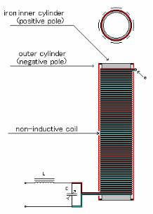
The Radiant energy can be transformed using special homopolar AC transformers, related to Gray Tubes. Homopolar transformers are no other thing than a cylinder inside a cylinder (long pipes of same mass coaxially placed one inside the other with no electrical contact as to use the Radiation RF, aka "Radiant Energy", to induce in the second external pipe an exact field of the first provided is matched to within a gamma, beta or delta RF matching to the secondary radiant energy circuit. More formulations needed for the AC Homopolar transformer, as distance is also critical proportional with the relative density match. At this point without a firm lab experience, they are useless until concepts are demonstrated in vitro adjusted to physical realm.
You could extract up to 20% of the radiant energy without
Radiant Energy and OverUnity |
Page 53 |
killing the action. The size guidelines for a homopolar transformer are that the inner pipe must equal the outer pipe mass (exact weight), the length must match the wavelength (acoustic sub-harmonic of 50/60CPS or any of its higher harmonics – do this by hitting them softly at the end, hanging as pipe bells; just cut piece but until you hit a basic or harmonic), aluminum is OK. The inner pipe must be the emitter, the outer pipe collector. This is the same as E-Gray tube but no spark gap outside pipe is tapped at ends to get power the pipes are isolated, inner pipe forms part of motor LC tapped at ends.
This is related to GENESIS files (A1 Genesis.zip) and Genesis coaxial coil (bifilar); use it in your charger or built coaxial caduceus. Correct and compensate time-energy component. It’s the only way to attain looping. Tuning is 10 times more bitchy than RV so I modified to hollow coaxial transformer ... it reduces Newman coil 1000 times with same effect "4KV hipot capable iso is needed" my reference is SEIKE from gravity R&D lab Japan. I got his book from WASS delta group in Seattle WS 1983 US R&D period. Use audio speaker alloy metal for the cores; flat Tesla LC coil sandwich in speaker end plates will do fine; watch for that METAL taste in mouth (field teleport of metal on EM field Aether stream).
In the pictures to the right you’ll find a Homopolar transformer: a pipe within a pipe of same weight; inside "tuned" pipe is source, external is receptor. EV Gray tube = Homopolar AC transformer. This is KEY to free energy, gives the basic TOOL to start - true R&D in HI power Radiant energy systems.
If we Delta match a series of phased LCs using homopolar AC transformers creating STAR loop, once initiated in Hi Q, the system never turns off, taking the self feeding power loop into a self destruct hypersaturation state creating energy singularity within the rotary elements. That was the thing missing from Seike formulations and his reverse atomic reactor design and theory. This is aplicable to Norman MRA as well to any hyper Q system.
The TV plug is used to EXTRACT partial energy from rotating STAR reactor using parralleling parasite LCs combined with the Homopolar RF transformers.
You can test this theory using AM and FM comercial radio final stages matching networks as well as Amateur Radio equipment.
Another kind of special transformer, seen often in radio-frequency circuits, is the air core trans-former. True to its name, an air core transformer has its windings wrapped around a non-magnetic form, usually a hollow tube of some material. The degree of coupling (mutual inductance) between windings in such a transformer is many times less than that of an equivalent iron-core transformer, but the undesirable characteristics of a ferromagnetic core (eddy current losses, hysteresis, saturation, etc.) are completely eliminated. It is in high-frequency applications that these effects of iron cores are most problematic.
3.4Reactor Core
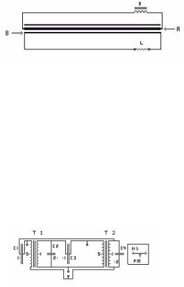
Take the following:
2x 120v/24v transformers C2/C4 twice as big as C1/C3
Top square between C3/T2 is a test point Bottom squares under C3 is the output Permanent magnet in the big square box
T1 T2 must be co-phased as to 24V coil be reverse inductor of the other, T1 excites T2, T2 excites T1. Jin-Yang circuit at resonance, one excites the other to OU saturation. As for the values I let to the user as the BASIC diagram explains all. Ferroxplana is best material Hi frequency gives the optimal gain.
Magnet is fixed at a distance to provide "Latching fuel" to any of the 2 transformers. This distance is determined by unit power level as magnet distance "TUNES" the circuit. Magnetic field feeds energy to the system, distance TUNES & Matches Magnetic field resonance to Unit resonance by proximity.
It can be made in solid state LCs (tuned transformers). You start with 3 cycles per second resonance in LC, split it to 1.5 Cycles using the 1.618 factor where you have a mass core delay of .181 CPS, so end product is 1.5CPS. This is MIXED to drive another core at 3 + 1.5 = 4.5CPS, where divided by 2 becomes 2.5 CPS at x 2 times interval, that is for every 6 cycles you inject back a LEADING 4.5 half cycle to rotary LC engine.
Radiant Energy and OverUnity |
Page 54 |
The system will self-loop with a feedback requirement of .002 the total power within the circuit. If done within 1 of the 81 universal octaves you have infinite energy to draw from universal waviton component (sinewave integral) – see cyclo-conversion.
When you touch a wire, you get frozen fingers, especially at 1.6 MHz operating frequency ... and yes this is same Original Hendershot principle, all you need is to get proper ratios, zap it, and it starts to generate self oscillation. Hendershot hid secret in a bunch of unnecessary crap, like the disclosure on the Buzzer and magnet was crap and dis-info. Hector decided to post it as the basics to generate RE are OUT.
In another variation, capacitors are eliminated from low L side but you need to calculate the LOOPBACK Q gain multiplication factor. Think of this as a self-fed looped stochastic gain dielectric element AMPLITRON.
This will switch the brains of many to "ON" states, just pass it on, you can use CAR Audio Amplifier toroids to do this. Finding the music that makes them sing. The magnet feeds power to the system as looped dual Class C linear amplifier.
As before Energy transfer comes from H=I²Rt within system cores. System cools down, can also overrun and BURN out in a GREEN flash as ferroxplana goes critical, atomically speaking (disintegrate) into hyperspace 4D. Usually unit levitates before this so DONT try to grab it as you can disintegrate with it, or loose body parts. In Hectors case, he shifts from dimension to dimension, glad they are parallel. So be careful what you do with this toy.
Unit creates extremely hi vitron Static charge great care recommended at looping (Use Fuses in LC loops). Vitrons result from electron decay to D4 states. Remember as C is attained mass becomes relativistic infinite, so electron seems like a LIGHT wave from a to b tensor in space, but as is static its state is as Vitron (Liquid light) The link to Ectoplasmic manifest.. of spirit world.. (Good place to keep your Stuff after you create it).
This unit uses 2 magnets with counter-balancing polarities, but first is to get device to work, building resonant stuff helps a lot. RV is a basic principle as power is amplified virtually. Same is done in the cores where one induces in the other. This is ELECTROMAGNUM, the power of the Gods, the secret of Atlantis. One coil can PUMP the other in rotating machinery. Think Resonance & OU, as KVARS fed into REACTOR by the MAGNETS … rotation self sustains. RV is an essential step to understand "Reactor Core" dynamics. The Generation of VIRTUAL ENERGY STATES is the key to the LOOPED REACTOR CORE, as is LC tendency to self regulate at saturation. Tuning is critical ... as in RV or TV PLUG.
In pure resonance a & c phases become self latching; compensate the BROADBANDING at latch and the system can also be looped. The solution is partial non-reflective non-entropic extraction;.that permits field regeneration and self sustaining
Data from 1999 series of Experiments - Transverter Secrets Revealed
480/220VAC Universal transformer design.
The circuit consists of 2 half LC tanks. A know the Radiant Energy flashover occurs at TURN ON, one capacitor charges to maximal resonant value then the cycle goes in opposed sinewave; as the other charges in resonant condition the first one is discharged in the second transformer with a nominal gain of 1.618 if properly tuned, this second circuit deplete C Voltage value as near to 0 Volts as SCR switches off at a minimal remanent voltage (minimal) before primary tank reverses sinewave to reload half LC and discharge the other loaded capacitor.
The discharge does not affect input tuning as it’s at opposed non-coupled relation this permits the full vector of the power components to be decoupled from the source (totally non-reflective) as to permit a PERFECT resonant tune of LC as to charge capacitor in RF radiant operation mode.
Now you have the BASIC and simple design of the looped TV circuit, just be very careful with it; use at minimal power and follow safety common sense.
For basic triggering you can use multi-vibrator opto-isolated mode a simple switching diode set up to trigger the opposed capacitor when charged, input AC regulates the timing, LOAD regulates the discharge time so overall time must be shorter (lower impedance) to increase frequency (shorter pulse) (shorter discharge time) as to reduce capacitor Voltage value to near 0.
Radiant Energy and OverUnity |
Page 55 |
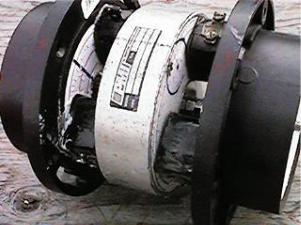
3.5Kone pulse motor
Doug Konzen has built several axial pulse motors with various numbers of stator coils, and magnets in the rotors. The picture to the right is a simple "axial RV" with 2 n-s magnets in rotor, and 3 stator coils on each side (© Doug Konzen).
PM motors pulsed 3 Phase are OU at specific frequencies and rotation speeds.
In AXIAL motors there is always a 90° approach to the pole, call it "sidewinder approach" (like the snake), its just perspective relative as how you see the 3d construct and the way M field interacts, but the same LAWS apply to all types of rotary machines. It’s just some are more efficient using force vectors and fields than others.
One good advice when dealing with pulse motors: forget all kinds of screws and bolts. You will see the difference in recovered back-EMF when you will use proper laminated core. So go to auto-junkyard and get some old ignition coils. From these you can get good impulse-cores and even some fat windings and HV windings too.
When tests were done with an old Bedini-motor and bifilar coil, with 8mm bolt as a core, the back-emf had to be collected both from the drive coil and from the pickup coil and add them up to get the same charge in the same cap during the same time interval. But when using proper laminated core, one could tap the back-emf from only the recovery winding or from the drive
winding and even better power level was reached in the storage cap during the same time interval. So the laminated core helps a lot. Also in plain bolt or screw there will be induced eddy currents by the collapsing magnetic field and you will lose energy anyway (eddy current loss).
Doug (aka Kone) build a big motor-gen, called the 363 since it has 3 coils on each side of a rotor of 6 coil positions (alternating N-S). There are actually 12 magnets total, with the 6 on each side separated by black plastic plate in between; this way the magnets hold themselves together strongly and wont pull out from the rotor since they would have to rip apart the black plate between them to get them out. He is firing repulsive-only 3 coils of the 6, 2 on one side, and just one on the other, and then firing the remaining 3 coils, (also two on one side, one on the other), rather than firing just two facing coils (normal) or all three at once on one side. "Splitting up" the coils being fired like this gives more power it seems to me testing it out right now...
It is found that most power from a single pulse comes form the stator coil being IN BETWEEN the N-S magnets, so that the coil reacts to BOTH magnets, both pushing and pulling the rotor in the same direction, since they are N and S...(let the magnets do the work Bill Muller would say). It is advised to try to resonate at HI Q your coils at 27, 30, 33 cycles per second in triangle 3 X 3 one half pulse feeds each one other half pulse feeds other 3 (see section on cyclo-conversion).
Kone also wired up a motor in attractive mode instead of repulsive mode, which had the best results with the FWBR AC legs across the "switch only". Now testing in attractive mode (more shaft power this way too it seems), the FWBR AC legs worked the very best with them across BOTH the motor coils and switch for some reason, so knowing this, he came up with this new "split" recovery scheme, the purpose is to add extra power via an extra power stroke that is supplied with its juice through the recovery circuit of the backemf/recoil, with minimal or no extra draw happening when the extra coils fire and make for more "free" (recycled at least) speed and power.
Kone’s idea is simple but great: at HI impedance the coil is attractor to MAJOR force, minor force takes energy from MAYOR one (MAGNET) as VOLTAGE is greater in coil, amperage reverses to battery charging it. Proportion tuning it is the secret (1.618 ratio), energy is obtained from the Magnetic field, the field captures what it needs from K ambient electron & thermal heat, Rotor nnn magnets becomes a 400 year long tripleflux monopolar energizer battery. Electric Wankel engine in mechanical terms (runs and runs and runs!).
Another thing is that the "vectoring" (diodes/fwbr) should/could be done at the SWITCHING (especially if this is what blows up like NW was saying)
Put the AC legs of your FWBR across the switch - the DC side into capacitor, and switch during OFF-time of primary this capacitor with DPDT switch into resistance to control it (your pre determined load)- 2nd switch at AC leg flips ON about halfway or 3/4 through primary pulse (now won’t lug extra current draw) and then stays ON while primary turns off (catching recoil power which blows everything up usually) this 2nd switch then
Radiant Energy and OverUnity |
Page 56 |
stays ON for a bit more, now catching the back emf....then turns off - cycle starts again with primary pulses only ON at first, then 3rd AC leg switch ON, then only 2nd switch ON etc…
Here is the scheme explained of a 2 vs 3 motor (see picture to the right). Motorcoils A and B are in parallel, and the 3 rotor magnets slide between these two...on the opposite side of the motor are two more facing-coils, C and D, (look at picture) which also the 3 rotor magnets slide through too...so the experiment now is that these two coils (C and D) are getting fed with the backemf/recoil collected from coils A and B when A and B together fire in parallel for the "main" (primary) motor-pulse...
So here is the best recovery scheme he could come up with to add extra power stroke with back emf/recoil collected with FWBRs on this particular 2vs3 axial (4 coil) motor:
Motorcoils A and B are in parallel and switched on-off to run motor. AClegs over SwitchFWBR#1 DC out goes into Cap#1
AClegs over MotorcoilFWBR#2 DC out goes into Cap#2
Cap#1 fires single coil C via switch for motor effect at proper timing
Cap#2 fires single coil D via same switch at same time for more motor effect...
The advantage of this split-idea is that the impedance of a single coil is 1/2 less than two of those same "primary" motorcoils in parallel, and so the backemf-recoil energy collected and then discharged from the cap gets to travel through a coil of 1/2 resistance as the two main motor coils in parallel have...so the motor doesn’t bog down with extra amps at all or just slightly when the "secondary" coils (C an D) fire and give extra speed and power..next step is to loop the backemf/recoil from C and D coils back to the original A and B coils and pull the plug and see if it will selfrun....
Definitely it will work well Synchronized, will do also as a rectifier, like the old type Synchronous X ray machine rectifiers an "H" cross switch HV non contact commutator switching the alternations into ++ -- poles. (Good for diode substitute in case of Nuclear EMP attack; those having the Know how will have a chance to survive the IC and transistor & diode fry out. Have a good stock of transformers & tubes. RV alternator can stand to nuclear EMP and survive it (not so 99% of standard generators which will burn and fry). As things go, point of no return is getting near, just try to prepare.).
For the axial RV in AC, the magnets ride a rotating wave like the OVAL (alike vector phasors of a Wankel engine), the magnets being pushed pulled along the wave. If a resonant condition is attained where the magnet can correct VOLTAGE loss as a POWER FACTOR figure, the device will run itself with pure magnetic wave modulation as a ROTARY MEG. A smaller series coil can offset feed the other forward coil in an endless loop (see reactor core for reference). Check MEG design; not like MEG forward reverse side to side swing, but like a wave circling inside a circle. A true rotary self amplification 3x3 rotary magnetic amplifier RMAMEG where the ROTARY wave self amplifies with the rotating magnet effect within the cores. Call it "Magnetic power factor correction".
The system will try to detune as rotor recedes in negative time, but the next coil will acquire the field in attraction mode, where the FIELD from the magnet regausses it porting energy to core & coils.
Theoretically the system will generate negative "G" as it acquires energy from time curve. Relative to us time will slow down inside the field as it acquires energy. To do this great insight and knowledge is required. Glad the Gravity-time corroboration came out in scientific circles, as now it can explain better where the energy comes from in such looped systems and how the anomaly is created. As soon as a relation to gravitic spiral flux toward equator will be related to POLAR (Magnetic) FLUX & the Jets flowing from BLACK HOLE poles AETHER, existence can no longer be denied and its role in universal energy transform, ALL MATTER is transformed to AETHER flux that is EJECTED at POLE ENDS toward LOCAL ovoid thorus in space time galactic string.
Radiant Energy and OverUnity |
Page 57 |
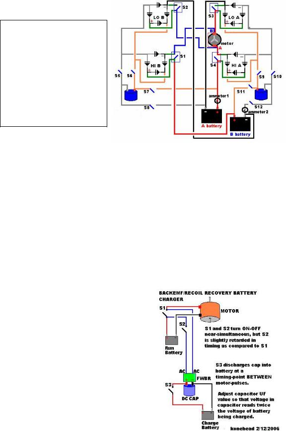
Here is another circuit diagram of a pulsemotor. It describes how the switching sends in current one way through the motor and in the other way (info
between brackets).
Simultaneous timed switches S1-S2 (S3S4) send current into motor through side B (A).
FWBR with AC legs across both switches S1-S2 (S3-S4) collects BEMF and fills cap through simultaneous switches S5-S6 (S9-S10).
Simultaneous switches S7-S8 (S11-S12) discharge cap into battery A (B) to charge.
Switches S5-S6 (S9-S10) fill the cap between the motor pulses.
Switches S7-S8 (S11-S12) discharge the cap between switches S5-S6 (S9-S10) and also between the motor pulses.
This circuit works the same as the TRANSVERTER circuit. As the capacitor
is charged in the NO LOAD condition it can RESPOND TO THE BEST resonant Q curve (in plain English: a specific FARAD value will give you maximal POWER from the coil discharge). As the switches maintain this capacitor independent from the battery, LOADING DOES NOT DETUNE the recovery circuit (transverter design). You go a step further using an INDEPENDENT battery as to get a blank spacing to permit the CAPACITOR to be discharged in an UNLOADED battery using otherwise loss return as an advantage.
To simplify it, use 2 transistors positively biased to fire into each other battery on the blanking space, or to charge capacitors and fire it on opposed + LOAD as assistive current boost. If you keep the meters above 0 + you have OU and your battery will never run out (quite the same as Gray did but at a MUCH lower voltage).
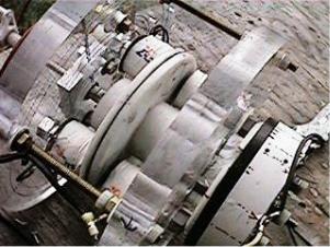
Definitely you need a 3 phase 230/460V motor with a Nb permanent magnet rotor N-S "2 poles" for a 3600 RPM motor (1800RPM motor requires 4 pole rotor - more expensive and complex). The recovery can be done with dual triplefluxed 6 bridged recovery plug system. A synchronous motor can be used for your preliminary experiments (PM ROTOR), as is it simpler to built a rotor for a 3PH motor than to built current pulse motor design from scratch (over 3HP).
You can use a disk to fire optical switches to control 6 independent SSR relays and use up to 127VDC dual bank batteries.
Kone©s motor is showing OU, partly because of the spacing of the magnets and the coils are such to have overlapping magnetic fields which is partly canceling the Lenz effect. This is similar to the 3PH oval shaped field rotating the 2 rotor poles at 120 the 3 to 2 ratio rotor stator coil relation.
The Lenz cancelling effect largely depends on spacing and field intensity. The worst sin is to over-saturate, it creates drag.
Here is Kone’s the ultimate BEMF recovery circuit for a pulsing motor coil. If you want AC, double this circuit up and make it go both ways.
If you have a 120V inverter firing alternating-polarity 120V DC pulses (now AC) then do that same recovery "over" the 120V switches and recover the BEMF those inverterswitches create, and pop it into cap, and knock cap into battery, BETWEEN the times those 120V switches fire. This way whenever the battery gets charged with a pulse, it doesn’t reflect back as additional draw to system, and so battery charging becomes "free".
Radiant Energy and OverUnity |
Page 58 |
3.6One-wire bulb - Brian Prater (Cavetronics Labs R&D)
The one wire bulb works on the concept of magnetic reconnection.
Magnetic reconnection is the process whereby magnetic field lines from different magnetic domains are spliced to one another, changing the overall topology of a magnetic field. It is a violation of an approximate conservation law in plasma physics, and can concentrate mechanical or magnetic energy in both space and time. Solar flares, the largest explosions in the solar system, are caused by reconnection of large systems of magnetic flux on the Sun, releasing in minutes energy that is stored in the magnetic field over a period of weeks to years. Magnetic reconnection in Earth©s magnetosphere is responsible for the aurora, and it is important to the science of controlled nuclear fusion because it is one mechanism preventing magnetic confinement of the fusion fuel.
In an electrically conductive fluid or plasma, magnetic field lines are grouped into ©domains©- bundles of field lines that connect from a particular place to another particular place, and that are topologically distinct from other field lines nearby. This topology is approximately preserved even when the magnetic field itself is strongly distorted by the presence of variable currents or motion of magnetic sources, because effects that might otherwise change the magnetic topology instead induce eddy currents in the plasma; the eddy currents have the effect of canceling out the topological change.
See http://farside.ph.utexas.edu/teaching/em/lectures/node84.html for an explanation on magnetic energy.
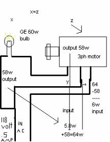
The diagram to the right gives an overview of concept and wiring.
The system uses 64 W from the line input, running the motor and light, the light being 58 W. The motor running at 1725 RPM without a light uses 58 W, where the light uses the 58 W that the motor has past off to the light bulb, matching the current. So we get 116W out version 64W in, as such there is about 52 W free.
The input is about 118 VAC single phase. At that voltage the light will use about 58 W (same as the motor). Now when looking at the voltage coming off the motor without a light as a load, it reads 92 V no load. Now when the motor output is loaded, it rises to 109 V and the light is lit up. So a rise of about 17 V.on the output of the motor.
Specific: 63.67 W-in - 42.45 W-out = 21.22 x 2 = 42.45 42.45 - 63.67 = -21.22 (+- 42.45 bandwidth) 106.12 W-out (63.67+42.45) - 42.45 = 63.67 W-used
= 106.12 total W-out / 63.675 total W-in = 1.667:1 gain
This motor is started with a smaller motor, as there are currently no run or start caps on the system.
The remarkable fact is that the light once lit, stays lit after you switch open one of its input lines, as to be lit by "one wire", costing just 5.8W for the 58W of energy used (not to account the other 58W running the motor). So the light burns on 58 watts one wire, and in fact uses the same amount of energy, switched on or off… "one wire or both wires" cost the same energy. (the light resistance is around 174-280 Ohms while lit). Node-anti-node, wherever you are at it you get it with one wire.
You can run some DC caps (e.g. 8900µF 250VDC) off where the light is hooked up, through a FWBR. You can then get 89 V at 0.5 A for free while running the light and motor.
Total input = 64 W; total output = 158+ W; 158/64= 2.46875 gain
Radiant Energy and OverUnity |
Page 59 |
Harmonic Series Expansion for Prediction of Over-unity Systems (drafted by Jason Owens)
Pf = s γPni n=1
s = # of collectors Pi = power input Pf = power output
γ = loss factor
|
s |
P |
= Pf |
|
Theoretical Max Efficiency Lim |
i |
|||
γ n |
||||
|
s→∞ n=1 |
|
||
System Efficiency |
ε = (Pf / Pi) x 100 |
|
||
Excess energy |
= Pf - Pi |
|
|
|
Loss factor calculation |
γ = 100 / (100 - %loss) |
|||
OU applet http://www.cco.caltech.edu/~phys1/java/phys1/lrc/index.html
This Java applet is intended to show you how a system of a R, C and L react with one another in a system. Use this to see the scope shot.
Use an Angular frequency of 23 radians/second, Voltage = 65V, L = 58µH, R = 4 Ohm, C = 7µF. This will show you the waveform a lot better on the motors and you will see how it reads "over current", but still matches the wave form. Brian knows from his 1/6 HP motor that the "over current" is 3.6-4.2 V
(over current = OU V !).
So let’s say we have this volts over; and add it back to the system, let’s say it’s about 26 to 32 volt (average 29V): 65 - 29 = 36 volts less input.
Let’s see how close it is if we do the 65V - 46.08% = 35.048V – 29V we get back = 6.048V x 2 (input line)=12.096 "tensor volts" or 120.96 line volts.
Now 120.96 line volts - 12.096 = 108.864V; see how close this is to Brian’s 109V on the one-wire bulb setup.
Say we have 108.864 / 2=54.432 W or V input from the motor and from the line-in power, and add the 54.432 plus the extra 4.2V, and we have about 58.632V or W; if we add both up 58.632W + 54.432W = 113.064V. 113.064V - 4.2 = 108.864V - right on the money...
Hector: Take in account Time, phase relation & phasor – within the following formulas:
((V1+V2+V3)/3) x ((I1+I2+I3)/3) x 1.732 x PF = Watts (circulation 3PH) A, B, C phases
Where AC input 1PH is (V x I) x PF = Watts => System is OU as is!
Phasors A=0 (line), B=120, C = 240, where A=0=360 (virtual relative).
So B must lead A by 120°, where the relative self induction sets B & C 120° 240° apart by means of C that provides the leading VAR power to the rotary 3PH engine. VARs runs the EMA effect. The 3PH polar field is rotary triangle ‘egg’ shape, where relative max torque to the rotor 2 poles is at 90° angle (relative).
The rest is resonance and its transformation engine potential using the ZPE on this engine type nodes.
Electron resonance
The nodes are points of concentration of electrons and vacuum of electrons; they can be made as resonant on multi harmonics along a conductor alike the light bright and dark spots that form along 8 ft long FL tubes.
Like in TV setup, first is to attain resonance then lower the circuit power or open the series circuit to attain linear open loop one. If one attains magneto-nuclear resonance from the ambient heat, you can get looped OU from even a resonating kitchen sink!
By resonating the electron field, you can get permanent wireless fixtures. Get Shuman frequency as a sample to resonate to it, then feed on one of the 1.3 to 1.8 MHz electron harmonics within the Shuman Hyperwave and you get all the free energy you want.
This is like resonating electrons in a light bulb filament within an OPEN dipole; ideal will be to place other open bulbs with independent switches and close and open each independently to see if they remain atomically resonant within the RV LC influence. If they do, you got something bigger going than you may think.
Pure electron resonance of the filament with a low frequency exciter radiant energy field. This is like a wet finger stroking a grass cup and generating ultrasonic waves. RV RF AC excites the bulb atoms to oscillate at
Radiant Energy and OverUnity |
Page 60 |