

Phedotikov / 1 / FreeEnergy_27.01.08 / Механические / Генератор Ротоверт Valeralap / RE-OU-v6_1
.pdfMicro-energetic cyclo-conversion
As mentioned before, the importance is to saturate the core and let it decay with its added ambient energy component into the power recovery circuit (Ringing); OU energy “one shot” Cycloconverter. Review phasing, once a coil is taken to saturation, there is no need to discharge the whole capacitor into it (ping it to saturation cut off). In a cycloconverter, one frequency excites it, another extracts the energy (the "short" excites the “long”).
In order for looping any resonant OU system, the Hyper modulated signal from Super signal must be tapped from the natural Universal SINE integral energy component, which is 3Hz. It’s taped using 1.618 frequency incremental step up and relative Q from 8 transformation elements, the first FEEDBACK Q relation is based in this ratio. (.215 .021 .002 values in octaves can range from 1 to 81). 3,6,9 (the MICRO relates to the MACRO) remember a lower signal can arise to a sequential creation of higher energy ones; like the Transformer ferroresonance experiment recording showed.
In another way, I am telling that RV can be directly looped by dividing one alternator frequency segment in 2 (60/2 =30), and mix that f to obtain 90 (90CPS/ 3=30 -- 30/10=3) from other segments using filter mixer array. The sub-harmonic of sine integral looping SINEWAVE superwave component is 3 cycles per second; unit loops and de-loops OU non-OU in this frequency. In a Universal Inverse Reactive Motor-Generator such a signal is fed BACK to primemover at .621 ratio of alternator voltage level (in this case 215VAC x.621 = 133.515VAC) at 90CPS were slip of squirrel cage reduces to 73 CPS maintaining a TENSOR of RESISTANCE against ACCELERATION (negative reverse energy and POSITIVE forward induction Valance - opposed pairs).
Unvalanced phases create the hyperwave. The unit tunes & detunes as a low CPS signal, hypermodulating the first from 0 to max. Average your capacitor values across all phases to lower this effect. In LOOPING this effect is NORMAL, because once your source is charged system goes under OU, it discharges then goes OU again in a slow long sine wave. This is what happened in Kone looped motor OU – non-OU – OU – non-OU. In any incremental tuned amplifier there is this tendency to detune and die as it overdrives and cuts off, its one of the priority listed bitch thing to understand in tuning in a looped system you have this cycling and its normal. If you maintain LOADING, you can regulate TUNE to any sweet spot you want. Best sample is to put DIODE bridge in LC and hook output to a car starter motor. As system starts motor is seen as a short, as motor accelerates resistance & impedance increases, LC power will die motor will stop, as it stops again is seen as a short and it will power on again. But if you PRONY break it you can maintain LOAD at a GIVEN standing wave were POWER will be sustained. In extracting power from ANY OU system this is VITAL to understand as HOW power loading can tune or detune a system. The In vitro experimentation is the TEXT book needed to understand this, else theory will take 300 years to learn. I don’t think any of us here have that much time to waste.
The typical slip of a squirrel cage motor in STANDARD use is between 1 and 4% depending of the load. But in RV looping, time becomes relative as f = V (frequency = velocity). Time (t) becomes a variable within RF rotary field. This is way advanced, but as more experiments are done to apply radiant energy this will be understood. The capacitors will cut off over-acceleration if tailored to stress non-OU to over OU. In PM just be careful with direct looping, as it will ping in incremental upper harmonics and pieces will fly up in the air and end as a burning piece of crap in floor (remember pulleys (low drag ones) can substitute cycloconversion).
Tuning definitely at this stage is "ultra bitchy", but with 18 basic ways to do it can’t be missed. Just remember load determines LC tuning in alternator, acceleration detunes LC, so its self-regulating angle of ROTATION frequency "LOADED". Primemover PF must be near unity 1, but alternator needs to be ‘wasted’ (PF=0), leading far over primemover rotation.
Try to resonate at HI Q your coils at 27, 30, 33 cycles per second in triangle 3x3 (star of David) one half pulse feeds each one other half pulse feeds other 3. The relation is to create a wave within a wave to tap 3Hz Universal Sinewave integral. Base frequency is 90Hz that means HALF pulse at HALF the time. Superwave WAVITON integration to fundamental frequency input within 3 phases ... (natural Cyclo-conversion and frequency integration) Stochastic frequency mixing..
On a scope you see a semi-rectified feedback with an overlapping mother lode at 3 CPS that will take your motor way OU. It will be difficult to tune each COIL, but the frequency relation (n-constant) is what is important in this case for 90/3 base = 30, where (n) is 3. Even if the frequency changes, (n) is .6666 x (base). A frequency creates another of stronger magnitude than the first, but is as it were a HOLOGRAM within the rotary engine.
ABC triangle (3) with ABC second inverted triangle (3) and sequence as explained in any octave from 1 to 81. It’s high-level order technology. Don’t expect to understand it if you don’t do the lab. It’s Energy Hologram forming. 3 basic colours, interrelate to form 6; 6 + 3 = 9; 1,4,8,8,5,7 1.42857 .142857 The micro relates to the macro and the macro relates to the micro.
Radiant Energy and OverUnity |
Page 41 |
RV is the Star of David in your hands you need the BASE or the ARK of the covenant to unleash it power upon the world. Study the solar rays as they pass a triangular prism: 3 rods at its tips, run it in 3 phases at the frequency of light. What do you get? Up-convert and down-convert to it ... the universal "hologram".
Since all power is interrelated, you can use the system as wireless Internet by pumping a broadbanded superimposed signal in a triangular crystal lattice and use a NEUTRON frequency signal as super-modulation to 3 CPS one (Atomic stochastic amplification). 100,000 times more powerful than nuclear energy as used standard.
Harmonics are created within non-linear components, where in the RV/TV we ©only©have Ls & Cs? But harmonics can be natural fundamental in FORCED electrical fundamental within a transformer or device. The Forced Fundamental, say 50 CPS, does not necessarily needs to be the NATURAL fundamental of a transformer. A transformer frequency range can be in a set of natural frequency fundamental to its own construction, say 47 to 570CPS.
Reverse induction creates BASIC 3 phase in fundamental frequency region and tends to be table as is determined by speed the LC bandwidth determines the Range of Q within a speed variable in reverse induction the ROTOR is a NEGATIVE RESISTOR providing ENERGY to LC, as to keep oscillations at hi energy level. In solid state the highest Q the lower the energy required in input to sustain it. The same applies to rotary engine.
Indian secret "Lingam power" unveiled. Now you all know even if its "encrypted" is symbolically designed to activate "hidden knowledge" already contained in HUMAN GENETIC code for this work; idea will pop to mind like a shotgun blast " just retain it " and apply.
To run 3 brains in 3 phases (red for heart chakra, blue for right lung upper chakra and yellow for pineal gland). R L & central NS will run in 3 phases rotation upon vectorizing mindwaves in 3CPS. Blue cachina stargate opens, and I reveal my face…
Coil-Core-RF-DC repeat
Pure "L": idea is to charge coil and core (if any) to saturation, being the collapse discharge the OU producing element.
Pure "LC": idea is to charge a capacitor to max potential within a resonant circuit with the lowest power usage to primemover. The RV alternator does already OU, using reverse resonant induction. L being impedance matched to C as to attain EMA gain from M field.
PM induction RV & Muller RV: here power factor & resonance intermix, where PM "M field" saturates a COIL & core as to cause a charge resulting in OU potential, as it gains power from M field "EMA" and ZPE "C" components. JM charger, RV & transverter play big issue here ... (LC).
The current problem is attaining the PM induced OU states and understanding how to transfer this power as a vector to a battery. Check looped RV schematic.
If by sample 200V at 10A, this is the same as 20V at 100A at alternator end, capacitance and impedance responding to same proportion but increasing Q to the hilt x10 Q extreme "OU" states ... battery and its charge becomes a VARACTOR diode in series with this LC, battery power is determined by amperes-in amperes-out within a virtual load, inverter becomes R in parallel with source that becomes added to series LC vector source the RV output becomes a current vector within the R component where the battery becomes a varactor in a negative resistor state where such becomes C and L as reverse induction is attained, RV output becomes virtual higher VOLTAGE battery to LOAD where current transfers from lower state in a current reversal to higher state one, voltage differential causes reversed voltage to reverse current to lower power region into battery.. R becomes a virtual shunt regulator, in this case the inverter.
In the RV schematic the symbol of transformers and diodes from the RV alternator represent the downconversion of voltage and increase of current and this is done using RF engineering rules. Those rules are simpler if using a Muller generator, but issues are the same the sum of vectored DC must relate to battery parameter and your inverter specifics and within a range of 10 to 15 volts DC as to play safe, current & volt ampere is were the magic is, the battery is a VARACTOR LOAD relative to the SOURCE impedance. To maintain OU transform from ZERO point, the RESONANCE TENSOR must be maintained within all circuit elements, so it’s time to get an inverter, power up the RV from a DC battery and start vectoring your generator output into the battery and load stream.
Radiant Energy and OverUnity |
Page 42 |
As a simple shunt it’s all that is needed to demonstrate OU (current charging battery) and a voltmeter to monitor voltage 12.7 optimal ... a series of loads must be provided to prevent overcharge and create the hyperwave OU- non-OU HI-LOW wave cycles - normal to a well tuned system. Regulating load can be at any stage. The principle is quite well demonstrated, however the issue is to transfer it to a working physical model within closed loop and mitigate the impedance mismatch problems.
Tips: coil voltage as DC must be greater than battery ...real load must be battery not a resistor. The real POWER then becomes voltage differential of source relative to battery multiplied by the amperage ...(charge) "OU". The re-circulating power is imaginary "virtual" power within a local singularity created by the device as a whole.
Tesla spoke of tuning the load and source. A shorted out coil trashes whatever impedance matching relation it has with the M field. M field, coil and capacitor tuned at a given speed and a given frequency with a properly designed core, coil, capacitor, relation ... are key to OU. Shorting is OK to test Lenz drag. RV idea is to optimize energy output, not prony brake it to death.
The real design challenge is to drive current back to a battery and in DC its POWER factor is measured in REVERSE voltage relation. Say battery 12.7 VDC, source 13.7 VDC, differential is 1VDC. In a charge relation the reverse resistance is the power determining aspect, say as a sample 1 Ohm, then the power charging the battery is 1V x 1Ohm x 1V = 1W true relative power transfer ratio.
So we have as a tensor (DC) equivalent of Phasor (AC) (power factor) relative rotation angle to co-phased element "synchronous".
So as we may equate battery resistance + load resistance in amps at a given VOLTAGE drop, lets say 12.7VDC At 10A that required to BALANCE a tensor of 10A, so we must calculate voltage required to valance such where generator Source voltage power must be higher than battery as to reduce draw and reverse charge to it. The impedance must then be lower than the battery one as to transfer current to load and reverse to battery (same formula above) where the generator overcomes power requirements feeding a reversed power factor vector to the battery. DC is nothing more than an extremely long sinewave and RF rules also apply to it but as pure standing waves. Understand that and looping is within grasp.
Something very interesting that everyone should understand is that you can’t just do resonance formulas only to find the right resistance and capacitor size for the particular inductance of a particular coil - the factor that can only be seen by actual bench-testing, is what the motor goes up in draw as the coil is loaded. As example, if I brought the cap size from 47uf down to 22uf, now I get more power-out, but this change also makes the AC motor draw increase.
The load acts as a VARACTOR diode & only a few are qualified to deal with those theoretic aspects. In a pulse generator, that means using ONE pole, idea is to charge the coil with the PM and using the M field collapse as power source being non reflective to mechanical power source. R load will a variable determining the time T and current level discharge of L, L will be affected by C internal interwinding capacitance and OTHER also self changing parameters. The 4rt dimension is the PROJECTION of all the parameters to an unified set of final values determined by all the components. The MODEL testing is the only WAY now possible to perceive this aspects until the proper formulations can be included in electrical computer simulations .
Now anyone can be able to SEE where OU is lost and why alternators and generator designs are flawed and the need to change engineering concepts into a more broadbanded region were RF knowledge becomes vital to be able to integrate and interlace the INTERRELATED parameters affecting the way generators and motors work. RV is a Toy to discover interesting new things.
Further considerations
The concept of RV alternator is not new, as to use any motor as a generator putting a capacitor in any ABC phases, but using RESONANCE LRC concept in series is new and is Hector’s public domain copyright. RV was meant as a power source for the now free domain Ecklin-Brown generator (1978 patent expired).
Before building a RV, one could think of it as just a motor configured to run more efficiently with capacitors. But there is more here than just that. It is impedance matching (the famous dipole theory taken to practical application, semi-resonant principles are interacting here with the virtual creation of extra phases. All Seike’s Ultra-relativity formulations apply here on rotating magnetic fields.
RV is not important on its own, but what is important is that you learn how to make it WORK and use it as a tool (as the recovery circuits). Integrating RV knowledge to it is what will permit you to use these motors connected to an AC line & at higher intermediate POWER to attain replication of E-Gray concept & overunity.
As RV is taking solid ground, lets put the facts on the table:
Radiant Energy and OverUnity |
Page 43 |
∙Standard motor stators in motors are more efficient as HP goes up: 50% low power, to 98%+ hi power HP (http://www.reliance.com/prodserv/motgen/b2838.htm); Eff goes up as rotor mass goes up.
∙Baldor high eff motors: 100% eff at 10 HP; In RV mode and with PM rotors, they are OU.
∙The primemover is demonstrated: RV effect (rotoconversion)
∙The alternator is demonstrated: RF RADIANT ENERGY (Tesla, E.Gray, Keely, Hendershot, Bedini, Bearden, Newman, Wootan systems).
∙The RESONANCE is in OU RADIANT ENERGY levels within rotoverter alternator. Idea is to extract RADIANT ENERGY WITH NO LOADING to SOURCE.
Any motor can be run at RV mode, even single phase ones, but the reason this has not been discussed is that you cannot find 460VAC motors in single phase. A single-phase motor with start winding can be converted to RV, but requires much more capacitance making it more expensive. Its starting winding is at 45 , shading the main winding, which gives much less torque than the 3 phase one. The capacitor and phase angle create a “wedge” wave effect more acute than in 3PH, but requires greater control (step-down transformer or variac). Tesla biphase motors are better to use in one phase but no one manufactures them.
The RV equates TESLA COIL primary without the spark and massive hi voltages but with same RF "capacity" for pulse operation, RV reverse induction is similar to the finger in the wet glass cup trick except is done by electrically augmenting the signal instead of mechanical acoustic mean.
This link http://pirt.asu.edu/detail_3.asp?ID=811&offset=200 takes you to a series of acoustic resonance experiments that explain well what takes place in RV alternator insides. It’s an ELECTRICAL equivalent as acoustics LAWS apply to electric ones.
There is a big difference in standard ADD a phase and RV modes. RV modes can be attained in a one phase operation, but there are NO motors WIRED for 460Volts in single-phase mode. That is why I used 3 phase and at the same time attain more gain by the Capacitor extra phase generation. There is also a more convenient phase angle than in the standard starting winding of a single-phase motor.
In testing made way back using a 120/230/460 3ph generator, we replaced the exciter unit with a variable power supply feeding the ROTOR to magnetize it "no slip". We found the device lowered the power usage of the lab devices 40% as it corrected the POWER factor.
In RV mode, current in RV lines increased as we magnetized rotor but current decreased to utility lines…PF correction, magic word to hide OU & free energy so leave it there is PF. It is interesting to note it also corrects the PF of a battery, as if pulsed in gives pulsed back more power than what it used to move itself! Konzen is correcting the Power factor of his battery. Bedini and Newman is the same. MEG corrected the core PF… (Keep this as is another containing revealing answers - slightly encrypted but evident for smart eyes). Note that a Rotophase (http://home.earthlink.net/~ojmsmith/indexd.html) differs from RV mode in IMPEDANCE, voltage, current, operation & transformation theory.
Its energy savings potential can’t be overlooked for long, its a matter of time the engineering community starts looking to Rotoconversion modes and its applications, the magic words are cost effective, viable, durable, redundant, standard base design (off the shelve hardware) simple construct.
Best alternators you can built is taking DC pm motors and using the commutator as phases into - + diode multiphase bridge, mounting stator magnets into same ID pipe coupled to RV shaft as External gen rotor and using rotor fixed to shaft support as stator .... from each commutator segment same wire length is used into diode bridge .... Much more efficient than car alternator (more phases). Adds up as 15 phases uses 4 for brush contact means 375% more power performance as a generator if you diode rectify each one into outside PM rotor with internal brushless stator ...
I had no other choice than to give this the way I had done and without the dedication of people efforts to replicate the experiments it might just still be an useless paper posted as a curio in an internet page, so Humanity owns a debt of gratitude to those taking the first step, without you the RV potential might have remained unknown and I might already be dead. Sooner or later a motor manufacturer will take an eye on these systems and call us as to how to manufacture it to please the alternate energy community and industry.
On the other hand there is the tendency to over-engineer and prevent secondary use. All motors will be replaced by things you can never use. It is called “second use mitigation” and is currently on NSA priority R&D agenda. They started it with CAR alternators, engine and electronics, in computers with the ATX power supply configuration to prevent its use as a NORMAL bench power supply. Trace what happened to Synchronous Motor history, why they were removed from the market? The EV GRAY motor was constructible from any normal EM motor-generator, but it was OVER-engineered to a non-replicable piece of junk. 3PH motors had raised price 50% since RV disclosure; they are using HIGHER impedance in newer motors and lower Q cores to suppress RV effect. My advice buy all surplus you can as 5 HP motor now is $1300 USD
Radiant Energy and OverUnity |
Page 44 |
If a normal generator can be purchased with a 300% duty and 2KV high voltage certification, then there is no single reason why it can’t work with RADIANT energy pulsing as a MOTOR! The RV alternator replaces the EV Gray Dynamotor alternator and any EM or PM alternator can be used as EV GRAY PULSEMOTOR. Hector is linking the relation of RV to EV Gray work (Radiant Energy). The RV and Gray phenomena are the same thing. You built an RV; you can build EV GRAYS motor-generators also.
Converting Bedini to 3PH RV Mode: for RV Bedini mix, you require (sample) 3 coils in the stator per every 2 in the rotor, spaced at equal angle intervals (sample 120deg for 3 stator poles, for 6=60 deg for rotor, 2 poles 180 deg, 4 poles 90deg) then you can configure your coils either in delta or WYE. Pulse to emulate 3PH timing at A,B,C intervals, recover CEMP using simpler 3PH DIODE bridge … 3X the power out. Your cores may heat up so watch for burn outs (use transformer laminate if they do overheat). This will prove RV and Bedini are working under the same phenomena.
A motor operating under Smith patent will use the stated plate current all the time. The difference is that RV uses nearly no power as long as is not loaded, and acts as a transformer with de-rated HP (standard mode). Any MOTOR with core loses of down to 1% can work better than any Bedini coil. Any 3 PH motor in Hi impedance with a PM rotor can exceed Bedini motor power a hundredfold. A 3PH 230/460VAC 12 lead 10HP motor with PM rotor can exceed Newman motor (7,500 pound) tenfold, and cost 1/20 $$ to built.
Q& A of RV replication
Q: I am currently building a RV unit. I have 2 nearly identical motors, mechanically linked, both 3PH 5.5KW 2800 rpm. Motor unit is wired for 660 V, driven with 220 VAC.
A: Prime-mover must be driven with 165V for proper 52.1 Ohms impedance (minimal)
Q: Generator unit is wired for 380 V.
A: Q here is too low to attain hi gain, wire for 220 if possible & raise capacitance. Higher Q more gain less energy required from prime-mover to attain radiant energy at a given frequency and mass.
Q: Un-tuned, motor needs 600 watt for driving generator, while 4200 watt virtual power is generated in generator, single phase (not yet extracted, un-tuned).
A: You attained near resonance in Alternator "amplitron alike" very near RADIANT energy. Get a magnet near motors and compare different hand vive feeling; energy passes as RF and radiates out of housing in alternator while in prime mover this effect is minimal. Also approach the magnet to the wire lines in prime-mover and alternator. E-Gray tube uses this energy, requires use of "homopolar transformer" rods or grids for E Gray. Next step is to VECTOR this energy into different LOADS & experiment with it until the tuning and energy transform are understood. Applications from solar co-generation, dynamometer, dynamotor are easy attained for lab work and household use.
Q: How small is the window for correct cap values for creating an exact standing wave within 2x500W bulb?
A: That is why I specified KNOWN AMPERE LOAD were the USE of EXACT amperage is required, else thermal overrun will blast the bulb to bits or melt filament. If LC is 8A 263 V, use 2000W light bulb for 230 VAC then adjust cap for drift.
Q: I think, a big problem is the shift of filament resistance due to different lightning.
A: Yes, but can’t be exceeded given LC current if load is same or higher. This experiment demonstrates COLD electricity, as if done right filament will fall in current node of dipole resonance and voltage drop will be 24 to 19.8 VAC (easy operated underwater as Grey did). Do that with a normal 220 flashbulb and it will blast away with a big bang.
Q: I saw z.e.u.s. lamps and the simple negative inductor. Why and how does the teleportation take place in line to the inductor? It reminds me on Joe-cell principle. Are you able to explain this?
A: Aether flows in coil meridian toward centre "gravity flow". M field flows out from coil ENDS, this flow can carry phase dimensionally atoms from core into an energy loop, the higher the energy the more danger there is. There is an immediate metal taste in mouth when this happens as body WATER tends to trap dimensionally phase-shifted atoms. Gold, silver, titanium must be used in genesis type coils, or pure biologically compatible iron. In USDOE experiments they used titanium cores.
Back to RV, instant application is to run RV using frequency and pulse-length controlled inverter to synchronize asynchronous generators to lines in overspeed mode to supplement utility power. The advantage is if load is reduced RV demand in prime mover also reduces.
Radiant Energy and OverUnity |
Page 45 |
In solar energy this is a stumbling block under 5KW regions, but with RV mode run motors, Solar to asynchronous conversion can be attained under 1KW exceeding 75% eff. Using NORMAL state of art method that is impossible (under 30% eff) as in LOW impedance motors waste 90% to 98% of its energy with no loading!! In HI impedance motors use 1/10 to 1/20 the rated max load HP rating for RV operation
Using PM RV motor that can be taken to PF correction figures well in OU transform regions. 461W per HP over the standard 746W figure, being the rotor M field relation to line input M field impedance x 1.618 x Q core factor x PF.
Squirrel cage is a loss factor; any properly designed PM RV connected to a house will provide KVARS to it lowering utility power usage. You can call that "free energy" with an EM (variable) electrically exited rotor you can regulate power correction and amplification figures.
You definitely have a very useful tool in your hands now. Just be careful with the "looping" as it will take you to other realms of science. Energy savings applications are much safer for life & health. If you loop perfect, Cayce predicted cosmic energy may be used first in Europe unstopped by American suppression & greed.
Q: The magnetic field from bifilar coils is 0 in 3D-Space. What happens with atoms under this condition?
A: Light is measured as speed. But what happens if measured as frequency standing wave Reverse were M = MC²/(T/T). Matter reverses in time state to Light.
Q: And where is the connection between mind and the field, generated by RV?
A: As the frequency is increased toward LIGHT speed, matter becomes degaussed to the square and PK energy is amplified to the SQUARE also. That is why persons with no CENTER of gravity cannot travel in time space or exceed C to 4D or 5D states. Personally I resist 5D transposition, a normal person simply banishes into NONexistence due to lack of gravity centre.
Q: How do you know if the best run cap brings the motor coil to resonance at 60 Hz, 120 Hz, or 180 Hz? In other words, how can you be sure you are in resonance on the fundamental and not harmonic?
If you resonate on a harmonic, it will bog down and amperage will surge. If in 3 phases lower harmonic, it will slow RPM at basic coil harmonic frequency. If high harmonic, it will double the speed.
But in 3 phase motors it’s a NO as it acts as a filter as what you do is alter phase relation under semi-resonant condition. Harmonics require a shitload of Q, something RV only gets in very loaded conditions, but it acts like a filtered amplitron device, so harmonics again are a NO as they only exhibit as a phase shift modulation, nothing more. RV is quite stable in that sense.
Norman Wootan (Mon, 25 Feb 2002 – on Keelynet-rotoverter)
I built Hectors phase rotoverter with the following results: Motor is 3HP, 3 Phase, 60HZ, 1725 RPM, wired for operation on 480V. Motor free running, tuned to minimum current draw from 120V line input required 20mfd 370V oil filled cap resulting with a current draw of .66 amps @ 120VAC input. Motor loaded with belt drive step-up 6:1 ratio to drive a PMI disk PM, DC motor acting as a generator. (generator unloaded) required 30 mfd, 370V oil filled cap with a resulting current draw of .50 amps @ 120VAC input.
Now I loaded the DC generator with 160-watt incandescent lamp load. Since I have two independent systems here, one being driven with 120VAC line input and the other system a belt driven DC generator being loaded with pure resistive load. Here are the numbers: Motor was retuned for minimum current draw which required 45 mfd, 370V oil filled cap with a resulting current draw of .15 amps @ 120VAC input. The independent generator put out .75 amps @ 74 VDC into a resistive load. The only thing that needs to be looked at on the input side of the equation is the power factor of the AC input.
I need to to look at the current/ voltage phase relationship. I©m satisfied with the figures that I calculate which shows roughly 18 watts AC input with a DC output of 55.5 watts. What I find most interesting is the fact that the more load you put on the 3-phase motor the lower the input current draw and the motor gets colder. The belt driven DC generator gets quite hot after about 30 minutes of running time. Go figure it out. I believe there is a lot to be learned about revolving magnetic fields in 3 phase motors and tuning the output via capacitors. This experiment is so easy to do everyone should seriously look at this phenomenon. My next step is to document PF on input and improve the DC side of the circuit to provide more loading.
Go to this URL and carefully read how the RV really works: http://home.earthlink.net/~ojmsmith/indexd.html
Hector: You Forgot Otto does not use Hi impedance mode, Otto device loads standard currents on line (constant rated demand) load on no load to motor shaft. OU is lost as the free wheeling is lost to synchronous hysteresis Rotor cannot exceed synchronous speed unless compound winded to do so.
Radiant Energy and OverUnity |
Page 46 |
3.2Transverter
Overview of Operation
Standard AC transformers can be pulsed to OU transform states by taking them to resonance. The power within the LC ("radiant in nature") provides a source of imaginary potential within the shift of power factor non-linear reflected to the source. In pure LC the AMPERAGE reading is the important factor as in Radiant Energy this is measured in AMPERE LOAD, as in RESONANCE the "R" is antinode where the voltage value (in a perfect theoretical system) must be near 0 and amperage maximal.
Why is this system OU? Simple LC have a DECAY value in time, so the ONLY energy you need to supply is the one lost to DECAY as if system source where a negative inductor to LC (as is the case of RV alternator rotor; similar to a wet finger on a glass cup - cup decibel energy output exceeds finger input as glass molecules transform energy from their RESONANT STATE adding to input). Normal entropy decay is .618 of 1.618 as logarithmic time receding signal, so gain is also in atropic system of 1.618 where frequency increase in octaves may increase amplification by a factor of 3.141592 where the spiral resonant circular projection can be expressed in a 12,000 4d polygon structure (similar to double helix DNA structure – the reason the human system is OU by all definitions).
Remember logarithmic spirals orbital decay path is relative to gravity as signal decay or gain is relative to LC Q and parameters in a working ZPE system.
Surplus 3 PH transformers are good for these experiments, WYE-delta combinable 480/230/120VAC I/Os. Normal Universal transformers 480/360/240/120 I/O isolation 3KW 47-450-CPS are ok, but TUNING and a lot of work in vitro lab experience is needed to GET the idea WERE OU is and WHAT RADIANT ENERGY is all about. There is a lot that can be done with 3 phase transformers. A MAGNETOTRANSISTOR is just one of them. The transformer is superior to MEG as it does not need magnets to attain OU radiant energy states.
Try rotating it first, to enclose the field within the transformer core. Resonate the side coils, vectoring DC plug to the center coil, drive in 3PH rotation (A,B,C) to create "MEMA" magnet-less Electro Magnetic Amplifier. Splitting the transformer’s center-tap, feeding POSITIVE across winding and SWITCHING the negative using a reverse DIODE in the transistor to capture and feed back counter EMP as the transistor switches off. See schematic in PDF; just find the right frequency and pulse-length to make the ferroxplana sing a song! As in NEWMAN coil, BIG CORES have nice CEMF EMP.
The Side lodes: R/2 Ix2 where centre amperage B phase x 2 times. A,C phases current and A,B voltage is V = V/2 as A,B phases are 90° from centre C phase instead of 120 deg required in 3 phase relation; so being in phase relation is (V1+V2+V3/3)x 1.732 = VT in relation to V input (same applies to current-power relation). You need Q 12 to 15 to sustain rotation with near 0 field loss. Impedance is projected to infinity as fields open and goes widebanded with a projected M field out of the transformer (exteriorized field).
The solution is to co-phase A,B,C relation properly to create SELF impedance regulation within HI Q modes. Outside of the transformer this can become a POWER source as a SOLID EM AC EMF source if placed inside a coil ... short the coil, impedance decreases, and Q increases. Just we need to see the 4rth dimensional picture in 3Phases of the whole construct in a given space .. phasors field projections interactions, all the works ! going inside and out within that transformer.... Contain the rotation, increase the "Q" Resonance gain eff. goes up. (this gives also more ideas on the postings related to Sweet VTA Magnetic latching and Resonance; revisit also the MEG).
Loading the sides of 3PH transformers A,C phase exteriorizes and projects FIELD outside transformer. If another LOOP is used it becomes a magneto-transistor. Experimentation is the key to obtain these effects. 3PH transformers can be used as Scalar WAVE EW EMP weapon. Work also harmonics. One frequency rotates in one direction the other counter rotates within; this is little known in power dynamics but is key to many OU states related to Magneto-atomic resonance.
Maintain rotation, else EM field will leak out forming exterior projected field. This leaking is useful in other applications: put a coil outside the transformer and it will generate quite a good AC signal, as test to verify condition, this Broadbands LC as IMPEDANCE increases so Q goes down.
The trick is to Obtain HI Q at a given frequency, such resonance occurs. In your transformer case "ferroresonance", as in any circuit you must look for losses that reflect in lower Q and limit accumulative incremental resonance. Every transformer is Unique, not 2 are equal, as also no 2 capacitors are equal.
Once attained a given Resonant Frequency, the Exiting Pulse can be shortened; at a given point where ringback OU effect is noticed, core magnetics porting energy to system, the requirements become minimal as per 1 Watt
Radiant Energy and OverUnity |
Page 47 |
being able to maintain a HI Q kilowatt range resonance. The problem even a Clamp on Meter impedance detunes the LC, your BODY field changes the frequency as you get near it, MOON gravity Tidal force also detunes it. These aspects being very interesting to test in vitro as gravity influence is noticed under these conditions, Mass concentration becomes a Parameter in the operation of device.
For certain 3PH applications, 3 independent transformers are better as they are magnetically decoupled. The phase becomes more "malleable" to capacitor value influence. A triad Ultra looped system can be developed using SEIKE rotary transform theory (under resonance) self-inductive modes.
Bifilar inter-winding capacitance tends to correct power factor de-phasing from resonance, but the SCALAR TENSOR providing the STANDING wave is removed. Gray used AC homopolar principle to do such transform, as long Radiant state TENSOR is maintained such tensor will manifest OU with a corresponding thermal pump effect. Quantifiable by Delta t transform (Thermopile effect), it’s in reality simple but is LOST in the attempt to leave the Dual 0 states of resonance. POWER is not a "Unisex" force. The FORCES of the Universe are always manifested to fullest force when FEMALE & MALE forces interact "bipolar".
Good toy to play with is a 2x 75 KW 3PH used for MEMA experiments. We took it to resonance using a pulse driver driven with an AA 1.5 VDC volt battery where the 3W pulser developed a 10KW ringing within the core. Hector used Seike configuration Wye/Delta modes using pulses to maintain system rotary field ... 480/500VAC for Hi 208VAC delta low using 3x3 600VAC 22µF capacitor array, in a 75 KW 3PH hi efficiency ISO transformer (FCC grade). The ringing varied in decay, frequency voltage increase from 1 cycle 1/10 sec pulse to 10KC 800V PP cut off end signal. A Ping with incremental voltage and frequency decay within a rotary LC triple-flux array. Even in a valance capacity-impedance array, the system tendency is to rotate clockwise under 1 phase pulsing A,B,C selected inputs. A 1.5VDC battery can power a 3W LC Driver, a Pulser can drive Joules into a big transformer; Exiting core to GIVE energy from thermal region (OU).
Hidden somewhere Hector has the NASA rotary resonant transformer formulations, and they are nifty OU. All RF resonant coils are OU ... Stochastic resonance is the FIRST demonstration of OU.
If you listen to a Ferro-resonant transformer the core rings to the AC frequency at RESONANCE as electrical manifest into the mechanical ring frequency of the element being used as a core. This relation is considered UNWANTED noise, but for OU production like in VTA type latching you must put the Metglass to scream in agony on electron spin erotic delirium in order to attain certain energetic transfers from magneto atomic thermal regions to the electrical circuit ones (OU). If inverters TR cores were made to scream, they go OU but transistors & Fets usually fry as they are not designed for it (nor the circuits they are on).
You may need frequency and pulselenght adjusments in normal DC to DC H network inverters. The upconversion to Hi voltage is adjusted as to EXCITE the ferroxplana to OU states charging the capacitors under sinusoidal logaritmic standing wave. The H network fires the capacitor charge as also frequency and pulselenght adjust.
It goes “TUNG”. That "Tung" is not 50 or 60CPS, but 10 harmonics up 0.5-0.6KCPS. As 50 or 60CPS feed the transformer, the power line frequency echoes of the fundamental & harmonics interact forming WAVITONS within the core by core natural "cycloconversion" effect. Use an Equalizer Chart and see the so-called resonant PULSES are NOT in the fundamental frequency but in a multi octave broadbanded in hypermodulated Waves across equalizer frequency range.
As the transformer is in Extreme LOW Q and its fundamental RESONANCE is WAY up from the power line one. This is what must be compressed into a rotating Hi Q phased COHERENT signal to attain EASER modes in the core. If you compare such a chart to one from a PUMPED laser rod you will see the simile, they ENHANCE this effect to Amplify light. Why not enhance it to amplify electric current, and let it acquire energy from ambient by stochastic amplification.
In resonance capacitor charge becomes maximal discharging this POTENTIAL non-coupled to (not loading and detuning source is key. Idea is that M field logarithmically charges C upon influencing inductance and core (if any); logarithmic gain is 1.618 as defined, so its a 4 D projection 72° offset into "other plane" or I may say phase and virtual relative energy state. It must be tailored to occur in PM driven alternator .... to get a logarithmic gain into a given capacitor value from a 0 charge state (optimal) to make CEMF a linear forward vector (+ power factor) force. Verifiable easy with the postulated line of experiments being performed with RV-Muller Gen setup.
We have talked within the lines on this subject related to Easer modes: "seek the acoustic signature within LC resonance". "Ringing" as RV works is this state, it hums like a turbine (gravity and magnetism are not far apart).
Radiant Energy and OverUnity |
Page 48 |
If a pulse of strong a magnitude is created countering a RELAXING iron mass, it can create an instant black hole (mass implosion) (used in X ray NSA-DOE lasers). That is what is called creating Wavitons within the core, like a LASER these electro-acoustic signals can be taken to atomic fusion intensity; solid titanium as a resonator can help to deepen more into this phenomena (but is government restricted and expensive). So laminates and speaker metal end plates have to do it.
The fight has always been that if people want OU they must seek Hi perfection in the energy transformation mechanics. Resonant circuits are just tools to acquire states of Hi eff energy transformation. OU becomes a byproduct of such effort. Every time you experiment with resonance and Q aspects you can seek for the Sweet point, that Special condition where the combination of Reactive and capacitive components create the best Q, lowest loss condition.
MASS core materials make nice differences. Some commercial hi eff utility transformers go off the roof energetically speaking when resonated. Single-phase utility transformers have some magic in them also. Some give very HI Q transform as taken to Hi voltage resonance. I recommend resonating whatever you can find, some transformers will really suck, but others will sing to the tune of pure OU resonance.
Relation: Core mass, coil turns, capacitance. Look for its Natural best resonating point, which is usually where the best Q is. Try harmonics; usually some transformers can resonate in harmonics this being ten fold in intensity to basic exiting frequency. In standard practice this is seen as loss, but if done intentional can be a source of energy multiplication.
The importance in OU design is CORE mass (its natural resonance), wire size and turn ratio as capacitor tensor relation across a diode as it charges it "logaritmmic semy resonant curve". This is where HI gain & efficiency are leading to OU states.
If capacitor potential is 0, the charging takes a hi Q lower impedance logarithmic C charge within a CORNU spiral (as optical slit) charge path resulting in true magnetic amplification from the 4D zero point tensor , this under "resonant" conditions. The diode does not isolate L from C just converts it to half tank rectifying half wave ... 30cps case of house AC Pulses into C. A diode bridge does the same but doubles half wave pulses 60CPS AC.
If a second LC tuned at 120CPS is placed at bridge pulsed DC output you have an AC cyclo-converter frequency doubling circuit. If the diodes are set as FREQUENCY MIXER bridge using LC and diodes, you can convert any signal, say Shuman resonance 11 CPS into useful 66 to 72CPS .... and get free energy from the EARTH resonance. It needs extreme expertise in AC-RF even if it seems so simple.
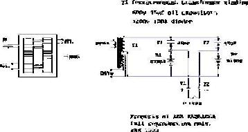
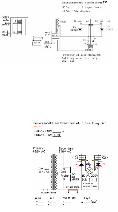
Example
Take a DEC 10 power supply Ferro-resonant transformer (DEC 16-1491 rev D); use 1200v 22.5 uF capacitor in the resonant coil. AC primary input of 444.6W (117V 3.8A) with 3151.5W (573V 5.5A) circulating power in resonant coil. If diode plug is used as in plan with x2 capacity, each capacitor will become a half resonant Tank circuit becoming in a sense a VECTOR accumulator one negative and one positive "half" in "resonant" mode. If discharged in sequential pulse mode the power is awesome compared to the input. The ratio in this transformer circulating power was over 7:1. All this time we were forced to assume this was a POWER FACTOR phenomena and that this power was not EXTRACTABLE in any way. Well not any more with proper tuning and pulsing circuits or simple "Spartan" resonant direct connections it can be used.
I hope you can find FR transformers or
get a standard one 120/240/480V primary 120/240/480V sec. Turn the secondary into a resonant tank; the
transformer will hum and if tuned right, will "drift" with input frequency "TUNE". In this case no shunt needed since no core secondary current "regulation" is going to be used.
Try getting a ferro-resonant transformer. Old voltage stabilizers are resonant transformers.
After this first step try diode plug use
x2 capacity. Note the circuit will not hum it will do a “punk” and input current will be a NO LOAD VALUE. But be very careful: x2 voltages and x2 currents will be present at plug +- terminals. Pulse-extract the power into resistor bank until the system goes resonant (hum), max "Q" if possible.
Radiant Energy and OverUnity Page 49
In a PM rotor the magnet translates as inductive VA-energy going into a capacitor (transform to VAR); the relation of L and C being RESONANT radiant ONE in half LC diode vectored tank the OPTO isolation circuit and BLANK energy firing non-reflective to source Stage is SECRET to EXTRACT ZPE energy.
So the transverter circuit recovery approach is a 2-gunned device where there is no excuse for whatever energy resides within it or the core used to be converted into DC +- vectors (poles). "Radiant" energy contributes to charge capacitor within Resonant circuit. Unit can be called in a sense a theoretical "Vovine feces" eliminator. If there is any (OU) this basic circuit will extract it from a coil at proper tuning parameters (RF tuning practices are the standard).
Try to replicate the FR RC effect and
use the diode plug system; this simple device make many obsolete by all terms. This is simpler and cheaper than the rotoverter 3PH systems.
Suppose we take a trafo 480V to 220V and feed it with 120VAC and resonate the secondary (pure LC, not diode plug). You need to raise Q, loss decreases to a point it self sustains like VTA configuration, as "reactor core" it self amplifies. In order to get the losses become negative to reach "self sustain”, the Stochastic resonance comes to play, transfer of H Heat to Electrical current. As Einstein-bose condensate is created: certain resonance conditions create hyper-conductivity, cooling at magneto-atomic resonance level where natural superconductivity exist, like GENESIS device (UFO engine) it freezes to absolute 0 as it works to max potential. This at extremes as condition can be exothermic were the Burn out occurs (usually were BROADBANDING and signal annihilation occurs) as the Ferro-resonance papers stated. (To make the Genesis device working, the core material Natural resonance must be determined as to determine C and L values. An ACUSTIC physical NOISE like the TRANSFORMER Ferro-resonance is heard
when such state is attained.)
LC needs to be Optimized (No loss) no welds, no shorts, no sinks (Like RV alternator taken to highest Level, but with difference it stays on and does not shut down). Resonance can make an ELEMENT a SUPERconductor (why you think they call it COLD electricity?)
(Note that Metglass magic is in kilohertz -megahertz range)
About resonant Electrolysis, the Sonofusion water frequency is 23 to 24.5 Khz and its harmonics up to WATER boiling 2.45GHZ (microwave oven magnetron) and down to 2.45 Hz where the gas action separation is increased ten fold
You can experiment with the transverter as vectored resonant electrolyser. In the first picture above, the R load can be the electrolytic cells. The coils cores and capacitor need to be tailored to a specific frequency, where they match the best gas production of the electrodes or plates in the gas chamber (requires lab work). The small diodes across C1 and C2 are power reversal blocking diodes.
Ferro-resonance
Ferro resonance is a complex electrical phenomenon, which is characterized by the sudden onset of very high sustained overvoltages concurrent with high levels of harmonic distortion. The system can take a sudden non-linear jump from its normal steady state response to a steady state condition of severe harmonic distortion. Ferro-resonance is distinguished from linear resonance (which is predictable) in that there exist several stable steady state responses to any given change of parameters, the response is very dependent on the initial condition, the resonance at a given frequency can occur over a wide range
Radiant Energy and OverUnity |
Page 50 |