

Phedotikov / 1 / FreeEnergy_27.01.08 / Механические / Energy ZPE reserch / Radiant Energy and Over-Unity v6
.1.pdfresonance).
To measure the current relation in a RV, use 3 current shunts (can be resistors) 0.1 ohm in WYE. One leg goes to the source battery, one to return (generator to be tested, DC output), and the third to the load (inverter). A common ground is used for all devices (G).
The inverter current must be the sum of return and battery current. As the return equals inverter current and battery current is 0 that is UNITY. When the battery voltage equals Return voltage = unity. As current reverses into battery and battery voltage becomes lower than Return voltage, that signals you got overunity. RV>BV=OU COP = RV/BV condition under full load.
That is DC Y bridge to measure overunity; an undeniable tool as it measures pure DC. Since 3PHASE DC outputs phases overlap, is very low ripple, hi rectification adding to DC purity, so no ripple artifacts can be attributed as to be cause of error in dc readings.
Hectors RV example with light bulbs
(see picture on Introduction page) First tune the RV to minimal loading (free wheeling - no mechanical load). In the alternator side seek 3 LCs max energy near resonance with less power input. Normal ratio of power in to Virtual LC power is 10:1 compared to input "minimal ©.Then READ the ampere load: that means the amperage of EACH LC, you seek a LOAD as filament lightbulb of SAME amperage (e.g.: 220 VAC 4.545A - 1000W - in series you put a 1000W lightbulb to that LC). Do not exceed R ampere rating as it can burn or explode the lightbulb. In case needed, put several bulbs in series and/or parallel to match the voltage and current.
The secret is the STANDARD AMPERES rating in the lightbulb MUST match the LC amperage at resonance. Call it Ampere Load, as in resonance the antinode condition is the only VALID reference measure, retune to compensate for R thermal ambient drift. In RV alternator you can SHORT a 1000W bulb to 0 resistance, and have circulating currents of 1700W with a minimal input. But as short is removed and bulb lights, 500W are immediately required by entropy transform within the voltage drop of bulb ... LC detunes.
Note: Radiant energy at low frequency cannot be used in mercury lamps as it teleports UV radiation within E fields, burning biological entity and causing cancer.
Put the bulb(s) parallel to a switch in “ON” position. Once the current node is attained, put the switch to “OFF (open it), and the current node will be over the bulb. In RF you have to turn things OFF to turn things ON. Tip: in LCR as R ampere load is put in LC, the added impedance Value R aport must be capacitor compensated to maintain target resonant state.
The coil is shorted by a (reed) switch, it goes to resonance impedance "max saturation less Lenz component, as short is cut OFF it dumps its collapsed field as a charge into capacitor. Where M Field is C and coil is L within a given core wire-turn relation that is
resonant relative to the magnetic field acting as a reversed rotary condenser (reversed current angle). Importance to short at the proper rotary angle and cut off at saturation peak, where this energy will dump into capacitor as a charge as the switch opens.
Turning things ON by turning them off, like simil of holding on spring until it stretches and releasing it as the mass pulling it becomes near null ... release and pull becomes push. The result is a power factor virtual logarithmic power increase relative to the Impedance increase where current I transfers to voltage V potential as field collapses & coil regausses to major greater impedance.
First experiment with one leg, then go 3 phase. The reasoning here is you are dealing with RESONANCE and your loading relation is in Phase differences and frequency shifting parameters.
Radiant Energy and OverUnity |
Page 31 |
The MASS relative resonance in NODAL segment is revealed here; a single filament matching the AMPERE load of a resonant LC will light at current node Under a MINIMAL voltage drop but giving Same POWER output than a conventional lighbulb (this is what EV GRAY called COLD electricity).
Note: be careful with a combination of smaller bulbs (parallel and/or series) as there is a mass radiation parameter that must be taken in consideration using series/parallel connection, some filaments being partially magnetic will not glow at all even having same ampere loading character (resistance ). Ohms law does not cover this nor other book data. Material damping of resonance does occur in some lightbulbs containing nicrome alloy (magnetic) in filament
Where I am getting the HV is shorting the coil with the switch, not turning it on-off...which is something new.
Entropic in logarithmic decay, its true radiated power becomes 1.618 in comparison to input "1" (ratio 1:1.618). A corresponding phase shift is reversed as entropy to primemover, but is usually .618:1 in reverse relation (in VTA and MEG this number was closer to 1:1.313 relation) 461.028W being 1HP not 746W. That is 1000W must be run with 618W at input at unity PF; same luminance as
lightbulb directly connected 220VAC. These experiments were done using 60CPS; as frequency increases so does efficiency. The idea is to series resonate LCR as to make virtual power becoming real manifest within physical entity of bulb to create a pure current node were voltage drop of bulb is less than 19.8 VAC being able to operate underwater (220VAC lightbulb as EV Gray demonstrated http://www.rexresearch.com/evgray/1gray.htm). Don’t try water stuff unless you got 19.8VAC tip to tip in filament, else BANG!
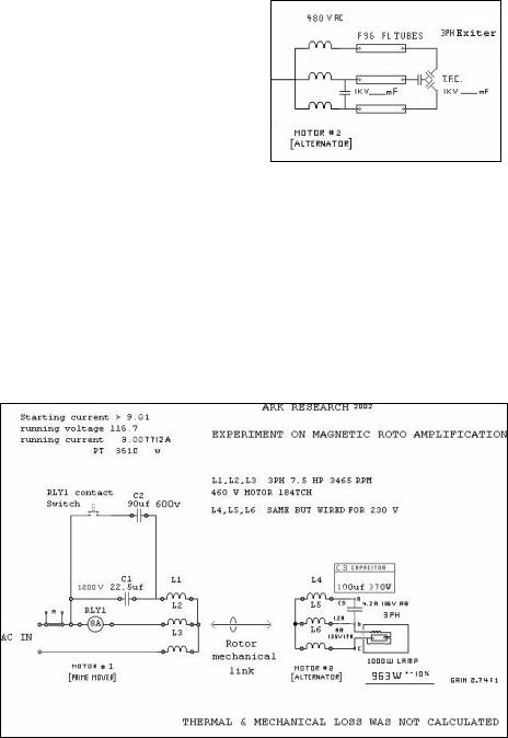
If your alternator provides high voltage (e.g. 790VAC – obtained with 1500rpm motor running at 3000rpm…), you can make tests with FL tubes. You set LC at 790VAC, connect a lot of FL tubes across a parallel switch and as resonance is attained you turn FLs on by turning switch off. (This is for intermittent experimental use, as ELF resonant wave carries the Mercuric UV signal.)
When Hector disclosed the resonant FLs tubes in SLC "1984" and demonstrated the 12W (75W simile) Luminic output, no one paid heed. But now you have 20W lamps giving 100W luminal output. Hectors goal was 8 footers resonating in HF at 1W, but they kept burning out. So lower frequency and less Q was used.
This is WAY over regular power engineering concepts but REQUIRED as basic for alternate energy R&D as this BOOK rules are the only ones properly justifying theory of TRANSFORMATI ON to support were OU truly comes from.
Tesla’s words are so easy to understand as he tells to tune the POWER source to the LOADS needs (he was using RADIANT
energy). That means his circuit was perfectly tuned in resonance at maximal energy wile supplying the loads power needs (simple).
Please see the pictures posted on RV and Zeus lamps. In resonance circulating power is 10 to 15 times the input of witch 1.618 is true logarithmic stochastic energy gain transformation.
Radiant Energy and OverUnity |
Page 32 |
Next steps and trials
∙Change the 3000 (3600) rpm alternator with a 5.5 kW 1500 (1800) rpm one, still connected in a 1:1 link, to have 100 (120) Hz at higher voltage and to attain higher Q. Add in addition diode plug system, and a proper transformer or variac for 165 volt input (EU). Note that the primemover rpm must be same or higher than alternator rpm.
∙Variac or Reactive compensated dimmer (Triac) gives you 220 to 0 volts adjustment giving you a range of greater experimentation with different voltages (full range adjustment).
∙Automate the switch on & off of the start caps with a current relay. You can buy this or make yourself. Raivo did this by wrapping 2 turns of (thick) wire around a toroid transformer. This wire forms the ‘primary’ is goes to the start caps. To the transformer’s secondary of 14VAC, add a full-wave bridge and a cap (1000uF), and connect this to the coil of a 12V 40A relay. If the current exceeds about 5A, the relay is turned on and starting capacitor is connected. After the required RPM has reached, the current decreases below the threshold and starting capacitor is disconnected.
∙Look for screws crossing rotor core, acting as short windings. Insulate those at one end eliminating short.
∙When energy is extracted from caps of the primemover, the input power goes 2 to 3 times higher that output. So let the prime mover act as PM; no power extraction from it. Attach alternator or generator to PM.
∙In the primemover, you can extract power by putting a resistive load (light) in series with the caps, matching light amperes to capacitor amperes, at the current node. Its very interesting what you can get with VA phase relation and valanced phase relation, try 3 lightbulb delta compensate rotation. Try to light the bulbs at same intensity (use safety eye lens in case a bulb explodes).
∙If you have a primemover with strong permanent magents, you can get OU from the primemover alone...but you might as well turning a generator if looking for maximum OU and perhaps a selfrunner. Going high impedance, rotary condenser becomes EMA (Electro Magnetic Amplification). As a M field atracts another M field of mayor intensity, the second apports energy to the first. Any EM rotor in any generator run in RVmode becomes a free energy device, first correcting PF and second pure EMA rotary effect (rotary condenser to rotrary Magnetic Amplifier). That is the secret of EVGray, Bedini, Newman,MEG, VTA … universal laws.
∙If the alternator is run with no load, any loss will reflect to the source as drag & power use increase.
∙Shunt winding (reversed opposing wire turns): rewire alternator to eliminate those. Test the core in an empty non wired run to test core magnetic drag, too much loss, use motor standard motor core with PM rotor and forget alternator if you cant find good ones with low loss cores
∙It’s easier to get an standard motor to work in PM pulse motor modes than to redesign in Newman, Bedini or axial mode ones.
∙An EM rotor RV can be used for the power factor correction and KVAR OU tests and experiments.
∙Take a modern motor with a modern PM rotor. Make sure it’s not oversaturated to magnetic drag like wind PM alternators are, and you have something interesting. See further.
∙Uses: cyclo-converters, power factor RC correction, asynchronous generation (Solar, aeolic, Hydro applications) Motive power (prime mover) tools, cars, airplanes, lawnmowers and infinite applications on other products all in low power energy savings modes.. (green compliant) products.
∙RE-WIRE a common 120vac motor to 460V and use 120 VAC. The 90 deg STARTING WINDING being tuned for best angle phase shading using OIL capacitors you get RV EFFECT. Also if you run 120V motor at 24VAC using right values of capacitors for starting and running you get RV effect.
∙RV mode can be made small using 1Khz motors and inverters but requires high expertise, the smaller the more expensive it becomes to create.
∙A 230/460VAC 3PH motor wired for 460V equipped with N S poles rotor as to work on ATTRACTION by means of PULSE management (120V pulsed) may be the easy way to make OU motor, as ATTRACTIVE force does not degauss rotor magnets. The CEMF can be collected by reverse diodes in IGTB or transistor switching array for a full 3 Phase "modified" sine wave operation (having the advantage of Bedini like PM magner operation and the Johnson wave effect).
http://freeenergynews.com/directory/howard_johnson_motor/blueprints/hard_replicate/
Radiant Energy and OverUnity |
Page 33 |
For a generator the best design is the MAGNETIC DISTRIBUTOR GENERATOR CONCEPT made with care to avoid shorting the flux path of AC magnetics.
∙Try paralleling some capacitance with R (lightbulb load ) to correct the LR POWER FACTOR loss (basic start). Or use NN or SS unipole induction and load the CEMF EMP non reflective to primemover coil charges in forward discharges at collapse.
Idea is to learn the basics to "bend" LENZ law, and lab tested RV is the best tool to do it. The LOAD as integral part must be tuned to source and source to load NEEDS.
∙Run your prime-mover from an inverter. For RV experiments, best use is >90% eff , least idle draw (<1A), with modified sine wave (no compound sine waves). For the required power, calculate the required Watts based on the motor size used. Keep in mind the starting peak power demand. For example, a 5HP motor might need 2000-2500W for 10 seconds to start, after which 1000W is OK for running load conditions. Consider also a safe margin, so a 1200-1500W inverter, with 2500-3000W peak is good. A microwave transformer can be used as inverter with a single transistor using 12VDC as input; to light FL 8 footers and as HI voltage source.
Variable pulse-width is essential to ring LC to OU states in hi Q modes. The pulse is tailored to get coil to saturation, as M field collapses it takes energy from thermal and magnetic ambient transferring it to the CEMP being OU in nature. See also “coil banger” and poor man thyratron circuits using disposable camera flash circuit and party strobe lights.
On HV-side pulselenght adjust the AC output to optimal impedance load relation , hit that 98% to 161.8 % efficiency areas .
RV is not friendly to frequency harmonics as it brakes at over-speed in high frequency, as VOLTAGE tends to go infinite. It tends to shoot to next octave, it de-phases third phase angle and brakes down as capacitor generates over-voltage at lower frequency than input line, becoming a solid conductor in an instant to hi frequency signal from input, equaling to a self induced short. Pulse-length control might mitigate over speed, LOADING at specific load also. Variable speed inverter permits to find best performance figures. The RV may be reflecting power back reactively across inverter TR diodes maintaining switch on and shorting it to overload. Try a 5uF capacitor parallel to input line to take input load at start as more "resistive" surge disconnect as rotation is attained. Some inverters simply can’t take reactive loads too well especially cheap imports, so use higher power version.
As RV starts there is a hi Q resonant vectoring creating the initial narrow-banded hi power starting rotary currents within the 3PH vectors. As the motor accelerates, the impedance relation to a receding impedance equivalent to a 0 Ohm short in rotor is transformed to impedance traveling toward infinite resistance (600+ ohms) as rotor attains synchronous speed and locks to rotary field in a LONGER very broad-banded region of resonant crest in apparent on resonant condition with a resulting very low power consumption.
In any case the impedance of the circuit will be changing if you run from an inverter. Now you must optimize as to permit MATCHING in START capacitance to INVERTER and run capacitance. If the motor can’t start on the lower power curve adjusted to inverter, switch to the inverter when the prime-mover is already running from household power, and then adjust running capacitor for best rotation performance.
Some inverters permit pulse-length time adjust. Find if yours can be adjusted using scope. On power, use DC shunt to battery DC readings for total power use. Your AC is a localized loop in a second stage, PF can give you higher readings not related to real input if by sample you get 10 to 30 amps in inverter that is a more real reliable reading as is a no meter lie DC parameter. The target <15 amps 12.7VDC or lower.
If the inverter transistors are H reverse diode protected from the DC high V, in semi-resonant synchronous condition power factor feeds back to DC capacitors in the inverter, as RV goes leading. This condition is OU within what I describe as producing a HYPERWAVE.
In past postings I mentioned an alternative to feed RV alternator hi output directly to the inverter HI Voltage capacitors itself, and downstep the power to a battery using parallel AC trafo from AC end to low 12.7 VDC conversion to attain battery feedback. This testing must be done with battery charged to optimal 12.7 to 13.8 VDC, as you may be getting low-V inverter shutdown and may not be a hyperwave.
∙VFD (variable frequency drives): customize a 3PH modified sine (square) wave inverter, by downconversion from 220VAC to 120VAC, and pulselenght adjustable with 3 phase IGBT bridge with 6 reverse diodes in 3PH diode recovery bridge configuration. Specify as 20 to 470Hz and 1 to 90% pulselenght adjust, and drive a generator to the "sweet spot" and get instant OU....
Radiant Energy and OverUnity |
Page 34 |
∙PF correction: If you take a 10KW generator, 120/230/460 VAC 60CPS 1600rpm (4 pole) ring exited rotor (brush). Replace the regulator with manual or current regulated adjust EM excitation power. When the system is wired to 460 VAC, a pony RV starts is to synchronous speed with the grid. Once is synchronous, connect to line where excitation voltage and current magnetizes rotor creating RV power factor correction synchronous dynamotor. This connected to your house reduces power factor loss to 0 with adaptive sensing and adjusting. That is 40% energy savings average. Use PM rotor this feeds EMA OU power to home, use series variac to regulate KVARS or Magnetic current regulated amplifier to control PM KVAR output. In places far away from grid power source this can save 60% on power bills correcting PF line loss.
Controlling
A governor can be used to regulate speed with a hi speed disconnect low speed reconnect cycle. The excess charge can be passed to any 127V UPS or inverter system (off the shelve) and monitor its battery charging capability. Then next step is to increase to RV type KVAR 1 to 10kilowatt range, without having to build a Newman motor alike monster. A 3HP PM motor operating at 15,000 RPM can transform 30 HP of energy (22.38KW); if 0.382 of that is OU definitely we have a practical device 8.5 usable KW. The solution for extracting this energy without destroying the effect producing it, is where the resonant diode plug and optical switching become useful, as PARTIAL extraction and NON-reflective vectoring can be attained (schematics & pictures in PDF files).
Same can be done in Solid state Modulating caduceus like class C linear amplifier after you find the proper EM relation, the battery just becomes reversed in time, causing ATOMIC mass increment in lead atoms PB206 reintegrates to radium and so on. Nice stuff to manufacture cheap plutonium if you use pure lead plates and heavy water in your battery system. Normal batteries contain bismuth (neutron moderator) that sulphates in Fusion modes (burns) destroying the battery.
Looping the RV
For direct looping the RV system, you need integral wave Cyclo-conversion. If not then you need a battery for power conversion, because asynchronous motors without permanent magnet have a slip, as such creating a lower frequency. Also the prime-mover frequency must be higher than the desired alternator one, due to the slip (speed must be compensated in AC). In DC it’s just having more volts and current, than at the input to inverter.
There is vectoring that comes to play, to convert those radiant states "OU" to a real vector potential Q, resonance and phase angles are the key; with proper tuning stable looping is achieved within a charge-discharge cycle operation (OU – under-OU – OU – under-OU cycles like Kone did) in a wide shallow cycle.
It’s good to have a broadband quantity of capacitor values to play with the tuning set-ups ... can be tripleflux delta - wye combos with transformers, diode bridges and diode plugs.
In Hector’s RV looped schematic, the Radiant Energy can be coupled through the trifos like standard electricity by applying the RF and power transform rules.
See http://www.ibiblio.org/obp/electricCircuits/AC/AC_8.html . Radiant energy must be Rephased in order to be transformed properly in standard transformers or use RF homopolar transformers.
Tip: you got Alternator VOLTAGE relative to IMPEDANCE and capacity; Hi voltage lower capacitance ...
LOW VOLTAGE HI CAPACITANCE (sample 200V-100uF; 20V-1000uF; 10V-2000uF). Interesting to note that the CORE density is relative to L1 HV to L2 LV, where CORE defines L1,L2 Q relation whe²re null zone is within CORE itself (reread info re ferroresonance recording commentary).
Being alternator PM, then C can be in a value to aquire charge in logarithmic resonant half waves (DIODE PLUG) wherever on reverse induction we need to maintain pressure wall reflective to source to maintain the core self exitation. Values need to be rotary standing wave within a given voltage value determining the broadbanding of signal (in this case Hypersignal).
The swing of particles within matter from + electron values to negative POSITRON ones in hyperdimensional fabric where electron becomes elektron (with K) charging energy from timereversal hypesignal, is what makes looping self subtaining, but at same time DEGAUSSES and transforms LOCAL time-space into a singularity.
On RF the trick is feeding a HI Q 60CPS LC with the battery being a plug capacitor load on it. Compensate for VARACTOR detuning effect. It’s no Mystery but a matching and in vitro application issue. (http://www.nuenergy.org/alt/energy_amplification.htm) The need to keep to the BASIC essential where the OU transform manifest is the key.
Radiant Energy and OverUnity |
Page 35 |
Remember R represents a series L to L and series C to C, and reflects as such a purely resistive load were RA and RV are theoretically in phase at a 0 angle or POINT in SPACE, like the centre of a balance in an equilibrium. So the REAL value is a virtual Ampere load as seen by the pure LC where Voltage is not reflecting the reality of that point but shifted to other point within the circuit ... node, anti-node. In ZPE and magnetic amplification this is the difficulty the experts stumble, the reality every part parameter reflects in the other.
A battery by sample, its L its R and its C, has an intrinsic resonant value as a unit or its parts, it’s a self tuning on state device with those R, C, L values being VARIABLES within a working unit. The reason Kone-motor was working in OU - non OU cycles and the reason Engineers failed to analyze properly. ED also met the wave within the Wave oscillations in a partial loop.
The battery as seen by L from a rising AC half sinewave is C "capacitance", when CL frequency equals the WAVE frequency, the POWER multiplies by 1.618 in LOGARITHMIC EMA; this multiplied also by Q EMA factor ... gives OU gain over Isotropic virtual dipole. (a need to know in deep Bedini and Kone design and the term Hector used that BEDINI just POWER FACTOR corrected his battery…).
Increase C in LRC to compensate R broadbanding loss . If mathematically we have sine & cosine, it is obvious in energy we got same manifest that represent energy transform. The famous “negentrophy” Bearden mentioned so much, but failed to demonstrate others.
If the diode plug recovery circuit/impedance match test with the 10:1 trifos is successful, then try to find out how one can connect three trifos & plugs to a single battery.
Similar or identical motors, identical will be interesting as the radiant readings on the alternator side and temperature versus impedance issues can be compared, also as is, motor alternator gives flexibility to use to "primemove" any other machine "2 RVs ".
RV with Permanent Magnet rotor Alternator
With PM-RV, first you win the slip and rotor energy losses, and second you have the PM magnet amplification effect (which must be well designed).
RV with PM (Permanent Magnet) rotor can be used. PM force must be calculated as not to over-saturate the core. Konzen motor type experiments and Raivo & Rain Electric Turbine modeling. 15,000RPM and 11k of centrifugal energy spinning rotor. These motors in PM version can be operated in Pulse mode, where the magnetic phenomena Amplification does occur (Kone had attained in vitro in his advanced pulse motor conversion). Secret is Frequency and pulse-length & voltage intensity adjustment to attain overunity (Magnetic rotary amplification).
Reasons to build PM RV from 3PH motor:
∙optimal size (10HP), advanced "toy"
∙relatively easy, standard (it helps us to advance more quickly using standard methods)
∙BUSINESS OPPORTUNITY: I recommend production - as would probably find many (10+) people in the EVGRAY group willing to buy (synchro-motors are far too expensive to buy).
∙wide area of use: you can use these as 3PH motor, PM RV, PM alternator, wind gen, PF correction
∙it is OU
A continuous RESONANT wave surfing PM rotor makes the RV superior to ANY other motor ever made. Such state can be obtained in HI impedance RV effect using modified sine wave inverters. That’s the advantage of 3PH 90 deg force vector and oval shaped rotary
Phasor fields.
A PM RV pulse motor is the best mix of the 2, and there is a lot more as this is only the tip of the iceberg (ref. to Hector’s 111 phases Electric Axial coreless turbine). If you convert RV to PM you can pulse it with 6 reed switches or Opto-Transistors and 6 recovery diodes in 3PH bridge.
Metal for half moons & centre body parts recommended is speaker end plates, Mu metal alloy low remanance hi conductivity HF harmonic tolerant. Or for the Half Moon, use ceramics 5 & 8.
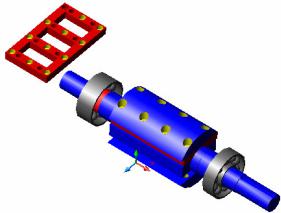
The half-moons on the picture to the right (© Raivo)
Radiant Energy and OverUnity |
Page 36 |
are made of magnet conductive steel, as is the central part (2-pole diagram in picture). The rotor must be highly conductive. The red “sleeve” or “jacket” is made of dur-aluminium (or stainless steel, but expensive to do) in order not to short out magnets and to make the structure strong (the drawing is for 2 x 1 x .5 ©strong NEO magnets). Depending on the motor power rating you may need a version with maybe 5 magnets in a row (total 2x5 = 10). The magnets are oriented such that one half moon is North and the other South, so 2 poles N-S. The magnets must be separated from each other, then the field distribution M force lines choose the iron core path instead of themselves, so to help localize the field to metal core.
Flow: stator <-air-> (half moon ( N-magnet-S (CENTRE (O) STEEL) N-magnet-S) half moon) <-air> )stator. The most important part is that it must be well designed so the <-air->gap must be minimum. The power will depend reversely on this air cap.
If the magnets are too powerful, it over-saturates the core (laminations) under room temperature (Meismer effect - partial superconductivity). This creates a high drag at magneto-atomic level; separate from core, loss decreases as field drag decreases. Also distance influences impedance of coil so it affects timing circuit effectivity, shortening or narrowing pulse CEMF. Find its magnetic saturation point at given frequency voltage and current potential If you cant move it with a finger at no loading ,the engineering is no good and generator is no good for ZPE and or RS (Rotoverter System work). The importance of the meaning LOW lenz component is a LOW reflection of mechanical POWER to the primemover, so it’s ovious by now that if a mechanical system is loaded by the generator it drives way over the energy it produces its not OU.
A car alternator is 37% eff average, but electronics needed to regulate the voltage. With a PM rotor nonsaturating, the eff is 75%. Using proper core 98% to 161.8% eff (resonant) hi Q. Right now 99.999% of all generators commercialy available are unfit for Alternate energy and ZPE R&D use.
The iron or steel in the stator cores in existing 3ph motors is good and fine if you have constructed a homemade or modified PM rotor, ONLY if the magnets are fairly weak ones (like maybe grade 10 neo for instance). However if you use the strongest neodymium magnets in those rotors, the LATCH against the iron/steel (even if laminate) will ruin any sort of advantage of using strong magnets. So this means AIR-cores, or black sand cores or metglass stator cores.
If you use grade 45 neodymium magnets, there is not going to be any resonation in those cores, just a lot of latch, "pulling" everything "one way". Perhaps with lots of power input, you could balance-out the force of the neos whirling inside the iron stator cores, BUT then you get HEAT PROBLEMS with iron or steel cores. If building or modifying your own motor, you should use the strongest magnets possible. Then against these super strong magnets, the coil©s cores should be/have to be: air, black sand, or metglas (no heat build-up when lots of power from low hysteresis).
This will be near impossible to do with the stators in existing 3ph motors - some will be better, (laminates) but they all have too much latch against strong neos. Everything that happens mechanically and dynamically with a 3ph motor can be done "axially" as well as the existing standard "radial" design in 3ph motors; this by sidesaddle stator banks, and Muller-like imbedded-magnet rotor in between. It’s simple to make motors like this, probably much easier than just machining a PM rotor to fit inside existing 3ph rotor.
In order to determine the magnetic strength needed (how many magnets and how strong), have Gauss readings of the CORE metal subjected to M field & let that field collapse under controlled conditions to get highest CEMF level at minimal gauss. This can be determined by pulse discharge and other methods, conductance, remanance, reluctance are important to ROTOR -stator relation parameters. Excessive powerful magnets will create DRAG & heat from a given point further; intensity creates undesirable eddy current effects. If the magnet is too strong, the laminate becomes a shorted conductor turn to it creating drag, so core magnetization, core material, speed, ampere turn, intended load, impedance and a lot of detailing must be done to acquire ART perfection necessary for improving current technology to standards required for OU transformation.
First, obtain good motor 3-7HP that takes normally let’s say 60W max (good bearings, no fan) driven in RV mode. Take it into pieces and measure, print out this schematic, calculate new dimensions and let specialist to make PM motor for you. Also old compressor motor cores can be used to make PM generators if good (compressors usually fail due to valve problems). Cut sealed compressors along the weld line, 3/8 deep. Advantage of compressor stators is that they are not painted or epoxied. They can be rewired more easily.
The target in a generator is no load near 0 mechanical load. Coreless PM gen 0 load must be no higher than
.003%. The target in a motor "Primemover-driver" is no load 0 power demand.
In PM (permanent magnet) RS (rotoconversion system) motor synchronized to line is SYNCHRONOUS CONDENSER MACHINE and provides KVARS to system in OU EMA modes at HI impedance.
Radiant Energy and OverUnity |
Page 37 |
That is MAGNETIC ROTOR field intensity determines KVARS injected in supply system ... an EM (Electromagnet) driven system makes it possible to control PF and Electromagnetic Amplification EMA level, also adjusting Rotation angles (phasors) of electric signal (Power).
Suming it up perfect generator minimal drag at no load; maximal power output with low loading to source. Perfect motor minimal Power use at no load max eff at loading in HP output (lowest power usage per HP).
Using Permanent Magnet rotor all HP ranges can be used by frequency and speed being determinant of performance to EACH motor, PM must never exceed the saturation of cores; this MUST cool down but never HEAT up under semy resonant power. Generating or working as a motor (Prime Mover) same factors apply.
Every motor and generator has an OPTIMAL speed & frequency and Loading factors, where it is more efficient and performs the best.(Lab proven & tested ). Within a certain RANGE, most of them can exibit overunity phenomena due to natural magnetic amplification EMA effects.
If someone has real interest, the path to follow is to buy existing MOTOR manufacturer and convert part of a production line to built PM RVs, and contract Hector for re-educating the engineers in a lab.
IMPORTANT: PM rotor motors MUST be synchronized to AC field rotation and turned on.
PM Multi-phase dynamotors
On generator design using PM DC motors: DC motors do not make good generators "as is". If you disassemble one you can see the brushes and the area of commutators they touch. In the case of a Baldor DC motor if you have 40 commutators in 40 windings delta connected and the brushes touch only 2 commutator segments, you are using only 1/10 of your rotor winding, plus the others become shunts drawing power from the first, an independent star configuration prevents self shunting.
This is the same as the generator diode bridging in 40 Phases Bridge, which uses full potential of windings in overlapping phases in a continuous DC stream in magnetic PM top N-S field crest within the structure.
Good test is to create PM end bell from PM DC motor and rotate it with RV in a full phased Wye rewired DC motor rotor (now stator) and quantify energy generated in pure DC. That is raw 4 times over the full load capacity of motor at 10 times more efficient, depending on the quality of motor and rotor laminates. Some really suck! RV permits you to see were they are poor and where quality and design influences performance.
In repulsion mode charge comes from overshooting the receding field and is more practical to have repulsion & attraction at 90 deg. Here is where 2 pole rotor & 3 coil in 3PH configuration becomes handy. Tuning the device impedance with capacitors makes the battery become a negative resistor within the rotary LC tank where the magnetic field and thermo magnetic mechanics provide the OU energy transform from ambient. All you need is to install a limiting circuit as 10 batteries exceed 127VDC charge circuit disconnects until battery drops 100 volts then circuit is reconnected to recharge them again that way you have a self recycled self runner.
Then you can build a PM RV and do the same with a standard frame motor. The switching can be connected where the fan used to be, be it commutators, magnetic reed or optical switch.
So as an advanced search to lower the cost in making super E PM motor-generators, you can make a multi-phase alternator from a PM DC brush motor. Prepare its stator to be used as a rotor, and its rotor to be used as stator wired for 3 phases or more (Hector took a Baldor
CDP3455 motor). If we see in a DC motor, only a segment of its rotor contacts the brushes 1/5 to 1/20, so if we fix the rotor and as a delta 40 phases (example) winding place diodes on each segment, our 1 HP DC motor becomes a 10KW AC to DC 40 phases generator.
The diodes must be placed as follows: 2 diodes (one positive one negative) to each segment, all negatives to common negative, all positives to common positive, all wires same length. 40 phases, rectified 9° each apart from the other = super low ripple DC double voltage 5 amp per segment; that is 360V at 200A max (72KW) surge max (hi speed) ...7.2KW constant rating low speed. Interesting to concentrate such power in under 20Kg.
Each commutator segment is a phase - they
Radiant Energy and OverUnity |
Page 38 |
overlap at 360/P where P is number of commutator segments wired in DELTA. (Read Tesla 3rd brush regulation: "he was telling something BIG there", but no one noticed). Divide P by 360 and you get the phase angles. Calculate the peak of each phase in time to get the ripple factor (e.g. 44 segments = 8.18° phase angle = ripple of 1/4%). So the ripple is near 0, except for the edge modulation caused in the rpm x number of phases x 2 (poles) harmonics. These will be also rectified and filtered into DC component but complement strongly at slow speeds.
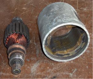
See picture to the right of a disassembled PM DC motor with 44 segments. This motor goes up to 15000 rpm.
You can use H steel beam to hold stator as end bell in long shaft, and prepare the rotor as stator with the commutator segments tapped to use as pulsemotor, generator and dynoconverter; or just drive it with RV to address the PM drag issues and design. Preliminary experiments can be done with PM fan motors, air conditioner FANS, wiper motors, blower motors or any PM stator brush DC motor.
The PM ones Outer Stator is placed in cup at end of shaft ....the rotor is fixed to a plate as to fit like original inside but is fixed to it non rotating , the commutator is then diode bridged as a multy phase alternator , if laminate is good quality.
Since rotor magnets are inside, centrifugal force maintains them in place inside cylinder. It can also be micro valanced for hi speed 24K RPM; that increases power to 50KW, using hot fast switching hi voltage diodes. But this thing can generate power by moving it with the hand.
Any PM car motor can be converted to multi-phase alternator, like the fan, wiper, air conditioner fan. Just disassemble a toy motor (3 phases) or car wiper motor (12 to 24 phases depending on make).
In starter motors, the PM stator made into rotors are OK for hi current hi speed low voltage DC generation. 10 diode rectifiers from standard alternators work the 33 phases (Delta) 10.90909°. You can fire 3 phases segments in pulsemode to get not 15 but 100HP at 30,000 rpm (depends in laminate quality). You can pulse 1 segment each 4 steps and “pulsemotor” it to hi speed super HP RV dynamotor Turbine. The diodes will recover every CEMF you can create there; also you can run in 3PH and generate in 12, 24, 40 phases or whatever phases your DC commutator segments may have.
Further reflection on PM-RV and PM-DC motors
The DC-PM-RV rotor is a superior efficient running motor design. The PM RV rotor eliminates the motor’s slip loss in the RV generator side, therefore increases the efficiency to 100%. A slip is a poor design that squirrel cage motors (currently used as RV Áhosts©) are designed with. Doug Konzen has already modified a 5hp 3PH motor and eliminated the loss of the slip via this modification. Important core drag issues are still on the R and D table with this method, but it is workable. What is needed is a PM rotor designed as to be magnetized to near saturation point but not exceeding the CORE saturation as to have minimal on NO saturation drag effect. It is also a R&D method to quantify the issues in the reverse dynamometer capability of RV.
Using a PM RV and 3PH pulsing & recovery is the way to go, and the reason why synchronous motors are getting eliminated is to get rid of OU manufacturing devices. (http://www.tpub.com/content/neets/14177/css/14177_101.htm).
DC/AC Rotor conversion: http://www.tecowestinghouse.com/Products/Custom_Engineered/synchronous.html. Read and wake up as a great truth is being repeated here that if you attract a greater force with smaller one, the greater will amplify the smaller one. The word leading implies power production ,OU due to magnetic amplification the so called power factor correction is the answer to OU transform "KVARS".
You supply a greater magnetic field to a synchronous motor rotor and it will produce more power than it consumes leading PF (Secret OU terminology).
The PM-RV is related to the concepts of resonance hyper Q states, logarithmic and the magnetic amplification factor in LCs. Easy transferable to RV in a low voltage hi impedance rotary pulsed machine. With a PM-RV design, pulse driven with logarithmic power and CEMF recovery in a full phases diode bridge; 3x3 configured or (n X n) - n being the number of phases used as in a multiphase PM generator-motor concept.
All that is required is a standard 230/460 3 phase motor with a PM rotor designed as to be magnetized to near saturation point but not exceeding the core saturation as to have minimal or NO saturation drag effect. Secret is tuning into the resonant states and optimizing use of the power attained without killing the OU LC effect.
As in a stator the PM rotor within a given impedance makes this resistor negative as the voltage drop in the line is minor than the voltage drop in virtual LC resistor, as the generator works in synchronous HI impedance rotary condenser mode. This results in Electro Magnetic Amplification were H = I2Rt EMA, where apparent
Radiant Energy and OverUnity |
Page 39 |
power contributes to source power on other mode of resonance taken to a PF corrected Nul, Zero Point energy state VAR production in HI virtual OU impedance value. (Ref. formulas http://www.nepsi.com/formulas.htm).
The M field is your power source when you create a self amplifying amplitron RV-PM alternator. The fact is that any high efficiency generator wired to 460VAC and run synchronous in 120VAC can be used to make and demonstrate this principle. Once understood a PM generator is wired as to create these effects.
In this configuration the LC is seen as a resistor and as such you read amperage and multiply by the voltage source and get its voltage drop value (basic Ohms law). As the voltage drop in the line is less than voltage drop in the virtual LC resistor, means that the virtual resistor possesses energy transferred from attracted M field to attracting M field.
In impedance matching its current must be equal. Even if the resistance is unequal, Voltage and Resistance are the determining variables to match virtual resistors and reverse energy to source where then current reverses being of a larger magnitude than the source.
As the LC voltage is induced, it attracts the rotor magnet so M1 attracting magnetic field attracts M2 summing and exceeding M1 turning the virtual unity resistor to a negative over unity resistor, as its energy level is more than the one supplying it (source). That means the current at a given point reverses to the source supporting energy to it, usually in VARS as PF and cogeneration laws apply.
Rotary condenser machine (http://www.pscpower.com/pages/series%20sc.htm): if we see it from a perspective they "re-gauss" the utility lines making you save energy. In high impedance they become EMA (Electro Magnetic Amplifier). It©s simple: a coil attracting a magnet of higher magnetic intensity will get induced power from the stronger M field. In low impedance this effect is not noticed much, but at higher ones it exhibits OU due to EMA effect. Calculate this with hi impedance relative to M field in PM rotor synchronous machines.
This theory is also clear in PF correction using PM rotors to attain over unity in hi impedance modes as an EMA. Any motor generator can be modified to attain these modes as is off the shelf, properly designed PM rotors and stator cores can do marvels to already existing devices (modifications) to increase efficiency and performance.
Drag issues must be settled where you must find core fundamental frequency (natural resonance) then test by building a coil and capacitor tank to use this frequency in resonance and spin your magnet at this frequency and measure the circulating Watts.
The voltage used is determined by the LC needs to attain saturation & mechanical rotation within the EMA operation mode. ED GRAY operated on pulse. The RV demonstrates that such a system can be operated in continuous low voltage hi impedance AC feed and amplification mode. It takes a bit to understand Rotary condenser theory and W-VAR relation, all it takes is to study PF correction and RV to build a self sustaining OU machine.
Gunning and overunity
Gunning is the term used as you reverse polarity in a running DC motor as to reverse rotation instantly without stopping the motor completely. AC gunning creates extreme lagging power factor figures resulting in creation of extreme KVAR energy pulse EMP .. in case of switching BOUNCE small gap resulted in instant evaporation of hundred ampere rated switches or relays (due to ARC discharge of extreme EMP potential).
In case of VECTORING, gunning can be transferred from a negative KVAR region to a multiplied and amplified charge in a capacitor within plugged LC configuration where this CHARGE can be non reflectively discharged and isolated from main magnetically driven LC component.
Applying this to asynchronous coil induction and using Capacitor collected EMP vector potential as paralleled DC stream will add the EMP as class C magnetic amplification signature resulting in overunity ... as asynchronity will tend to charge some coils in REPULSIVE mode against MAGNET path certain degrees of Lenz effect neutralization will take effect within the alternator.
You will have coils being repulsed and others in attraction lowering rotor magnetic drag as one wave overimposes over the other circulating clockwise and counter-clockwise within a virtual torus, were these rotating components meet the amplification effect occurs being of REPULSINE electric nature (ZPE), the EMA effect is taken from magnetic field modulation and alternation at same time adding as vectors as contrary to entropic standard system where they result in loss subtracting potential from each other ...
This explains some Kones postings about Muller generator making Muller a bit more RV alternator alike but with the big difference of its asynchronous and PM character advantage.
Radiant Energy and OverUnity |
Page 40 |