

Phedotikov / 1 / FreeEnergy_27.01.08 / Механические / Energy ZPE reserch / Radiant Energy and Over-Unity v6
.1.pdfRadiant Energy and Over-Unity
Version 6 – October 2006
Dan Combine
Document name: RE-OU-v6.1
Radiant Energy and OverUnity |
Page 1 |
INDEX |
|
|
|
1 |
Introduction.................................................................................................................................................... |
3 |
|
2 Theory of RE phenomenon and OverUnity................................................................................................. |
4 |
||
|
2.1 |
Learning.................................................................................................................................................... |
4 |
|
2.2 |
Researchers ............................................................................................................................................... |
4 |
|
2.3 |
Theory of operation .................................................................................................................................. |
5 |
|
2.4 |
Magnetic attraction .................................................................................................................................. |
10 |
|
2.5 |
About core coils and PM magnets ........................................................................................................... |
10 |
|
2.6 |
Levels of transformation.......................................................................................................................... |
12 |
|
2.7 |
Electron Spin ........................................................................................................................................... |
12 |
|
2.8 |
Load & battery circuits ............................................................................................................................ |
13 |
|
2.9 |
Capturing or extracting ............................................................................................................................ |
14 |
|
2.10 The Cornu spiral (or Euler’s spiral) ......................................................................................................... |
18 |
|
|
2.11 |
Summary of RE manifest......................................................................................................................... |
18 |
3 |
Practical Applications................................................................................................................................... |
20 |
|
|
3.1 |
Rotoverter ................................................................................................................................................ |
20 |
|
|
Overview of Operation ..................................................................................................................... |
20 |
|
|
What you need .................................................................................................................................. |
22 |
|
|
In practice ......................................................................................................................................... |
22 |
|
|
The roll of impedance....................................................................................................................... |
27 |
|
|
Efficiency and Torque ...................................................................................................................... |
28 |
|
|
Hectors RV tests ............................................................................................................................... |
29 |
|
|
Hectors RV example with light bulbs............................................................................................... |
31 |
|
|
Next steps and trials.......................................................................................................................... |
33 |
|
|
Controlling........................................................................................................................................ |
35 |
|
|
Looping the RV ................................................................................................................................ |
35 |
|
|
RV with Permanent Magnet rotor Alternator ................................................................................... |
36 |
|
|
PM Multi-phase dynamotors ............................................................................................................ |
38 |
|
|
Further reflection on PM-RV and PM-DC motors ........................................................................... |
39 |
|
|
Gunning and overunity ..................................................................................................................... |
40 |
|
|
Micro-energetic cyclo-conversion .................................................................................................... |
41 |
|
|
Coil-Core-RF-DC repeat .................................................................................................................. |
42 |
|
|
Further considerations ...................................................................................................................... |
43 |
|
|
Q& A of RV replication ................................................................................................................... |
45 |
|
3.2 |
Transverter............................................................................................................................................... |
47 |
|
|
Overview of Operation ..................................................................................................................... |
47 |
|
|
Example............................................................................................................................................ |
49 |
|
|
Ferro-resonance ................................................................................................................................ |
50 |
|
|
Ferroresonant transformer ................................................................................................................ |
51 |
|
|
TV REPLICATION.......................................................................................................................... |
52 |
|
3.3 |
Homopolar transformer............................................................................................................................ |
53 |
|
3.4 |
Reactor Core ............................................................................................................................................ |
54 |
|
3.5 |
Kone pulse motor..................................................................................................................................... |
56 |
|
3.6 |
One-wire bulb - Brian Prater (Cavetronics Labs R&D)........................................................................... |
59 |
|
3.7 |
JM Pulse Charger..................................................................................................................................... |
62 |
|
3.8 |
Positive-bias inverter ............................................................................................................................... |
63 |
|
3.9 |
Relation to Testatica, VTA, crystals, … .................................................................................................. |
64 |
4 |
Summary ....................................................................................................................................................... |
66 |
|
Radiant Energy and OverUnity |
Page 2 |
||
1 Introduction
This document describes the Radiant Energy as discovered by N. Tesla, and further used by researchers like E. Gray. It covers the principles of generating RE, as well as several practical applications. In proper tuning conditions, this energy can be tapped and overunity can be achieved.
The RE (Radiant Energy) phenomenon itself occurs when a RLC circuit has the appropriate impedance, is in resonance and when a standing wave is created. Because of the L (inductor) and C (capacitor), there is a 90° phase shift between V (voltage) and I (current in Ampere) vector.
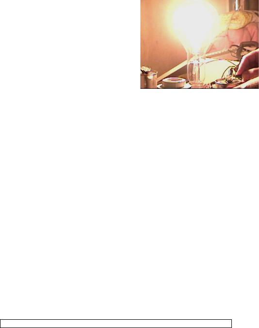
Example: the picture to the right shows a 230V-1,000W bulb lighted under pure resonance as ampere-load where the filament runs within standing wave current node as a single potential vector. The voltage drop being minimal, in this case it was 19.8 VAC.
Free energy and overunity are a TRANSFORMATION. We can learn its tricks and have all the free energy we want. But first the art must be perfected. You can’t get free energy from something that wastes 90% of it, like standard nonloaded motors, prony-braking it to death (detuning) or low impedance magnetically mismatched power generators being 57% efficient. So the importance here is to create OU states (Radiant Energy), "already done" in the RV
alternator. Then use this energy in applications and understanding its intricate effects and phenomena.
The RV mode of operation permits to quantify other devices such as the TURBINE development (Implosion Turbines); once the turbine starts its endothermic energy transform.
This document is an interesting compilation of the principles, rules and mechanics involved. It gives also a practical guideline for the serious researcher in this domain, as the results explained in this document have already been achieved and demonstrated by several ‘replicators’.
For more information on AC, RLC circuits, resonance, Power Factor… please refer to the following websites: http://www.ibiblio.org/obp/electricCircuits/AC/index.html http://hyperphysics.phy-astr.gsu.edu/hbase/electric/serres.html http://hyperphysics.phy-astr.gsu.edu/hbase/waves/standw.html
All information is public domain, copyright © by ARK Research, unless otherwise stated. The following are references to the first RV system disclosures by ARK Research:
∙RV looping - Predates to 1983-84 period; one of the 16 methods is at Don Adsitt’s site; http://www.theverylastpageoftheinternet.com/ElectromagneticDev/arkresearch/rotoverter.htm
∙RV -Ecklin-brown prime mover: Concept 1980; built 1983-84 SLC Utah US (looped);
∙1987 Macro electric open 100w to 1kw asynchronous mode generation;
∙1997 full disclosures on the internet;1999 reposting as sites were removed, blocked & cut down;
∙many internet postings done on magneto-transistor concepts, Recovery Diode concepts, transformation postulate for OU; all predating MEG, Newman and Bedini ones;
Applying the RV effect does not constitute the right to patent as the Roto-Conversion RV effect is a free domain application to such machine mode of operation in OU states. Any patent based on Roto-Conversion theory can be challenged. For further and updated information, please refer to the EVGRAY Yahoo group and many of the specific postings by Hector D Peres Torres of ARK Research.
The date of this document is only indicating when this document has been compiled, not when the information has been publicly disclosed.
Radiant Energy and OverUnity |
Page 3 |
2 Theory of RE phenomenon and OverUnity
2.1Learning
Use the technologies described in this document, and in particular the RotoVerter (RV), as R&D tool first. As you learn what ZPE is and the circuit meanings, you can convert any inverter to a ZPE device using pulse-length & frequency tuning under a positive-bias modification.
I recommend you to study Power Factor theory, Magnetic amplification, Phasors, rotary angle power-voltage relations, rotary capacitor power factor engines… The statements made in this document will become clear as where the OU energy is. As you reach a point were there is a shift toward higher understanding on next level, Hector will include more variable solutions to the problems you encounter as they are realized in vitro as real tangible non deniable facts. What Hector revealed is tailored to be only understood by those doing the experiments and having the spiritual right brain development.
The concepts explained here, like RotoVerter effect, Rotary Roto-Conversion and TransVerter (TV) plugs are part of a mayor development. Firstly we give you the instrument and test tool (RV prime-mover) to be used to quantify whatever loading you desire to test in its range, especially to design OU generators. Then we give you the key of RESONANCE for radiant energy generation in RV alternator concept, using reverse induction, including to attain those LOW LENZ PM-Coil energy pump generators live. Use RV alternator to generate R.E. and learn its secrets to apply later in vitro. Transfer lab experience to standard hardware applications.
RV or TV, one complements the other, as reading about MEG, VTA, Newman & Bedini will open your eyes ( it’s a start) and experimenting with such things as Magnetic Interrupt concept "Magneto transistor" & others.
The right start is energy saving devices. As the art is improved, the result will be overunity (transformation). The RV is based on off the shelve devices. Converting from standard frames to RV concept is easy, once you know the theory and its application. As generator it is used to generate resonant power, “radiant energy” by means of reverse induction (again using off the shelve devices).
Step By step the knowledge is acquired ... reason for the RV tool in first place. Learn to produce radiant energy and how it manifest in the rotoconversion effect, impedance match in power engineering applications using 3rd generation technology (energy saving) and EMA R&D.
2.2Researchers
Nikola Tesla©s Magnifying Transmitter, T. Henry Moray©s Radiant Energy Device, Edwin Gray©s EMA Motor, and Paul Baumann©s Testatika Machine all run on radiant energy. This natural energy form can be gathered directly from the environment (mistakenly called "static" electricity) or extracted from ordinary electricity by the method called "fractionation."
Since many years Hector D Peres Torres of ARK Research is doing practical research on systems demonstrating OU and radiant energy, and extracting energy from the environment through various levels of transformation. He released the information on the Rotoverter, Transverter, and the way to attain overunity.
Radiant energy can perform the same wonders as ordinary electricity, at less than 1 percent of the cost. It does not behave exactly like electricity, however, which has contributed to the scientific community©s misunderstanding of it.
Dr. Robert Adams of New Zealand has developed astounding designs of electric motors, generators, and heaters that run on permanent magnets. One such device draws 100 watts of electricity from the source, generates 100 watts to recharge the source, and produces over 140 BTU©s of heat in two minutes!
Dr. Tom Bearden of the United States has two models of a permanent magnet-powered electrical transformer. It uses a 6-Watt electrical input to control the path of a magnetic field coming out of a permanent magnet. By channeling the magnetic field, LATCHING it from a central path side to side into 3PH transformer alike configuration where the centre core is replaced by a PM (Permanent Magnet ) a pair of coils latch the field from one core path to the other alternatively generating alternate pulsing power . The device can produce a 96-Watt electrical output with no moving parts. Bearden calls his device a Motionless Electromagnetic Generator, or MEG.
Jean-Louis Naudin has duplicated Bearden©s device in France. The principles for this type of device were first disclosed by Frank Richardson of the United States in 1978.
Radiant Energy and OverUnity |
Page 4 |

Troy Reed, also of the United States, has working models of a special magnetized fan that heat up as it spins. It takes exactly the same amount of energy to spin the fan whether it is generating heat or not.
Beyond these developments, multiple inventors have identified working mechanisms that produce motor torque from permanent magnets alone. Magnetism is a flux, like any flux it can be tapped. The most promising are magnetic latching and modulation.
2.3Theory of operation
The RE (Radiant Energy) phenomenon itself occurs when a RLC circuit has the appropriate impedance, is in resonance and when a standing wave is created. Because of the L (inductor) and C (capacitor), there is a 90° phase shift between V (voltage) and I (current in Ampere) vector.
With theoretical ideal components, the signal decay is 0, and the resonance does not fade out. In reality no component is ideal (all of them have some resistance), as such the impedance resistive will never be 0, but the lower the better. As RE (Radiant Energy) is RF, we need a deep knowledge in RF practice, resonance Q, antenna multiplication factors, dipole dynamics, standing wave theories, thermodynamic delta transform & others. It’s an electrical equivalent of the acoustics (sound) laws.
RE manifests at V=0 node; I=max (current node) = pure resonance = Radiant energy = RF, where the Power Factor PF = 0 at resonance. Such loads are measured in Ampere Load TENSOR value, not voltage as there is (nearly) none. Voltage "radiant" is measured in Elektron Volt, ‘elektron’ with K as its potential is a WAVE and not a mere particle. RF is the ROOT of ZPE as you truly will use either 0 current states or 0 voltage states standing wave nodes within a standing wave in a LRC circuit. We are talking about virtual power 4d tensor SCALAR standing waves (created with a reverse inductor "rotor" within 3PH self oscillating LC configured motor). At pure resonance PF is trashed and becomes irevelant to the source.
So RF is determined by the angle of current and voltage, (0) power factor
90 deg angle relation. When the current = 0, the voltage is maximal; when voltage = 0, the current is maximal in a perfectly resonant LC. In 3 phase this can manifest within 45 to 90 degrees angle, being differential the phasor or angle of rotation relative as power factor figure (what differentiates it from powerline AC). Any signal with a 0 power factor figure is RF (radiant) energy. Use a scope to measure the current versus voltage angle.
See http://www.ibiblio.org/obp/electricCircuits/AC/AC_6.html.
You will see further that this POWER is in the alternator part of the RV. The Primemover is Broadbanded signal NON RF potential that TENDS to RESONATE as LOADED while maintaining a 120° angle of rotation within A,B,C phases being generated. The relation is SEMY resonant, if not full resonant as a variable within a set of parameters.
The Standing wave, as per RF, results from pure resonance where a current AC node is separated from a VOLTAGE radiating node being polarised as standing wave regions, where one is node & the other anti-node. In one we have a 0 point region (electron Vacuum), in the other we have electron aether density accumulation as compression tensor. It can also be defined as HOT ionizing and cold anti ion region.
In low impedance OU goes unnoticed, as it is lost to resistance and impedance mismatch, but at HI impedances the amplification effect becomes evident. The SECRET to PURE magnetic amplification is the HI impedance factor found in "Roto-conversion". This is one of the factors that create Over-unity. OU is in resonance; the higher the Q the closer to self sustaining within proper elements. In RESONANCE power can be EXTRACTED, even if theory says PF is 0 and power does not exist (but is there). COLD electricity is under RESONANT conditions (Tensor) nodes. Add to it permanent magnet rotors and PF correction in hi impedance mode, it becomes an EMA device.
Pure RE penetrates motor housing extending field outside it; it radiates from transformers and from Faraday cage medium. Be also careful, because the ‘water is confused for the waves’ but the waves are not the water but only a FORCE that gives them shape and movement. So is the energy to the electrons. Energy gives them POWER to manifest in various forms but the electron themselves are not the power. Of 9 types of electricity humanity knows only 2 and has only learned to use one in its more primitive forms.
Radiant Energy and OverUnity |
Page 5 |

Ever read the meaning of resistance and voltage drop in a basic LRC circuit? At resonance you have 0 voltage at n amperes and x voltage at 0 amperes; L is in current node; C is in voltage node. Where is R then? According to the standard theory, R as a lightbulb is in PHASE, but the reality is that R is at 90% REACTIVE state being at CURRENT node, so the energy loading e.g. a 220 VAC 1,000W lightbulb might just have a voltage drop of 19V and amperage of 4.5 A. Why does it light up at full potential then?
In RF a resistor R can become PURE L inductive & provide GAIN instead of loss. This is normal to microwave circuits and to me is also normal in LOW frequency RF circuits down to standing wave DC vectors. You will be able to eliminate the battery, as you do you will be using ANOTHER type of electric power were different phenomena will manifest, gravity - time - pk related. Just remember everything you are dealing with is a form of transformation.
Now you know why your voltage increased to OU, as you transferred power from the virtual rotary capacitor to the smaller temporarily static one (magnetized coil) and back to the source "battery". The notes on RF explain why L turns to C and C to L and R can be LC. The rotor field emulates, theoretically speaking, a capacitor. In AC engineering practice this is explained as a ROTARY capacitor effect, the M field flux acting as a capacitor to the coil, but in reality it is as explained above.
Take a coil and energize it with a given load, place a reverse diode in the input; just discharge the circuit by disconnecting the source, your bulb will BURN with the CEMF pulse. That was the real discovery Newman made, but never realized what it was. Hector did it in the RV alternator, very related to the apparent ‘hoax’ of the Genesis project, but formulation does work in rotating negative INDUCTANCE (or we may say NEGATIVE resistor), a resistance "LOAD" that provides power (a squirrel cage rotor in RV case...).
A simple LC have a DECAY value in time; the only energy you need to supply is the one lost to decay, as if the system source were a negative inductor to LC (as in the case of RV alternator). Normal entropy decay is 0.618 of 1.618 as logarithmic time receding signal (search for Seike work in ultra-relativity concepts), so the gain is also in atropic system of 1.618 where
frequency increase in octaves may increase amplification by a factor of 3.141592 where the spiral resonant circular projection can be expressed in a 12,000 4d polygon structure (as simile to double helix DNA structure - reason human system is OU by all definitions). Remember LOGARITHMIC SPIRALS ORBITAL DECAY PATH IS RELATIVE to gravity as SIGNAL DECAY OR GAIN IS RELATIVE TO LC Q and parameters in a working ZPE system.
It can be done either way, using a reactance to charge a cap, or discharge a cap in a reactive circuit; the resonant condition creates a logarithmic path where VAR power is created and carries a magnetic amplification component with it.
The AC in a LC circuit as a Tesla AC HV transformer and capacitor are OSCILLATING within a range of voltage and current, where the spark gap determines discharges as a PULSE into the Tesla coil primary at MAXIMAL capacitor potential. AC does have a FIXED period, but the DEVICE parameters where we feed that power are variable: either we ADJUST device to source frequency or source frequency to device. TUNING and PHEAKING is KEY to any OU device. The concept is simple but tuning is not ... requires lots of in vitro lab experience, to tame the multiple inter-related variables.
In any coil an "N" potential is required to saturate a core, the thermal energy as the core atoms align magnetically and are added to the alignment tensor. As the field collapses, the temperature drops and passes its energy to the collapsing field E vector. As such overunity transformation occurs. This is for VTA type transformation, applicable to EMA-RV.
N is the value as potential, that means a pulse or wave of specific duration (pulse length or frequency of given voltage), with a given current capacity.
Having a source impedance A and a load impedance B, as to create a condition where energy from the
Radiant Energy and OverUnity |
Page 6 |
source is at optimal efficiency and imparts energy to the load where LOAD CORE in this case attains maximal state of energy being the case of magnetic saturation.
The shifting of atomic components electron spin to magnetic alignment being so as to transfer energy from thermal ambient background energy by means of magnetic LATCHING or stochastic linear amplification.
As such making possible the collapse of it to attain energy from the thermal region of such core & summing it to the energy released in the collapse of the field into another load being a capacitor or recovery means, electronic, mechanic or thermal, whatever.
C charge in X resistance determines power in N time, leading to saturation of Z core and LC in any given circuit, opto trigger, non-coupled. It’s the Hypersignal modulation that extracts power from "ZP" (stochastic resonance applies). It’s a very different ballgame, which requires a total rethinking of normal electric concepts, seeking to do the reverse of what standard engineering does in many applications.
It is well known that, to get the maximum power transfer from a source to a load, the source impedance must equal the complex conjugate of the load impedance, or: Rs + jXs = RL - jXL. In addition, for efficient power transfer, this condition is required to avoid the reflection of energy from the load back to the source. This is particularly true for high-frequency environments like video lines and RF and microwave networks (RF engineering practice).
Hector is correct in saying that this is a resonant effect in the three phase rotory system and will demonstrate O/U effects when fine tuned so that XC = XL with very low overall resistance (R) so as to produce a very sharp resonant curve with very high "Q" (Q determines the time decay; Hi Q = low time decay per oscillation). When operating at ultra high "Q", the circuit is "lossless" and operates as a magnetic amplifier. Find "Electrical Engineering" by Terman, PhD, Dean of Engineering, Stanford University, 1955. This is one of the only text books that go into detail regarding the resonance phenomenon. It is well worth your library search for you will become highly enlightened and informed. The most important factor to consider is the circuit resistance, for this is how resonant curves are flattened or widened to establish "band width". Lump resistance inserted into a resonant circuit will reduce the "Q" and cause the resonant curve to loose the sharp tuned peak under which is the "lossless" region of the curve.
The so called “cold” electricity E-Gray talked so much about, is more like a constant canned EMP. The first step is vectoring this energy to a charge value within a capacitor where its JOULE potential exceeds the input by gaining energy from the media. What is done electrically with RV alternator is to spin the rotor squirrel cage (Reverse Inductor) inside a 3PH LC oscillator tank circuit where the effect is similar to the effect you can do by stroking a wet finger in a fine grass cup. One wave mounts to the other with the acoustic simile being magnetic multiplication factor.
Read here about Q figures and signal decay: http://home.freeuk.net/dunckx/wireless/sparktx/sparktx.html
At Q=34.6 the decay is .09 of the signal, then all you need to sustain a RADIANT energy signal is that .09. In a system that contains multiple elements, decay becomes nonreflective upon loading as resonant states are maintained. This results in magnetic amplification from the medium, stochastic amplification and thermomagnetic energy transfer, resulting in APPARENT overunity (in true sense is OVERUNITY due to transform). In ferro-resonant metal cores, tend to LASE (laser) but electromagnetically EASER modes a lower power pumping can result in a major transfer from other energy realm.
For now use Q12, is safe & cold, as Q15 overheats & melts frames. This is REASON E.Gray used PLASTIC motor housing as his coils worked over Q15+ (Experimental)
If a low magnetic field attracts one of higher energy at a synchronous rotary angle, the stronger field ports energy to the COIL that attracts it - leading M field. (Like connecting a LOW voltage battery to a HIGHER voltage one, the one with higher voltage will charge the one with the lower one) As a magnet is attracted, its STRONGER field LEADS the COIL FIELD inducing KVARS of power to it. What is happening is magnetic amplification from the higher ROTOR M field component, all this under specific set of phasor conditions for current and voltage relative to CORE mass, impedance and frequency. The same law applies to attraction and repulsion, as energy can be gained in AMPERE flux or VOLTAGE flux (see section on magnetic attraction).
If M field poles are alike batteries, but the CONNECTION is INDUCTIVE, then the ROTARY capacitor machine in RV mode of operation CONVERTS the MOTOR magnetic ROTOR into a VIRTUAL ROTARY battery; KVARS being fed to the rotating field of stator cores (no diode needed) as long the M field is leading the M stator rotating FIELD. Whatever switching method or commutation used it is the same (virtual battery).
Radiant Energy and OverUnity |
Page 7 |
The strong M field will induce power in the smaller M field attracting it. That power can manifest in POWER correction alike form or as a POWERFULL CEMF pulse (EASER) but definitively the WAY to transfer magnetic energy is made by 5 basic means: mechanical movement, induction, modulation, radiation (RF), (Electronic) transformation transformers.
Extracting the energy requires tuning of all the involved parameters from the machine, PM magnet intensity (not more than required to saturate core), core mass and reluctance & remanance parameters as to work at the specific frequency and speed you want with best performance figures, coil impedance or impedances also to match for best condition to maximize the effect you desire.
From DC to RF (AC), law is the same! In DC this is seen as a TENSOR where the degree of phase can be determined by hall-effect reading within a metal strip a copper cross shunt with 2 extra wires for measuring "hall effect". If we were able to vary rotor magnetic intensity this reading will also vary along it.
The interesting thing is when DC is applied as & at reactive power, the current lags the voltage until it reaches unity as field collapses in unity condition (co-Phased). Current reverses and becomes LEADING in OU in the CEMF pulse, increasing the voltage back to the battery & GAINING ENERGY from PM Rotor magnetic field.
The back CEMF or EMP or time-reversed - E flow in a closed loop RESONANT TANK CIRUIT RLC or LRC (Whatever 9 combinations you may choose) combined with the rotating energy field, to produce the Famous POWER FACTOR SURGE. That applies to ANY Circuit even to the incremental time reversed oscillations in a negative inductor.
In bifilar operation dual coil solenoid: One Coil is matched to saturate core at n potential as a pulse in T time. As core collapses the other coil recovers voltage and current plus the ENERGY gained from core thermal add on collapse (electrodynamic heat pump ) heat to electric conversion and drives it to the battery in a logarithmic curve long sinewave within a given gain.
But for matters of simplification, use the synchronous attraction mode in a ‘common denominator’ called ‘PF Correction’. Where do you think PF correction comes from? It’s a fancy term to hide OU transformation attained from rotary synchronous magnetic induction. They are called rotary capacitor machines and can lower your power bill by 40% if properly designed, in full RV mode even more. Power companies penalize you for power factor. The “corrected” meter is a fallacy, its Amps-volts relation, the more amps the more you pay, the worst the voltage line loss, the more $$$ you pay as your PF figure kills your motor performance and AMPS go up.
This justifies Bedini, Newman and MEG workings under unified "Rotoconversion effect". In Newman & Bedini motors we have a coil attracting a rotating magnet. Hector had explained this for more than 5 years, but Newman and Bedini stated he was wrong, insisting more on magic and far out unpractical aether theories rather than a more down to earth electromagnetic dynamics to squeeze juice out of OU phenomena.
The POSITIVE aspect of Newman WORK is the EVIDENCE this energy can be recovered and recharge a prime mover battery in a closed loop. The problems arising from this low-tech approach was the degradation of the apparatus brushes and the destruction of the battery due to the subatomic degradation of the electron pair within the battery chemistry (Related to reverse time tachion currents (Kapa)) or as normally referred to - energy or "radiant energy".
Build the machine as Konzen did. Apply to PM rotor RV 3 PH motors; then we can work on were the magnet energy is extracted from and how is transformed to M field that produces the KVARS, inducing OU transform in the Stator Coils of RV PM motor/generator mode machines or in solid state Self inductor pulsed coils. As theory states, such energy transfer must lower the coil and rotor thermal temperatures and contract the electron spin orbit closer to atom nucleus "micro atomic K cooling". We have to go deeper into the solid-state class C magnetic amp & magneto-transistor concepts also. And if paranormal & exotic anti gravity effects do occur, we can solve those issues as they occur.
Radiant Energy as in a WAVE, passes a SOLID creating a CHARGE (Gray tube); the emitter must have the same mass as the receiver, such wave is non reflective (related to RF, related to antenna resonant elements, related to EASER modes). Electrons are the MEDIA, ball lightning is created when a WAVE pushes out electrons from a metal conductor (see X-ray lasers) & relate to RF pumping and X-ray tubes.
The spark gap burst is a series of discharges at hi impedance; as a coil discharges across a gap its voltage drops to 0, re-gausses again, then drops to 0 again in a fast speed linear RF burst where the coil acquires energy from magneto-thermal regions. Such re-gaussing occurs as current NODE rolls into gap region, hi resistance & cut-off occurs, then node rolls to voltage region where voltage re-ionizes gap in stepped discharges ... see B. Perrault theory on ion tubes where stochastic resonance (= co-phasing and transforming energy) from radioactive elements can add up to sustain an LC resonant mode porting energy to it.
Radiant Energy and OverUnity |
Page 8 |
Remember aether energy is contained in the alignment of atoms creating the magnetic field flux that acts as simile of electron flow emanating from opposed 2 high voltage sources.
In the atom we have horizontal electron spin. As they align magnetically, the spiral flux of the gravity aether flow toward the centre of atom mass imparts its energy to the electron spin orbit and atom spin orbit "Electron rotation" and maintain the Electron Orbit energy level. The internal spin of the NUCLEAR FORCE then transfers the gravity tensor by means of transformation to the 4D VERTICAL tensor where it flows as N S pole magnetic + - Delta Vectors AETHER flow. This can be seen as sub-particles, as VITRON & wavicles are discovered by science in a near future where energy is seen as transformation phenomena in a wide gamma of forms (9 to be specific). These concepts start to deal with Elektron transform which cover basic current knowledge of electricity (first one - 8 more to go).
As there are 3 primary colors from basic white and 3 sub-color mixes there are 3 manifestation forms for every form of energy and 3 mixed forms of them, every 2 interacting forces create a third; this third transforms the initial 2 into a triad manifest x, y, z; this create 4d tensors delta, epsilon and gamma transferring projection from vertical to horizontal trans-dimensional plane. The nautilus spiral "logarithmic" defines this very well as the dual spiral projections of the sunflower form projecting from the centre of the flower (the answers are all written over in nature).
Where is OU?
-Power factor rotary Condensers
-Synchronous motors
-Resonant transformers
-Rotophase Converters
-HI Q LC resonant Coil
-PM Motors
-How they are made non-OU? : Impedance Mismatching
-How they are made OU? : Hi impedance and hi Q modes looking for proper impedance matching and power transformation relation.
The simple design is the barrier of the mind that OU is in a simple coil and in a simple capacitor blows the minds of the experts. Upon experimenting the effect on switched LRC systems, you will find the simple truth. Help keep it FREE and unbound for all. OU is there and has been in there unseen too much time, so let’s use it and demonstrate its reality. In LC Resonant circuitry, C value is ALWAYS OU. Begin with Testatika "Capacitive Interrupt Generator" and end with RV, OU is in RESONANCE, and the magneticthermal stochastic transforms within the systems. (Hector July 20, 2003).
Hector always stated that there is magnetic amplification in PHASE CONVERSION and in POWER FACTOR CORRECTION. This is Public Domain info from ARK Research. All patents & technology on rotary capacitors converters had expired. Applying RV effect does not constitute right to patent, as Roto-Conversion RV effect is a free domain application to such machine mode of operation in OU states. Any patent based in Roto-Conversion theory can be challenged. In RV Hector tailored to use this phenomena in standard non modified hardware as to keep RV as a COPYRIGHT intellectual property, as is an electrical effect, a phenomena that can be used to obtain hi eff% from any properly modified electrical apparatus.
Patents based in erred theory are obsolete; rights are valid only as per their physical construct and design of such. But RV theory Resonance & magnetic Amplification and all related applications are free domain. Re-patenting devices under public domain RV concept can be challenged as copyright intellectual property theft punishable with 25 years of mandatory jail sentence and or $250,000 fines.
A short at coil ends equals infinite capacity where inductance will charge at maximal amperage with a 0 volt potential (current node).
As short is opened at max potential, that potential releases energy from its current node transferring it to a voltage potential within a capacitor Volts with a farad potential that can be quantified as Joule-watt within an AC system (voltage node).
In an AC transverter setup, RMA, VTA or EMA4, the same simple equation of RF applies as radiant energy does not differ any from RF.
Wire mass must be equal in primary & secondary to balance the endothermal equation H=I²rT. Turn determine impedance, impedance determines Q within a given set of parameters; can be broadband as unloaded RV and narrowbanded as loaded RV in Tuned conditions. Loading is an impedance determining factor. Time, Frequency and Pulselength well managed = ZPE OU.
Radiant Energy and OverUnity |
Page 9 |
2.4Magnetic attraction
A magnet is just a natural battery were the energy flux from atoms is POLARIZED and directed into N & S poles, in fact like a battery. Its relation to a coil is that it requires VOLTAGE to create an M FIELD. Magnets LOOK like batteries similes, but in reality they are transverters, "transponders", convert one energy transforming it to another type from what is called "REALMS". In a PM magnet, the power is contained within the ALIGNED atoms of the magnetic material, the ELECTRON SPIN being the POWER SOURCE (here the Magneto-thermal- gravity-Aether theory comes in play - not before).
Note also a magnet is just a long lasting vitrionic energy source. Modulate it as class C linear amplifier, it becomes a generator; modulate it in push-pull mode you have replicated a working MEG; loop it you got a VTA.
As a coil attracts a magnet, if the magnet is stronger than the force attracting, it will raise the VOLTAGE of the source reversing the current in the coils as they are approached (as in one pair N-S poles circulating inside a 3 coil triangle in RV mode). The pole distance provide "attractive approach" to self induce creating VOLTAGE to reverse back to battery source.
MAGNETIC amplification is the way to go using PM as energy source in pure ATRACTION modes. Put all the coils to ATTRACT magnet toward them as they are switched. If done exactly, voltage will increase in the source capacitor as magnet is attracted to the coil.
So stay with bifilar design and diode band-pass impedance configuration. Bifilar permits to prime move rotate in one impedance (hi) and recover at a lower impedance to feed another battery. Bifilar coils are an answer to impedance match, self inductors as time length pulse amplifier "Caduceus Coil".
In repulsion mode charge comes from OVERSHOOTING, receding field is more practical to have repulsion & attraction at 90 deg, here is where 2 pole rotor & 3 coil in 3PH configuration becomes handy; tuning the device impedance with capacitors makes the battery become a negative resistor within the rotary LC tank were MAGNETIC field and thermo-magnetic mechanics provide the OU energy transform from ambient.
Note that you need to install a limiting circuit, if the battery voltage exceeds the output voltage, a circuit that disconnects until the battery voltage drops (20%), than the circuit is reconnected to recharge them again. That way you have a self recycled self-runner.
Speaker magnet metal caps make great low remanance DC pulse coil cores. 2 of them make a perfect coil spool. Speakers can be obtained at TV and car radio repair shops. The magnet is separated from the faceplates wedging a sharp knife and hitting it carefully with a piece of wood. Hard epoxied ones separate better by dipping them in soapy water for a few days. The magnets can be used for PM Experiments if not broken.
2.5About core coils and PM magnets
There is a relation to COIL impedance and CORE impedance & DRAG. Experiments with some permanent magnet alternators (PMA), where the oversaturated coils become a source of drag due to room temperature Meismer and Hall effect in the core internal composition, that tends to go electrically superconductive and magneticaly resistive to induction.
In a car alternator a Ib or Cs magnet in the rotor resulted in oversaturation, while lower field intensity Ceramic 8, 5 gave better performance at Hi speed.
There is indeed the need to attain OU using METAL cores, also as in SOLID state this knowledge is essential. Depending on the frequency, a set of variables have to be used as to attain degrees of performance. Remember a 7.5 HP US motor can be taken to 11 W in RV-mode. Prpermy “tuned", a 75KW transformer in hi impedance mode uses 3W and we are dealing with over 500 pounds of steel-boron silica laminate there.
So the laminate can reduce the size and increase power. Note that the laminate itself is not the problem, but rather its saturation that creates drag & loss, detuning, impedance mismatching of E and M field. The laminates need to be closed circuits, so can’t be totally open as tuning becomes more under RF rules (like the ferrite plug in small radios). Laminate OU parameters need to be defined as 99.9% of the motors & generators use them, so we have to deal with it (until the coreless coaxial looped field generator is developed…).
Cores do in fact increase energy. If a normal energy saver motor is made of iron silicon core and its eff % is over 98%, then the information on coreloss is dis-info due to the FACT those 30 and 40 % loss material no longer exist. Test any modern utility transformer for loss, it will strike you that modern core materials even have GAIN at certain resonant conditions instead of loss. The old notion that Si cores cause loss is dis-info at this stage.
Radiant Energy and OverUnity |
Page 10 |