

Phedotikov / 1 / FreeEnergy_27.01.08 / Механические / Fuelless Engine 362
.pdfCENTER ROTOR BRACE
BALL BEARINGS;
GARGE DOOR
PULLEY
SHAFT RIDER (STOPPER)
BALL BEARINGS
#362
1 1/4" X 4/32" OR SO, THICK ROTOR HOUSING, BENT INTO A SQUARE AS SHOWN.
SPACE |
|
|
|
|
|
|
|
|
|
|
|
|
|
|
|
|
|
|
|
|
|
|
|
ELECTRO MAGNETS |
|
|
|
|
|
|
|
|
|
|
|
|
|
|
|
|
|
|
PLASTIC |
|
|
|
WOOD OR PLASTIC |
||||
|
|
|
|
|
|
|
|
|
|
|
|
|
|
|
|
|
|
|
|
||||||
|
|
|
|
|
|
|
|
|
|
|
|
|
|
|
|
|
|
|
|
||||||
|
|
|
|
|
|
|
|
|
|
|
|
|
|
|
|
|
|
|
|
||||||
|
|
|
|
|
|
|
|
|
|
|
|
|
|
|
|
|
SPACER |
|
|
|
BRUSH MOUNT |
||||
|
|
|
|
|
|
|
|
|
|
|
|
|
|
|
|
|
|
|
|
|
|
|
|
|
|
|
|
|
|
|
|
|
|
|
|
|
|
|
|
|
|
|
|
|
|
|
|
|
|
|
CENTER ROTATING SHAFT 3/16" or 5/8" D |
|
|
|
|
|
|
BRUSH CONTACTS |
|
|
|
|
|
|
|
|
|
|
|||||||||
|
|
|
|
|
|
|
|
|
|
|
|||||||||||||||
|
|
|
|
|
|
|
|
|
|
|
|
|
|
|
|
|
|||||||||
|
|
|
|
|
|
|
|
|
|
|
|
|
|
|
|
|
|||||||||
|
|
|
|
|
|
|
|
|
|
|
|
|
|
|
|
|
|||||||||
|
|
|
|
|
|
|
|
|
|
|
|
|
|
|
|
|
|||||||||
|
|
|
|
|
|
|
|
|
|
|
|
|
|
|
|
|
|||||||||
|
|
|
|
|
WELDED |
|
|
|
|
|
|
|
|
|
BRUSH COLLARS, PLASTIC OR WOOD |
||||||||||
|
|
|
|
|
|
|
|
|
|
|
|
|
|||||||||||||
|
|
|
|
|
|
|
|
BRUSH FOR #2 & 4 |
|
|
|
|
|
|
|
|
|
||||||||
|
|
|
|
|
|
|
|
|
|
||||||||||||||||
SHAFT |
|
|
|
|
|
|
MAGNETS 3:00 & 9:00 |
|
|
|
|
|
|
|
|
|
CONNECTED TO SHAFT. ( ADJUSTABLE |
||||||||
COLLAR |
|
|
|
|
|
|
|
|
|
|
|
|
|
|
|
|
|
|
|
|
|
|
|
THIS IS YOUR TIMING ADJUSTMENT.) |
|
|
|
|
|
|
|
|
|
|
|
|
|
|
|
|
|
|
|
|
|
|
|
|
|
|
|
POSITIVE CONTACT COLLAR
BASE
Positive
CLOSE UP OF BRUSH ASSEMBLY
NEGATIVE WILL BE THE SAME AS THIS.
|
3 |
CONTACT + |
|
1& |
PLASTIC OR WOOD |
E |
|
|
PLUG |
|
|
R |
SCREWS OR BOLT & NUTS |
|
I |
|
|
|
|
|
W |
POSITIVETO |
METAL |
|
||
O |
#IS12:001 |
|
T |
|
SIDE VIEW |
G |
|
1/2" THICK |
|
SHAFT |
|
|
|
ADJUSTMENT SCREW |
BRUSHES
GTO WIRE
TO POSITIVE PLUG 2 & 4
Use GTO wire to hook magnets up to brushes and any other connections were high voltage is to pass thru.
BRUSH FOR # 1 & 3 FIRING POSITIONS NOT SHOWN YOU CAN NOT SEE.
 Plastic
Washer
Plastic
Bolts
 Plastic
Washer
Notice: You can also design this motor to run on rotor magnets or stator magnets, using strong permanent ceramic type. It is much easier to build if you use magnets on the rotor instead of HV electromagnets.
Page 7

Timing the Fuel less Engine |
#362 |
|
To get an idea of how a DC brush motor works, take apart any size DC motor and check it out. Study it carefully. Timing the Fuel less Engine: 1,000 vdc is applied to the brush assembly, the brush assembly acts as an on and off switch for each set of magnets. The brush assembly can be made in many ways. The timing takes place in two places, the spark plug caps or the commutator brush collar assembly. You will only need one 1,000 vdc charging and firing system that is rated at 1 to 3 amps, the more amps the better, but the more danger to you during assembly. You can experiment around with a low milliamp cap bank and power supply, 10 ma is safe to use.
You will need two spark plugs, two sets of capacitor banks or capacitors and one or two diode banks. One diode bank is for the Positive side and optional a 2nd is for the negative side. When the rotor arm magnets #5 & 6 are in the 12:00 position contact should be made to fire #1, #5, #6 & #3 magnets all at the same time. Wire these magnets so they are north pole to north pole, or north to south which will cause motor to then be an attraction motor. Many think that an attraction motor is better? But if you are using this as a repelling motor then time the firing when the arm #5 is just 1/16” past the center of #1 stator magnet. This will insure that the rotor arm will be pushed and rotated to the left and rotate counter clock wise. If timing as an attraction motor, you will want #5 to fire at about 3 to 4 inches before it gets to #1 magnet. This motor can be times to run clock wise as well. Collect all back emf per coil using a diode and capacitor per magnet, on the negative side outputs. It is strongly recommened that you build our 1 hp motor to get more understanding of how to build this motor.
If you choose to use a spark plug, you can gap the spark plug to fire a little early which will cause your power up time tobe less, But you will have less shaft torque (HP). In other words you will have more RPMs but with some what less Horse Power, Now this is not real bad because it depends on what kind of generator you're going to use.
Please NOTE: the engine must be timed just right so the rotor magnets do not repulse each other too soon. Repulsion must take place at center or 1/16" past left or right. ( This prototype uses a 115 volt AC generator, Please note: This engine design rotates to the left only, ( counter clock wise.) You can design it to rotate both ways. Also Note: A & B Magnets connect to the same + & - Brush Rotor Assembly.
Update: See our new and easy way to make a homemade commutator which should be included with these plans.
Brush Assembly Side View
see page 7. NEGITIVE WIRE HOLE TO ROTOR MAGNETS
SPRING BRUSH CONTACTS
 WIRE, TO HOOK UP BOTH
  CONTACTS TOGETHER.
SEE PAGE 7.
SHAFT HOLE FOR
SHAFT TO GO THRU
BOLTS TO ATTACH ADJUSTMENT
ASSEMBLY TO COLLAR.
PLASTIC SPACER / WASHER
NOTICE: If you are having trouble understanding all of this, please keep studying it and do some small scale experiments to help you.
PLEASE NOTE: WE DO NOT HAVE TIME TO GIVE YOU ANY TECHNICAL SUPPORT, THIS ENGINE DOES WORK, MANY ALREADY HAVE WORKING
MODELS. The Library is loaded with books on electronics, electrical engineering, electric motors etc... children's books have the most for learning the 1st basics. Please do not attempt this engine unless you have some head knowledge in High Voltage and electricity. PLEASE BE
CAREFUL ALWAYS WEAR RUBBER GLOVES AND SHOES WHEN WORKING AROUND HIGH VOLTAGE.
cap bank |
|
|
cap bank |
|
|
|
#2 |
||
#1 |
|
|
||
1 |
|
|
* |
=Firing |
5** |
|
|
||
HV Electro Magnet |
|
|
|
|
Example only |
|
|
|
|
2 |
|
|
4 |
|
N |
|
|
N |
|
6 |
lE VH |
|
|
|
tenga |
Mo rtce |
|
|
|
|
|
|
|
|
3 * |
|
|
|
|
HV Electro Magnet |
* |
|
|
|
Page 17

7 58 trV Px
02 20
oC yp gir th
eR es ra hc
rC ae vit Se eic cn &e
P ra Ft
ssA me ylb
rB hsu
er es cra ph ru op es os ln !y
F/ ro
h1 Dp MC to ro
O ru
alp .sn
is ed s, ee
orw gn
era no
rB hsu se
en de ts bo ue dp eta ,d
hP oto
oS yrr
u lp dp na eta.s ,d
S orW COro o/n Pryn m fOohCg umfoto tsnm ta iweum otet rcsd ta hto osr eb ee
ErAhS sm tfa
f PSo rapur tR po D rot &tro
CtQ are 2-y cim
oP aM ewng fr te lus
-J WB dle
no ro
S ciil
Q |
|
|
t |
|
|
r |
|
|
a |
|
|
P |
|
|
|
Y |
|
|
L |
|
|
B |
|
|
M |
|
st |
E |
|
S |
||
en |
A |
|
|
S |
|
ga |
FT |
|
m |
A |
|
H |
||
2 . |
S |
|
elug ftahs |
R |
|
|
TO |
|
ot ot |
O |
|
R |
||
|
hS tfa
hT Re to ro
“C
P ra “t
ylb |
esBa |
mses )l Ash ee u St ( |
roto M“ |
rB“ r,a M“ Bgn tra idlo P H |
A“t rPa |
xo
OC “ ton Blro
P traeTh
lE eap rtc tra omtra agna n (tesfo s)rme ar dn
sfntd oto rmak ree
“ en Trae
R“ illw
Py taruo
.fle
oy sru
dlibu
fh ro
su ied rn se cear
irw ,e
coatr de
1# c8 po ep
ro
ag eug
6#1
.fle
ma ga en it st
sa
ele tc mro ga en at dn
rf mo
ityc
eel irct
c ello tingc
81
P gea
Rick’s DC Motor / Generator Copyright 2003 Patent Pending |
# 362-RC |
BUILDING THE
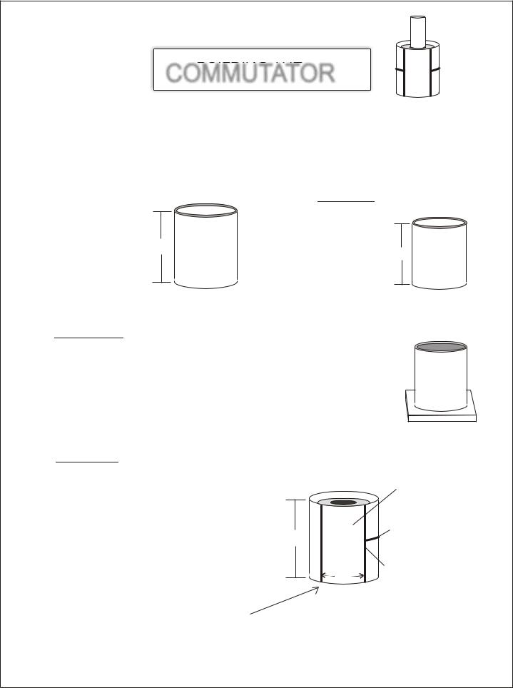
COMMUTATOR
OPTION ONE
This is a homemade Commutator designed by Rick and Dave, This DC Commutator is used to turn off the incoming DC voltage to the HV Voltage or Low Voltage Magnetic Coil. We are going to create a junction bar that rotates and as it rotates it will slide onto the 2 carbon DC motor brushes and cause a complete connection causing DC current to flow into the Electromagnetic coil.
We are going to give you 2 options in making a DC motor commutator. Pick which one is easiest for you.
STEP ONE
Cut a piece of 3/4” Diameter” x 1 3/8”
length copper pipe that
1 3/8”
you can buy at any hardware store.
Use a pipe cutter to cut a piece 1 3/8” long.
STEP TWO
Next using rough sand paper, sand the inside of the copper pipe
really good. And then
1 3/8”
clean with laquer thinner. Surface must be free from dirt.
STEP THREE
Using a Q-Tip, Grease a piece of card board a little larger than the copper pipe diameter, this is so the epoxy will not stick to the Card board surface and can be
removed when dry. You now need to fill the copper pipe with Epoxy, so slowly squeeze out enough J-B Epoxy to fill the inside of the copper pipe, follow all directions on the J-B Instructions, Mix the 2 parts very well and start placing the
epoxy inside of the copper pipe. Let dry 24 hrs, I prefer to wait 40 hrs, but the instruction do not tell you that. We use J-B Epoxy because it is the best on the
market and can stand up to 600 degrees.
Figure #3
STEP FOUR
Now you must find the exact center of the pipe and score it with a sharp punch. You will be scoring or punching a small hole into the top of the epoxy. Now you are going to need a drill press. Place the copper pipe up as you see in figure #3, Make sure bottom surface is very flat, if it is not the hole will be crooked and the commutator will ride with the shaft crooked and cause a off balance at high speeds. start off with the smallest drill bit you have and work your way up until you have a hole the same size as your shaft rods outer diameter.
STEP FIVE
Now using a fine point marker, mark your cut marks on the outside of the copper pipe piece. As shown in figure #4. Use a fine tooth hacksaw to cut.
Cut a long center cut all the way around the copper pipe leaving a 3/4” space. Cut all the way through the copper and just up to the hardened epoxy fill. Do not to deep into the epoxy fill.
Figure #4 |
Acts as a Junction Bar |
separates the brushes
from contacting each other. Cut all the way around pipe.
1 1/8” 
Use a very fine hacksaw blade to cut spacers, fill
3/4”
spacers with epoxy and sand smooth.
Fill in the cuts with epoxy, let dry 24 hrs then sand down until smooth. Now take a 5/16” steel shaft and place it back into the epoxy hole, now place a steel 5/16” shaft collar onto the steel rod and epoxy it to the end of your new commutator,
( remove the plastic end first. )
Page 19

Rick’s DC Motor / Generator |
# 362 |
C Copyright 2002 |
PART “F”
BRUSH HOLDER
ASSEMBLY
Cut two 1 5/16” x ½” x ½” x 1/16” Square steel.
|
T |
F” |
|
“ |
|
½” |
AR |
|
P |
|
1 5/16”
½” 

5/16” x 1/4” Motor Brush
J - B weld or PC 7 EPOXY
Plastic Separator
T |
F” |
“ |
|
AR |
|
P |
|
T |
F” |
|
“ |
|
|
AR |
|
|
P |
|
#2 |
|
|
#1 |
|
+ |
+ |
|
|
Copper holding Plate
PART “F”
PART “ G” |
1/4” |
PART “ G” |
2”
Fill with PC 7 Epoxy or J - B weld about 1/4” deep.
1 1/4”
Brush: grease brush and place inside of square steel part # “F”, Let sit and dry for 24 hrs, then remove brush and clean it off.
As an alternative to using brushes, you could replace with heat treated copper, which has some spring to it. Place the copper on part “ M “ and bend the copper upward.
+
+
Page 20

Rick’s DC Motor / Generator C Copyright 2002 |
# 362 |
PART “M”
Brush Assembly
HOLDING BAR
Use a 8 ½” x 3/4” x 1/16” or best to use 1/8” steel bar. This is used to hold the Brush Assembly.
3” BEND |
3” BEND |
PARTS “J” |
Plastic Screws |
& NUTS |
To attache Brush Assembly to holding bar.
PART “K”
ROLLER BEARING
Inner Diameter 5/16
You can buy these at Graingers.com
or from a skate shop.
2 ½”
Commutator
using copper pipe /J-B Weld
NOTICE: Place brushes in this position,
disregard the brush set up in the color
photo’s.
“ M “
t r a P
PART “N”
SHAFT COLLARS
To fit 5/16” D or buy one and drill it to size 5/16”
You will need a qty of two. The first shaft collar is to hold the shaft into place, allow a 1/8” space or more between collar and Part “D” The 2nd steel shaft collar is to be epoxied ( Glued ) to one end of the finished commutator.
Page 21

|
|
C Copyright 2002 |
# 362 |
PART “B” |
|
|
|
BASE LEGS |
|
Dril holes to: 7/64” |
|
|
|
|
|
3/4” 3 ½” |
3 ½” |
3 ½” |
|
|
|
|
5/8” |
12”
Aluminum 1/8”channel, check hardware stores, steel suppliers, lumber yards. Drill these holes at: Drill holes to 7/64”. You will need a qty of - 2. You will need to tap out each hole,
( Thread it ) using a 6-3 NC tap plug style.
PART “C”
ROTOR SHAFT
5/16” steel round rod
12”
1 7/8”
You will need three short pieces, two for the magnets to be used as spacers and one for a Shaft mold for making Commutator.
PART “D & E”
ROTOR SUPPORT ARMS
Use ½” aluminum bar. Check at: Machine shops, Steel suppliers in your Yellow Pages, Steel salvage yards etc... Drill two holes on each arm, use a 5/16” drill bit. After you install roller bearing assembly on part “ D “, remove roller bearing and drill a bigger hole using a 11/32” drill bit. On Part “ E “ Drill only halfway through, so the 5/16 rotor shaft can turn on it.
Part “ D “ |
|
|
|
|
|
|
|
|
|
Part “ E “ |
||||||
|
Center |
|
|
|
|
|
|
|
|
|
|
|
Center |
|||
|
|
|
Roller bearing assembly, Use a large steel washer, assemble this after you put |
|
|
|
|
|
||||||||
|
|
|
|
|
|
|
|
|||||||||
|
|
|
the Rotor shaft and arms together Once your shaft is running through Part “ D “ |
|
|
|
|
|
||||||||
|
|
|
hole, you can then place the Roller bearing onto it. Grease the outer part of the |
|
|
|
|
|
||||||||
|
|
|
bearing, Predrill 2 or 3 holes |
in the large steel washer, place the large washer |
|
|
|
|
|
|||||||
|
|
|
over top of the roller bearing, |
|
center |
and mark |
your holes, use a 7/64” drill bit |
|
|
|
|
|
||||
|
|
|
and tape out your holes with a |
6-3 NC tap, then |
attach the washer to Part “ D “ |
4 1/4” |
||||||||||
|
3 11/16” |
with 6-32 x1 ½” bolts. Now mix |
up |
some |
J-B weld or Pc7 Epoxy and fill the |
|||||||||||
|
inside beneath the washer |
and |
all |
around |
the |
roller bearing. ( Make sure |
|
|
|
3 11/16” |
||||||
|
|
|
bearing is greased well so |
you |
can |
remove it |
to later drill your larger hole. |
|
|
|
|
|
||||
|
|
|
The reason you need to |
dril l a larger |
hole later is so your rotor shaft can turn |
|
|
|
|
|
||||||
|
|
|
more easily. Let epoxy |
dry |
|
for |
24 hrs, then remove your Steel washer roller |
|
|
|
|
|
||||
|
|
|
bearing plate, then remove your roller bearing, drill a bigger hole in Part “D” then |
|
|
|
|
|
||||||||
|
|
|
place you bearing back onto the molded roller bearing assembly. |
|
|
|
|
|
||||||||
|
|
|
|
|
|
|
|
|||||||||
|
2 ½” |
Part“D“ |
Part“E“ |
½”
2 ½”
Page 22

Rick’s DC Motor / Generator |
Copyright 2002 |
# 362 |
|
|
|
This is a research device, Capacitor and diode ratings depend on the voltage input |
vs what size coil wire used and # of winds. |
|
If you use a coil that is wound several thousands of times with number 38 or 36 copper coated wire, you are going to need to use voltages from 1000 to 3,500 vdc input. The back emf will be great. # 38 wire is hair thin and hard to wind but it is the best to use for a PVC air core type magnet.
+
Example:
2000 - 3,500 vdc input for air cores
120 to 600 volts for iron cores.
|
|
|
|
|
|
|
|
Switch represents the On / Off Commutator and brushes |
|
|
|
|
|||
Using # 36 or 32 copper coated wire is much easier to |
|
|
|
|
|
|
|
|
|
|
|
|
|
|
|
|
|
|
|
|
|
|
|
work with. Make several coils out of old transformer iron |
|
|
|
|
|
|
|
cores. You will need to do a little cutting. This will be a |
+ |
|
|
|
|
|
|
great learning experience for you when you go to build |
|
|
|
|
|
||
a larger unit. Make one coil with #18 copper coated |
|
|
|
|
|
|
|
wire which should come out to be about 90 to 100 turns, |
|
|
|
|
|
|
|
you will notice that free energy can be collected but |
|
|
|
|
|
|
|
the coil and commutators run hot, heat loss = energy |
|
|
|
|
|
|
|
loss. |
|
|
|
|
|
|
|
# 18 wire will take voltages from 12 to 24 vdc. |
|
|
|
|
|
|
|
#38 wire will take voltages from 200 to 3,500 vdc. And |
|
Output to load or back to battery |
|
||||
will run very cool and use very little amperage from your |
|
|
|||||
|
|
|
|
|
|
|
|
DC power supply, use a 12 vdc battery with a small 100 |
|
|
|
|
|
|
|
|
|
|
|
|
|
|
|
watt dc to ac inverter. |
|
|
|
|
|
|
|
|
|
|
|
|
|
|
|
|
|
|
|
|
|
|
|
Page 23

Page 24

Rick’s DC Motor / Generator
PART “P”
COPPER COATED
Magnetic Wire
You will need 3 different rolls of wire.
#16 or #18 gauge, # 26 or close to,
#36 or # 38 hair thin wire.
C Copyright 2002 |
# 362 |
You will need Copper coated wire to wrap around your soft Iron Cores, You will want to build up to 4 different Electromagnetic Coils with different size wire for study and research purposes. Teachers show your students the different effects and outputs that this Motor Generator will make by using more turns of wire vs less turns and the wire size. Make your Magnets interchangeable. Collect the Back Emf to and use the Vortex Effect to show your students how to get Free Energy out of there motors.
|
Use #16 gauge or #18 Gauge copper coated wire to make a |
+ |
Spiral. demonstrates an amperage hog motor, Place this Spiral |
under the motor shaft. Run test and note what happens. |
|
|
To make a Spiral coil, use two pieces of flat plexi glass or MDO |
|
board, drill a center hole in both, sandwich the 2 pieces together |
|
leaving a metal or cardboard spacer in between the 2 boards, |
|
the spacer washer must be the same size thickness as the wire. |
|
Now place a bolt in the center hole and attache a nut. |
_ |
Now drill a small hole nest to center hole so you can run the first |
part of your wire through, tape it down and begin turning wire. |
Reversing polarity reverses the poles.
Produces a strong magnetic force without the use of a middle soft iron core!
PART “Q”
CERAMIC MAGNETS
North
North
For this motor you will need 2 powerful ceramic permanent magnets, you can buy these from Radio Shack or search the internet for magnet suppliers. If you want to increase your horsepower then you must add more magnets to your shaft, on this motor you can get 2 pair. Make sure to redesign your magnetic coil structure to be longer. You can also design a large HP motor with Radio shack magnets by buying a hex shaped metal rod, 
 and glueing 24 magnets to it. This will also
Insure that your permanent magnets will last a very long time.
|
S |
|
S |
S |
For the more advanced: Use a aluminum or steel Hex Bar, have a |
machine shop round off the ends to fit your end bearings. Epoxy |
||
|
1” |
each magnet onto the hex bar. Example length, 18 3/8” long. |
|
|
|
|
|
Use 1” hex flats. This will make for a very powerful free energy |
|
|
motor. |
N |
N |
|
N |
Page 25 |