

Phedotikov / 1 / FreeEnergy_27.01.08 / Гравитационные / Энергия гидротарана / The Folk Ram Pump
.pdfThings that Work!
Things that
Work! |
tested by Home Power |
|
Things that Work! |
The Folk Ram Pump
Michael Welch
©1994 Michael Welch
Tested by Michael Welch, Cara Smith and classmates of Humboldt State University’s International Development Program (Susan Brinton, Christopher Herbst, Christine Parra, David Potter, Jon Raybourn, Dav Camras, Daniel Oros, Mike Orr, and Wallapa Wongsuwan).
The Site
Cara Smith of Fieldbrook, California had a problem. Every year in August, her spring flow reduces to a mere trickle. As the Northern California drought got worse year after year, so did her spring’s ability to supply her household needs. She needed a permanent solution to her problem.
Fortunately, a nice creek crosses Cara’s property, and it flows year round. But, it is 360 feet in elevation below
her water storage tank, which gravity feeds to her home. I had been looking for a site to adequately test the Folk ram pump, and this seemed like it would work. I had been attempting to test the pump on my own system at my home. While it worked well enough for me, my flow was too small to really put the pump through its paces.
So what is a ram pump anyway? Ram pumps use a downhill water pressure to pump a portion of that water even higher uphill to a holding tank. No other source of power is needed.
We enlisted the help of HSU’s International Development Program to design, build and test the ram pump system. But that’s a story in and of itself that we may tell in a future HP article. For now, suffice it to say that this academic program prepares students to help third world countries with their development requirements, and strongly emphasizes appropriate technology to meet these countries’ needs.
The Pump Arrives
When I received the Folk ram, I was surprised to see that it was in pieces. Normally, Jim Folk ships his pumps completely assembled, ready to install. But, Jim knew that I was very interested in the workings of his pumps, so he sent it to me disassembled, with a labeling tag on each component explaining the why’s and the how’s of its design and use. I really appreciated that, but any other customer can expect the pump to arrive well-packed and already assembled.
44 |
Home Power #40 • April / May 1994 |
Things that Work!
His largest pump, however, is too heavy to ship by UPS, so it comes in two pieces easily bolted together.
This pump is heavy-duty. Its body is thickly cast and machined from high-grade aluminum alloy, and the inner components and the bolts make use of stainless steel. The internal “valves” are made of thick, bonded rubber seals.
A feature of the Folk ram not found in most ram pumps is a strong rubber diaphragm which separates the delivery water from the pressurized air chamber. This diaphragm keeps the air from mixing and exiting with the delivery water, thus eliminating the need for a “snifter valve” to replenish the air chamber.
Other features of the Folk ram pump include larger- than-usual impetus and check valves for faster reaction time and a large air dome to minimize delivery water pressure pulsations and thus decrease friction loss. The impetus valve stroke length is easily adjustable to change the frequency of pump cycles, which changes the amount of water the pump uses and delivers.
Installation
The Folk ram arrived with adequate instructions on how to install, maintain and run it, but there is some room for improvement. Jim Folk told me that he wanted to do a better and more detailed manual for the pump.
One great thing about Jim Folk is that it is as important to him that the pump works well as it is to sell the pump in the first place. If you have problems with your installation or operation, he will work with you in detail. It’s just how he is, and most people can really appreciate it. For example, there was a problem with the bonded rubber the pumps used in their valves. When Jim discovered the defect, he automatically sent every pump owner a new set of valves, using improved materials, and he did it free of charge.
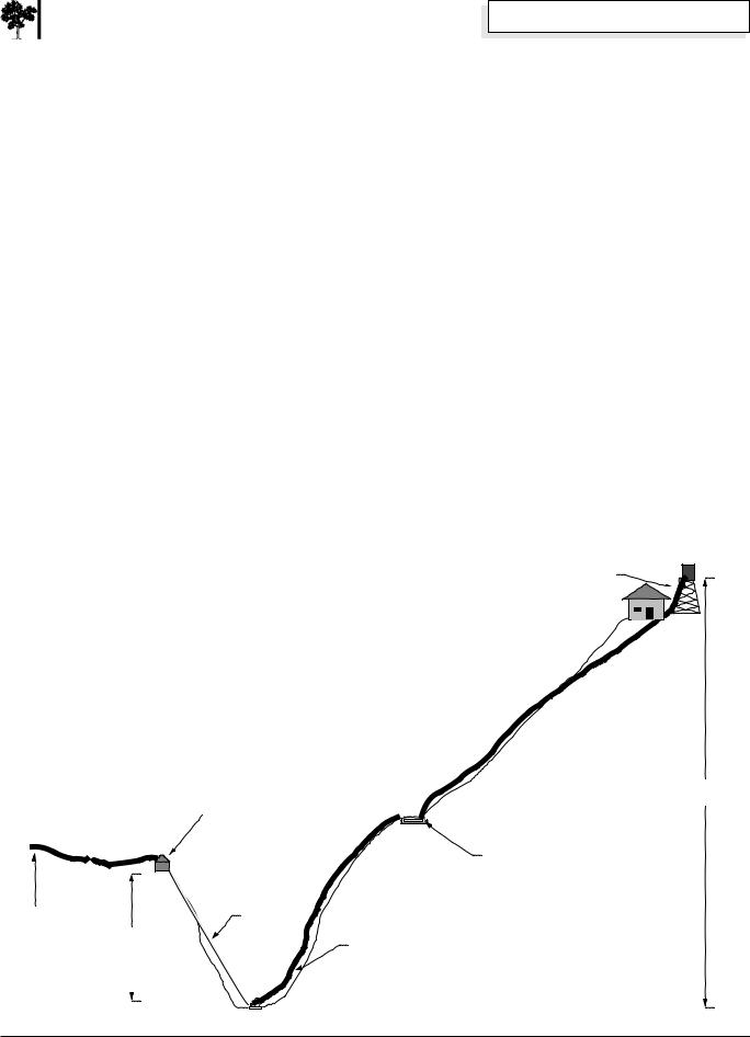
Long distance water pumping systems have so many variables that every installation is different. In our case, the terrain was very steep and somewhat rugged. In order to get adequate vertical drop to run the pump, we had to snake the supply pipe 420 horizontal feet from the source to a settling tank, and then go steeply down the hillside to the pump site with the drive pipe. The cost of having to run such a long horizontal distance was a reduced supply available to the pump. While Cara’s creek flows at about 72,000 gallons per day, our 420 feet long, two inch diameter supply pipe with five feet of head between the creek inlet and the settling tank would make 5,400 gallons per day available to the pump.
Most installations will be more straightforward than ours, and less expensive as a result. The price of the
Cara's Water Delivery System |
Storage Tank |
Settling Tank to Storage Tank |
(500 gal.) |
(not to scale) |
|
Supply line from creek weir
Pump Head 45'
45'
(Under ground)
Settling Tank
(300 gal.)
Conduit (under road) (20 ft.)
Drive Pipe
(120 ft.)
Delivery Pipe
(1300 ft.)
Delivery Head |
360' |
Ram Pump
Home Power #40 • April / May 1994 |
45 |
Things that Work!
1 |
2 |
air |
delivery |
|
|
||
|
|
pipe |
|
|
|
water |
|
drive |
air |
|
|
|
|
||
pipe |
water |
|
|
|
|
|
|
|
|
|
pressure |
|
|
|
valve |
3 |
4 |
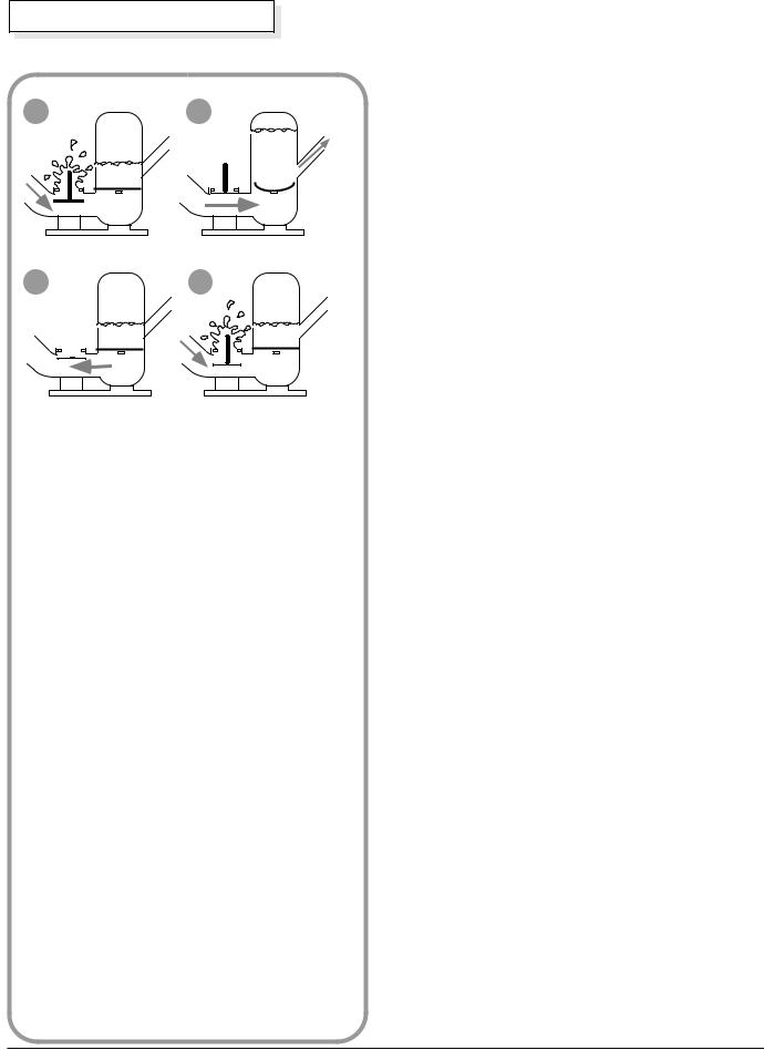
impulse valve 

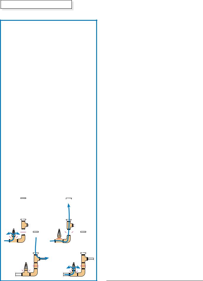
How a Ram Pump Works
All ram pumps work on the principle of momentum which is controlled by a cycle set up by the interaction of two valves in the pump.
When the impetus valve is opened (this must initially be done by hand to start the pump cycling), water begins to flow down the drive pipe and through the impetus valve as in Figure 1. When the drive water reaches a certain velocity, water friction slams shut the impetus valve as in Figure 2. The momentum of the water carries past the closed impetus valve, forcing open the flapper valve and pushing water past it to pressurize the air chamber above the water level. In Figure 3, the water pressure above the flapper valve overcomes the spent momentum below it, forcing the flapper closed again. The water that made it past the flapper in Figure 2 is then forced by the extra air pressure up the delivery pipe. Since the momentum of the water coming down the drive pipe was stopped, the impetus valve falls open, allowing the water to flow down the drive pipe again as in Figure 4 (just like Figure 1), starting the cycle over again.
This process occurs over and over again until something happens to stop the cycle. Ram pumps can cycle anywhere from 25 to 300 times per minute. The frequency of the cycle is adjustable by changing the length of the stroke of the impetus valve. A longer stroke produces a lower frequency. This means more of the supply flows to and through the pump and more is pumped up the delivery pipe.
The stroke is adjusted to restrict the amount of water used to the amount available, or if supply is unlimited, to regulate the amount delivered to match the amount needed.
pump remains a fixed cost for everyone, but the installation costs can vary widely. Because of the long supply line and the uncommonly high delivery elevation, Cara’s installation costs were about double the average installation. I estimate the average to be about $1,000 for system components including the Folk ram pump which runs about $695. Labor is not included in these approximations.
A typical installation includes a 1.5 inch steel drive pipe from the source to the ram pump, a poured concrete foundation to secure the pump, a one inch poly delivery pipe to the household supply tank, and valves and unions to control flow and allow access to the various components of the system.
Pump Performance
Because the Folk ram’s capabilities could easily outstrip our supply, we choked it back so it wouldn’t run out of water. When a ram pump stops cycling, it needs to be restarted by hand. Once we had the pump properly set, it just kept running on and on for months without the need for further attention. This reminds me of a ram pump story I heard:
Friends were hiking near the New River in the Trinity Mountains of Northern California. This river is peppered with old gold mining claims. Far away from any other form of civilization, the hikers were surprised to come to an otherwise pristine spot where they heard a muffled “ka-chunk ka-chunk ka-chunk....” Taken by surprise, they were unable to discover the source of the mechanical noise until they dug down several inches through the forest humus finding a rotten board covering a hollow box. The box contained an old ram pump that had been operating on its own, unattended for as long as it took the box cover to become buried under many layers of duff.
Commercial ram pumps are known to provide years of trouble-free service. We expect that the Folk ram will furnish Cara with water for decades to come.
Even with the pump choked back for the decreased supply, we obtained delivery rates of 600 gallons per day. This is a far cry from the 2,400 gallons per day that this pump could achieve under the same drive and delivery heads with unlimited access to the creek’s supply. However, it was more than adequate for Cara’s needs which max out at 475 gallons per day. Jim Folk states that, under ideal supply, drive, and delivery conditions, this particular model of his pump will produce up to 5,000 gallons per day. He has a second model that will produce up to 25,000 gallons per day.
For you folks with super low flow situations, this pump may still work for you. For several months, I had this
46 |
Home Power #40 • April / May 1994 |

Things that Work!
pump installed on my own spring which was flowing at about 1,500 gallons per day, with 26 feet of drive head, and 158 feet of delivery height. This is really running the pump on the low end of its capabilities, yet it still was able to provide my home with about 190 gallons of water per day.
Conclusion
Folk ram pumps are well-made, dependable, and work as promised. While there are other ram pumps available, the Folk has features that are unique and proven. At $695 for a pump that will likely outlast its owner, it is an excellent buy. A larger model is available that lists for $995. These pumps are handmade in Conyers, Georgia.
Access
Author: Michael Welch, c/o Redwood Alliance, POB 293, Arcata, CA 95521 • voice 707-822- 7884 • BBS 707-822-8640
Ram Pump Maker: Folk Water Powered Ram Pumps, 2770 White Court N.E., Conyers, GA 30207 • 404-922-4918
Trace Engineering
camera ready
4.68inches wide
4.85inches high
We |
Specialize |
Home & Cabin |
|
Solar Electric & Heating Systems
— 18 years of Cold Climate Applications —
— Design /Build or Licensed Installs —
Off |
• Kyocera, Solarex, and Siemens Modules |
|
|
||
15% |
• Trace Inverters and Ananda Power Centers |
|
These |
• Wir’sbo Radiant Floor Tubing |
|
Products |
||
|
||
Spring |
• Whisper 600 (World Power Tech) Wind Machine |
|
Thru |
||
|
Solar |
SDESS |
Designed |
P.O. Box 36, Crosby, MN 56441 |
Energy |
|
Systems |
218-546-5369 |
& |
|
Services |
*Seminar Dates in Mpls & St. Paul — Call |
|
 N E O +2™
Exclusively from AMERICAN INDEPENDENT POWER
1-800-DCSOLAR
Spring Wind Blow-out! $850 (STD)
UP TO 1000W @ 30 MPH
+2 Does more! Regulates all your charging sources! Switches to aux load at full charge. Choice of Voltage NEO+2 w/compl wired board $975
NEO Star (w/wired board & 1500 PowerStar $1775) Call for other Spring Blow-outs!!!
Energy independent, established since 1974
American Independent Power
60 Firehouse Road, Plymouth, MA 02360 • 508-759-6706
Home Power #40 • April / May 1994 |
47 |
|
|
|
|
|
|
|
|
|
|
|
|
|
|
|
|
|
|
|
|
Scott Lee |
©2000 Scott Lee |
|||
uring the mid 1970s, I first Dencountered the hydraulic ram
water pump. A friend of mine was interested in a water pump for irrigating a garden. I had also purchased some land with a stream and a nice garden spot, but no electrical service. The combination of a stream below my garden spot and no electrical power seemed to be a perfect situation for a hydraulic ram.
Three Tries
The manufactured rams back in the ‘70s were fairly expensive—US$250 and up. Some publications had home-built designs. One in particular was by an organization called VITA (Volunteers in Technical Assistance). Based on the cost of the manufactured rams, I set out to construct a home-built ram pump. The first two versions of my ram were based loosely on VITA’s descriptions and plans. They weren’t followed
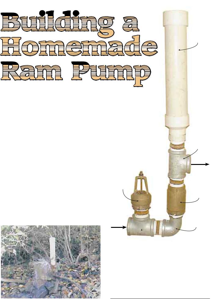
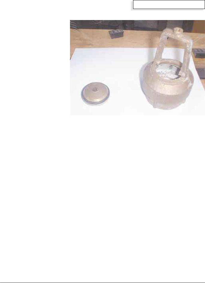
Scott Lee’s ram pump in operation.
Air chamber
Tee
Out to delivery pipe
Foot valve (modified)
Check valve
Street elbow
In from drive pipe
Tee
exactly, due to the difficulty in obtaining some of the parts that were mentioned.
I recently went to the local hardware store to check out the cost of these parts. The 2 inch version of my homebrew ram will cost about US$130 (see parts list). A 1 inch ram will be cheaper, and might cost a little more than half that amount. The cost of the pipes needed to hook up the ram may exceed the cost of the ram itself.
42 |
Home Power #76 • April / May 2000 |
Ram Pump Parts List
Qty |
Item |
1 |
2 inch foot valve (brass) |
1 |
2 inch check valve (brass) |
2 |
2 inch tees (galvanized) |
|
|
6 |
2 inch close nipples (galvanized) |
1 |
2 inch street elbow (galvanized) |
1 |
2 by 1 inch bushing (galvanized) |
|
|
1 |
1 inch close nipple (galvanized) |
1 |
3 inch pipe cap (PVC) |
1 |
3 inch pipe, 18 inches long (PVC) |
|
|
1 |
3 by 2 inch reducer (PVC) |
1 |
2 inch PVC to IPT adapter (PVC) |
1 |
1/4 inch threaded rod (stainless) |
|
|
6 |
1/4 inch nuts (stainless) |
2 |
1/4 inch washers (stainless) |
1 |
Faucet washer |
|
|
1 |
14 gauge copper wire, 2 inches |
The first version of my ram was built entirely out of galvanized steel pipe and fittings. The waste (or impetus) valve proved to be the hardest to construct. The first version’s valve was constructed from a 1 1/2 by 1 inch bushing. While this valve worked after a fashion, it was very leaky. I figured that the ram would perform better if this valve would seal tightly. My second version had a valve that was constructed from a 1 1/2 inch pipe plug. The plug was bored with a 1 inch hole, and had the inside surface of the plug machined smooth. This resulted in better ram performance.
I never used the first two versions in working applications, though I did test them. Shortly after the second one was operational, an article appeared in The Mother Earth News (May/June 1979, #57, page 120) with instructions on how to build a ram mainly out of PVC pipe fittings. Using this design as a guide, I developed a third version. This version was also built from galvanized steel pipe fittings, with the exception of the air chamber, which was constructed from PVC pipe
Homebrew
and fittings. This version still required machining of a sort—cutting threads on the outside of a 1 1/2 inch hose barb, so that it would thread into a 2 by 1 inch bushing.
Although this was a workable system for constructing the waste valve, it still was not as simple as I wanted. For a time, this ram was used to pump water to my garden. The water was also used to provide showers, with
Delivery
the use of 200 feet (60 m) of 3/4 inch black head poly pipe for a solar water heater. This pump
was installed with a 4 foot (1.2 m) fall (head) to the ram, developed over the distance of 100 feet (30 m). It had a delivery lift of 30 feet (9 m) to a 3 by 12 foot (0.9 x 3.7 m) pool used as a storage tank. The point of use was 15 feet (4.5 m) lower than this storage pool.
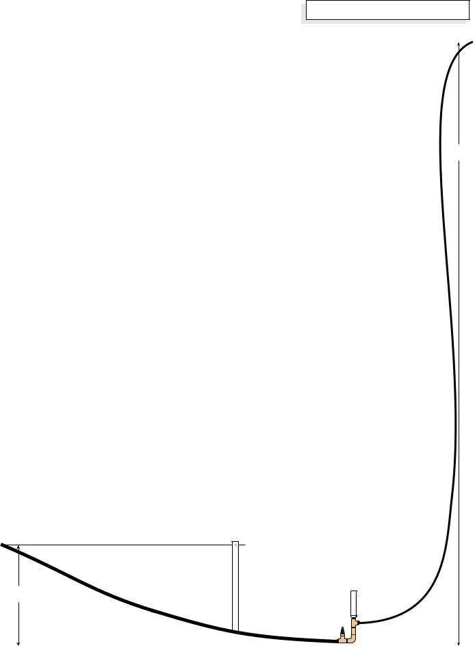
Standpipe
When the ram was first put into service, it operated very slowly—about 15 to 20 cycles per minute. Everything that I’d read stated that rams of this size should operate at about 45 to 60 cycles per minute. I fabricated a standpipe and inserted it in the drive line about 30 feet (9 m) from the ram. This is within the recommended 5–10 times ratio of head to drive pipe length. This allowed the ram to operate in the 45 to 60 cycles per minute range. The flow of water delivered to the tank increased from 0.25 to 0.75 gallons (0.9 to 2.8 l) per minute.
Ideally, the length of the drive pipe should be in the range of 5 to 10 times the head. So for a head of 3 feet (0.9 m), the length of the drive pipe should be in the range of 15 to 30 feet (4.5–9 m).
If the drive pipe is too long, the cycle frequency that the ram can operate at will be limited to some low value. The standpipe provides a closer location for the ram pump’s supply. This means that there is less resistance in the drive pipe, and the flow can reach full velocity more
Water supply
Standpipe
(optional)
Supply |
Supply |
head |
pipe |
Drive |
Ram |
Delivery |
pump |
pipe |
|
pipe |
|
|
|
|
|
|
|
|
Home Power #76 • April / May 2000 |
43 |
||||
Homebrew
How a Ram Pump Works
The energy required to make a ram lift water to a higher elevation comes from water falling downhill due to gravity, as in all other water-powered devices. But unlike a water wheel or turbine, the ram uses the inertia of moving water rather than water pressure, and operates in a cycle.
1.When the waste valve is opened, water flows from the source, through the water inlet (drive) pipe, and out the waste valve.
2.After a short time, the velocity of the flow is high enough to force the waste valve closed. The water, due to its inertia, wants to continue moving past the valve. The pressure inside the ram will rapidly increase enough to force the check valve open. This forces some water into the air chamber, compressing the chamber’s air bubble. The pressurized bubble forces that water through the delivery pipe to the point of use.
For a ram pumping one gallon (3.8 l) per minute, and cycling 60 times per minute, each cycle pumps onesixtieth of a gallon—about two ounces (60 ml). The compressed air in the air chamber helps smooth out the flow on the delivery side of the ram, so the flow tends to be more continuous, rather than a small spurt during each cycle of the ram.
3.Soon after the check valve has opened, the pressure surge (generated by the waste valve closing) is spent. Flow will try to start backwards, but the check valve will close, preventing this from happening.
4.At about this time, the pressure in the drive pipe will be low enough so that the waste valve can open, allowing water to start flowing from the source to the ram, beginning a new cycle.
The cycle that the ram goes through can occur 30 to 120 times per minute, depending upon conditions such as head, flow, and the size of the ram.
|
1 |
|
|
|
2 |
|
|
|
|
|
|
||||||||
|
|
|
|
|
|
|
|
|
|||||||||||
|
|
|
|
|
|
|
|
|
|
|
|
|
|
|
|
|
|
|
|
|
|
|
|
|
|
|
|
|
|
|
|
|
|
|
|
|
|
|
|
|
|
|
|
|
|
|
|
|
|
|
|
|
|
|
|
|
|
|
|
|
|
|
|
|
|
|
|
|
|
|
|
|
|
|
|
|
|
|
|
|
|
|
|
|
|
|
|
|
|
|
|
|
|
|
|
|
|
|
|
|
|
|
|
|
|
|
|
|
|
|
|
|
|
|
|
|
|
|
|
|
|
|
|
|
|
|
|
|
|
|
|
|
|
|
|
|
|
|
|
|
|
|
|
|
|
|
|
|
|
|
|
|
|
|
|
|
|
|
|
|
|
|
|
|
|
|
|
|
|
|
|
|
|
|
|
|
|
|
|
|
|
|
|
|
|
|
|
|
|
|
|
|
|
|
|
|
|
|
|
|
|
|
|
|
|
|
|
|
|
|
|
|
|
|
|
|
|
|
|
|
|
|
|
|
|
|
|
|
|
|
|
|
|
|
|
|
|
|
|
|
|
|
|
|
|
|
|
|
|
|
|
|
|
|
|
|
|
|
|
|
|
|
|
|
|
|
|
|
|
|
|
|
|
|
|
|
|
|
|
3 |
4 |
quickly than without the standpipe. Basically, a standpipe allows the ram to operate as if it had a shorter drive pipe.
The diagram on page 43 shows a standpipe inserted between the supply pipe and the drive pipe. The critical distance is now only the distance between the standpipe and the ram, not the total distance to the source of supply.
A standpipe can easily be constructed out of PVC pipe and fittings. The pipe needs to be long enough so that it is a few inches higher, in its installed location, than the elevation of the water source. Consider screening the top of the standpipe to keep out birds, insects, and detritus if you are pumping potable water.
The standpipe is usually inserted at a distance from the ram that is 5 to 10 times the supply head. This will vary from installation to installation. Since my installation had 3 feet (0.9 m) of supply head, I inserted the standpipe 30 feet (9 m) from the ram. This allows the ram to cycle properly, which results in more water pumped.
It’s also important to consider the diameter of pipe on long drive runs, to minimize flow loss due to pipe friction. When in doubt, go up in size. It’s recommended that the standpipe be at least two full pipe sizes larger than the drive pipe. I’ve used 4 inch standpipes with 2 inch rams, and 2 inch standpipes with 1 inch rams. It’s also recommended that the pipe from the supply to the standpipe be one full pipe size larger than the drive pipe. This will insure that the flow to the standpipe will be able to keep up with the ram pump’s usage.
Drive Pipe
This configuration operated for about six months, after which it was dismantled for the winter. It was later installed at a new location with 3 feet (0.9 m) of head and 12 feet (3.7 m) of lift. Most of the time it supplied garden soaker hoses, with an old 52 gallon (200 l) hot water tank being used for a small storage volume, operated as a pressure tank.
One day, we were operating the ram with the discharge valve shut, and we noticed that the 2 inch black poly drive pipe was actually expanding visibly with each closing of the waste valve. We concluded that a portion of the energy was being wasted expanding the drive pipe, rather than pumping water. We also noticed that the max discharge pressure was 21 psi.
So I replaced the 30 feet (9 m) of black poly pipe between the standpipe and the ram with schedule 40 PVC pipe. With this pipe in place, I noted that the maximum discharge pressure was now 57 psi. This meant an almost threefold increase in the amount of water delivered. With a 12 foot (3.7 m) lift, we
44 |
Home Power #76 • April / May 2000 |
measured the flow at 2 gpm after the installation of the PVC drive pipe.
Based on these observations, I suggest that you don’t use black poly pipe or other flexible pipe for the drive pipe. If you are using a standpipe, the pipe from the standpipe to the ram is the only section that needs to be rigid. The supply pipe from the source to the standpipe can be flexible. If your drive head is higher than a few feet, steel drive pipe is recommended, since high pressures can blow out plastic pipe joints.
Versions Four & Five
Although this ram was successful, it still was not completely satisfactory. The waste valve needed a lot of maintenance, and also required a pipe threading machine to make it.
In light of these shortcomings, a fourth version was built using a standard plumbing check valve for the basis of the waste valve. This worked well, but required a lot of work to cut discharge ports into the check valve.
In a matter of days after version four was put in operation, it was discovered that a foot valve would serve the purpose as well as a check valve, with very little work required to convert. This valve was built and put into operation successfully and performed well. The fifth version is still in use. I think that it was first used in 1980 or ‘81. This ram continues to provide irrigation for a garden, and water for keeping a compost pile moist enough for proper decomposition.
It should be noted that this is not a year-round installation. Before winter weather starts, the ram and standpipe are removed from the stream to prevent freezing. They are reinstalled the following spring. This has worked well, since there is no demand for the water during the winter.
I built and installed another ram of this size for a neighbor, to supply water from a spring to two houses. This ram was a slightly improved version. The main differences were that I used a larger check valve and foot valve, which improved the performance slightly. This ram was supplied by 4 feet (1.2 m) of head and lifted the water 30 feet (9 m) to a 1,500 gallon (5,700 l) storage tank about 1,400 feet (425 m) away.
At the storage tank, separate centrifugal pumps and pressure tanks were used to supply water to both
Home Power #76 • April / May 2000 |
45 |
Homebrew
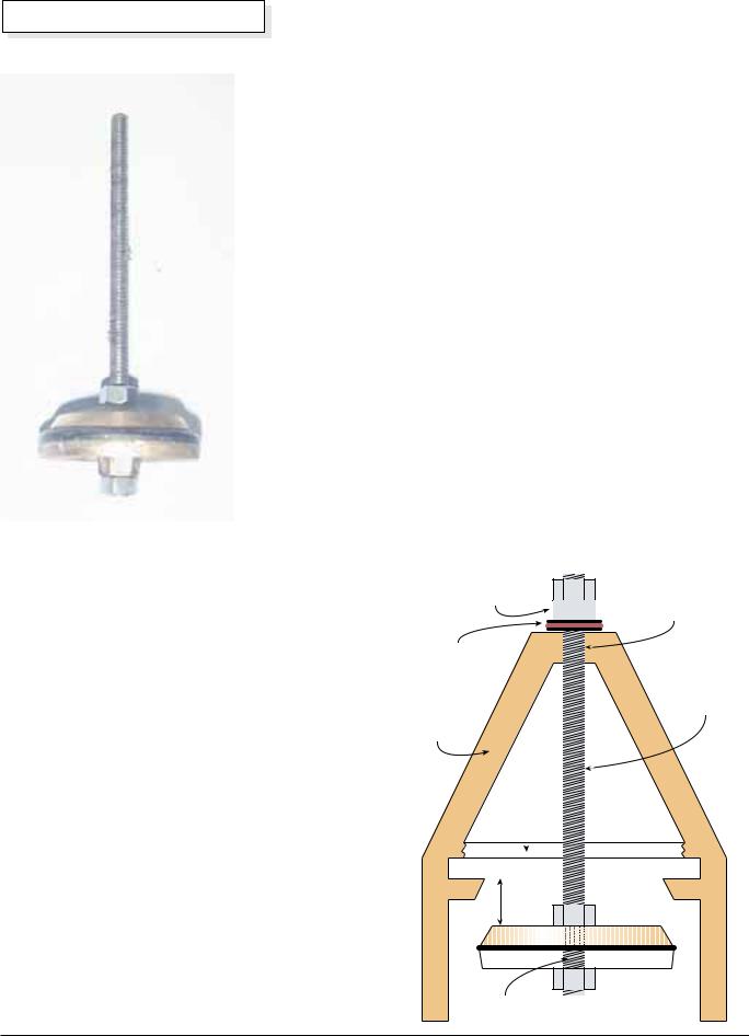
The valve disc is reassembled with a 6 inch long piece of 0.25 inch stainless steel threaded rod, and locked in place with nuts top and bottom.
Now take the valve body and enlarge the threaded hole in the top crosspiece to 1/4 inch with a drill. Again, use care to get this hole straight. Using a hacksaw, remove the lower crosspiece.
After these modifications have been made, take the modified valve disc and insert it up through the valve body. After you have inserted it, put on a 1/4 inch washer, a faucet washer with its hole enlarged to 1/4 inch, and another 1/4 inch washer. The faucet washer provides some cushion to help quiet the waste valve when it falls open. Then thread on two 1/4 inch nuts, adjusting them so that they allow about 1/2 inch (13 mm) of movement of the valve disc and stem within the body. This is a good starting point—further adjustments can be made later, after the ram is operating. Your assembled valve should look like the diagram at right.
Air Sniffer
The next step is to modify the 2 inch check valve by adding an air sniffer hole. This hole will allow a little air to be taken in on each stroke of the ram, replacing air in the air chamber that has dissolved in the water and gone up the delivery pipe. Loss of all the air in the air chamber can result in something breaking. I once saw the bonnet of a 2 inch PVC valve blow off. This valve was used to isolate the ram from the drive pipe. If you choose not to use an air sniffer, you must shut down the
ram every few days and drain some water from the air chamber.
Begin the construction of the air sniffer by stripping the insulation from a piece of #14 (2 mm2) copper wire. Select a drill bit that is just slightly larger than this wire. Use this bit to drill a hole in the check valve as shown in the next sketch.
Make sure that you drill this hole on the correct side of the valve seat, as shown on page 47. After you have drilled this hole, twist a small loop in one end of the wire you have stripped. Insert the straight end of this wire into the hole, and twist another small loop in the wire on the inside of the check valve. If you are building the ram for a low-head installation, you may want to remove the spring from the check valve at this time. Otherwise it can be left in place.
Air Chamber
The air chamber is the last piece you will need to assemble before the ram can be completely finished. A 4 inch diameter air chamber should be okay for up to 10 feet (3 m), while a 6 inch chamber should work for about 15 feet (4.5 m). When in doubt, it’s probably better to err on the large side. The air chambers are usually about 18 inches (46 cm) plus the length of the fittings, but could be made longer if necessary.
Assembled Waste Valve Detail
Stainless steel nuts
1/4 inch Casing drilled to accept rod
Washers
Stainless steel threaded rod
1/4 inch by 6 inches
Foot valve casing
Lower crosspiece removed
1/2 inch travel
Valve disc drilled to accept rod
46 |
Home Power #76 • April / May 2000 |
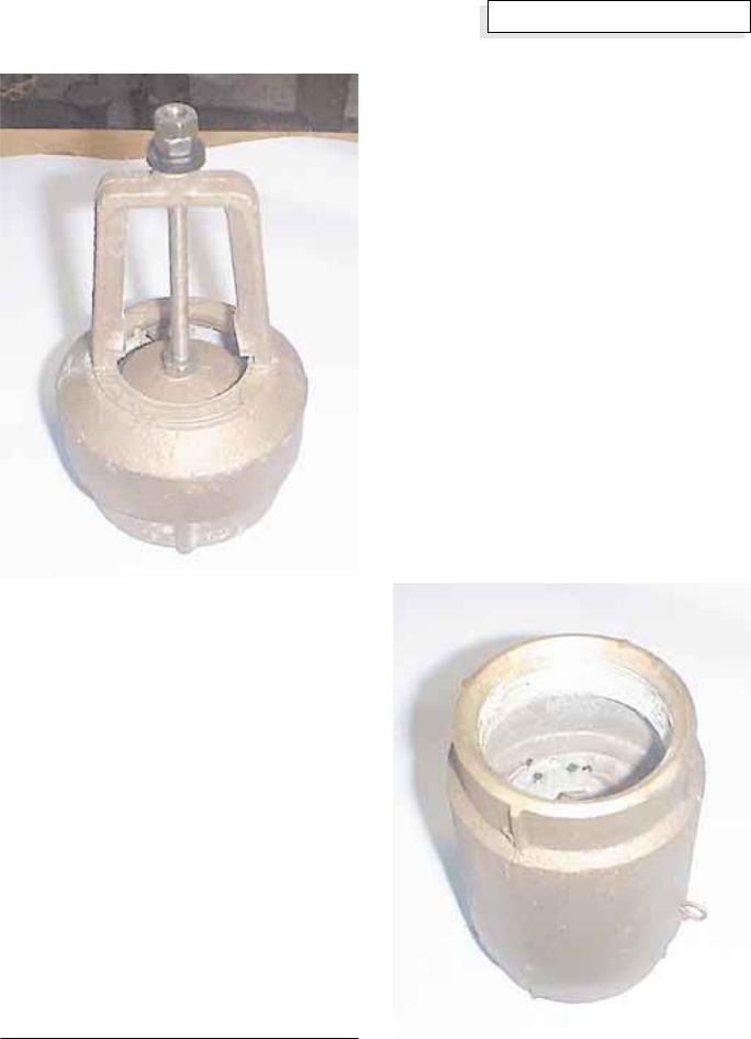
The modified foot valve ready to assemble onto the ram.
To assemble the air chamber, glue a cap to one end of the 3 inch PVC pipe. Then glue the 3 by 2 inch reducer to the other end of the pipe. After these are complete, glue in the PVC to IPT adapter. The air chamber should now be complete, and the final assembly of the ram can proceed.
Assembly
Screw a 2 inch close nipple into one of the end branches, and another into the side branch, of a 2 inch tee. Teflon tape should be used on all of the threaded connections. This will aid in any disassembly that may be required in the future. Screw your waste valve onto the nipple on the tee’s side branch.
Screw the street bend onto the nipple on the end branch. Screw the check valve onto the end of the street bend. The flow directional arrow should point away from the street bend. Screw a 2 inch close nipple into the check valve. Screw an end branch of the other 2 inch tee onto the close nipple.
Screw another close nipple into the other end branch of the 2 inch tee. Screw your air chamber onto this nipple. Screw the 2 by 1 inch bushing into the side branch of
Homebrew
the tee. Screw the 1 inch close nipple into this bushing. Go back to the first 2 inch tee and screw in the last 2 inch close nipple.
Your completed ram should look approximately like the photo on page 42. The 3 inch air chamber size on this ram should be adequate for supply heads of up to 5 feet (1.5 m). If the head is greater than this, the air chamber should be larger.
Installation
This completes the ram pump construction, but you may find that this is the easiest part of the job. As much or more depends on a good installation. I recommend that you use a union on either end of the ram. A gate valve on both the drive and discharge lines will also facilitate any maintenance that is required on the ram itself. The diagram on page 43 is a typical ram installation, showing head, lift, supply, delivery, and the length of the drive pipe.
To calculate how much a ram will deliver, divide the head by the lift, multiply by the flow, and finally multiply by 0.6. It takes at least 5 gpm to run this ram, with at least 2 feet (0.6 m) of head. In general it is easier to pump more water with more head, so run more drive pipe to get the head you need.
The check valve with the wire poking out of the air sniffer hole.
Home Power #76 • April / May 2000 |
47 |