

Phedotikov / 1 / FreeEnergy_27.01.08 / Гравитационные / Wuerth overunity rotator / Wuerth overunity rotator
.pdfFig.4a: Cycle with simplified setup of fig.5 ; exchanged mechanic energy vs. angular velocity acceleration and deceleration with braked rotors
Starting point is at zero. A loss is measured as expected by conventional physics
Fig.4b: Cycle with simplified setup of fig.5 ; exchanged mechanic energy vs. angular velocity
Acceleration with free moving rotors
Deceleration with braked rotors
Starting point is at zero. A gain of about 10 % can be measured
21

fig. 5a) the falling disk experiment
The metal disk + frame can rotate around the axis on the truss as a rigid body. In the experiment the disk falls from the highest point to the lowest point.
The experiment is recorded by a video camera. From the video pictures the coordinates of the movement are recorded in aequidistant intervalls of the video frequency (25 Hz). The recording time of the half pictures is set to 1/1000 sec.
22

Fig.5b: angle and angular velocity vs. time for free movable disk in setup 7a) the disks starts at the top position and falls down
angle vs. time are the red curves, the line are theoretical values, markers are experimental values, the scale is on the left;
angular velocity vs. time are the blue curves, the line are theoretical values, dots are experimental values, the scale is on the right
Fig.5c:angle and angular velocity vs. time for rigid non-movable disk in setup 7a) the disks starts at the top position and falls down
angle vs. time are the red curves, the line are theoretical values, markers are experimental values, the scale on the left;
angular velocity vs. time are the blue curves, the line are theoretical values, dots are experimental values, the scale is on the right
23
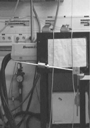
fig.6a: the "gliding pearl" experiment
The stick can rotate around the axis on the support.
In the experiment the stick with the pearl on it is started at the highest point and fall down to the lowest point. During this process the brass body moves outwards.
The experiment is recorded by a video camera. From the video pictures the coordinates of the movement are recorded in aequidistant intervalls of the video frequency (25 Hz). The recording time of the half pictures is set to 1/1000 sec.
24

fig. 6b: "phase plane" angular velocity vs. angle of the gliding pearl experiment the line are theoretical values, markers represent experimental measurements
fig. 6c: "phase plane" radial velocity vs. radius of the gliding pearl experiment the line are theoretical values, markers represent experimental measurements
25

Fig 7a: The Imris experiment Phase 1 Alu frame (slab) and hammer weight (=asymetric rotor) rotate in phase clockwise around the central (black) axis as "rigid" body
Fig.7b: the Imris experiment Phase 2 Alu frame (slab) has bounced against weight( on the left) and is stopped down. The hammer weight (=asymetric rotor) continues to rotate at short radius.of rotation clockwise.
-----------------------------------------------------------------------------
*) anti - © = anti-copyright: text is free and can be copied if authorship and priority dates are acknowledged and if contents is reproduced correctly
26
27