

Phedotikov / 1 / FreeEnergy_27.01.08 / Ядерно-Химические / Experiments Joe cell / PatE16
.pdfA Practical Guide to ‘Free Energy’ Devices
Electrolysis Patents No. 16: Last updated: 30th September 2006 |
Author: Patrick J. Kelly |
The major difficulty in using Stan’s low-current Water Fuel Cell (recently reproduced by Dave Lawton and shown in document “D14.pdf”) is the issue of keeping the cell continuously at the resonant frequency point. This patent application shows the Stan’s circuitry for doing exactly that, and consequently, it is of major importance.
Patent WO 92/07861 |
2nd November 1990 |
Inventor: Stanley A. Meyer |
CONTROL AND DRIVER CIRCUITS FOR A
HYDROGEN GAS FUEL PRODUCING CELL
ABSTRACT
A control circuit for a capacitive resonant cavity water capacitor cell (7) for the production of a hydrogen containing fuel has a resonant scanning circuit co-operating with a resonance detector and PLL circuit to produce pulses. The pulses are fed into the primary transformer (TX1). The secondary transformer (TX2) is connected to the resonant cavity water capacitor cell (7) via a diode and resonant charging chokes (TX4,
TX5).
CONTROL AND DRIVER CIRCUITS FOR A HYDROGEN GAS FUEL PRODUCING CELL
This invention relates to electrical circuit systems useful in the operation of a Water Fuel Cell including a water capacitor/resonant cavity for the production of a hydrogen containing fuel gas, such as that described in my United States Letter Patent No. 4,936,961 “Method for the Production of a Fuel Gas” issued on 26th June 1990.
In my Letters Patent for a “Method for the Production of a Fuel Gas”, voltage pulses applied to the plates of a water capacitor tune into the dielectric properties of the water and attenuate the electrical forces between the hydrogen and oxygen atoms of the molecule. The attenuation of the electrical forces results in a change in the molecular electrical field and the covalent atomic bonding forces of the hydrogen and oxygen atoms. When resonance is achieved, the atomic bond of the molecule is broken, and the atoms of the molecule disassociate. At resonance, the current (amp) draw from a power source to the water capacitor is minimised and voltage across the water capacitor increases. Electron flow is not permitted (except at the minimum, corresponding to leakage resulting from the residual conductive properties of water). For the process to continue, however, a resonant condition must be maintained.
Because of the electrical polarity of the water molecule, the fields produced in the water capacitor respectively attract and repel the opposite and like charges in the molecule, and the forces eventually achieved at resonance are such that the strength of the covalent bonding force in the water molecule (which are normally in an electron-sharing mode) disassociate. Upon disassociation, the formerly shared bonding electrons migrate to the hydrogen nuclei, and both the hydrogen and oxygen revert to net zero electrical charge. The atoms are released from the water as a gas mixture.
In the invention herein, a control circuit for a resonant cavity water capacitor cell utilised for the production of a hydrogen-containing fuel gas is provided.
The circuit includes an isolation means such as a transformer having a ferromagnetic, ceramic or other electromagnetic material core and having one side of a secondary coil connected in series with a high speed switching diode to one plate of the water capacitor of the resonant cavity and the other side of the secondary coil connected to the other plate of the water capacitor to form a closed loop electronic circuit utilising the dielectric properties of water as part of the electronic resonant circuit. The primary coil of the isolation
transformer is connected to a pulse generation means. The secondary coil of the transformer may include segments which form resonant charging choke circuits in series with the water capacitor plates.
In the pulse generation means, an adjustable resonant frequency generator and a gated pulse frequency generator are provided. A gate pulse controls the number of the pulses produced by the resonant frequency generator sent to the primary coil during a period determined by the gate frequency of the second pulse generator.
The invention also includes a means for sensing the occurrence of a resonant condition in the water capacitor / resonant cavity, which when a ferromagnetic or electromagnetic core is used, may be a pickup coil on the transformer core. The sensing means is interconnected to a scanning circuit and a phase lock loop circuit, whereby the pulsing frequency to the primary coil of the transformer is maintained at a sensed frequency corresponding to a resonant condition in the water capacitor.
Control means are provided in the circuit for adjusting the amplitude of a pulsing cycle sent to the primary coil and for maintaining the frequency of the pulsing cycle at a constant frequency regardless of pulse amplitude. In addition, the gated pulse frequency generator may be connected to a sensor which monitors the rate of gas production in the cell and controls the number of pulses from the resonant frequency generator sent to the cell in a gated frequency in correspondence with the rate of gas production. The sensor may be a gas pressure sensor in an enclosed water capacitor resonant cavity which also includes a gas outlet. The gas pressure sensor is connected to the circuit to determine the rate of gas production with respect to ambient gas pressure in the water capacitor enclosure.
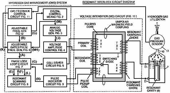
Thus, a comprehensive control circuit and it’s individual components for maintaining and controlling the resonance and other aspects of the release of gas from a resonant cavity water cell is described here and illustrated in the drawings which depict the following:
Fig.1 is a block diagram of an overall control circuit showing the interrelationship of sub-circuits, the pulsing core / resonant circuit and the water capacitor resonant cavity.
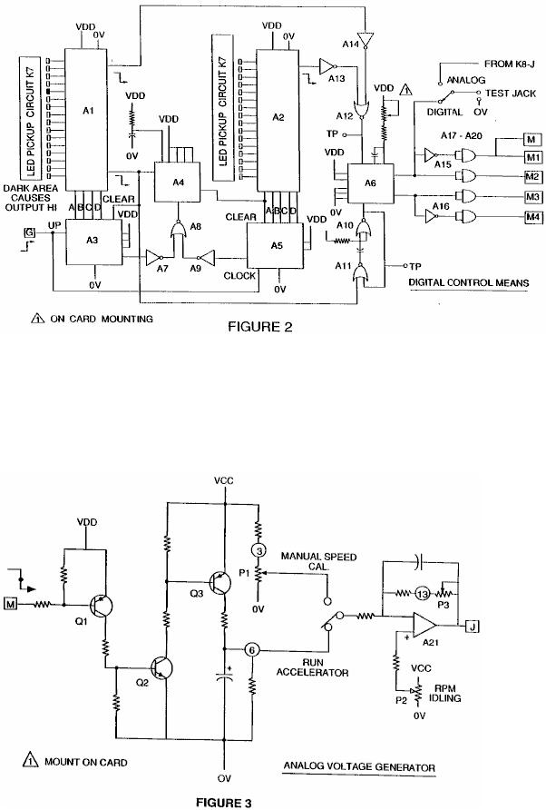
Fig.2 shows a type of digital control circuit for regulating the ultimate rate of gas production as determined by an external input. (Such a control circuit would correspond, for example, to the accelerator in a car, or the thermostat control in a building).
Fig.3 shows an analog voltage generator.
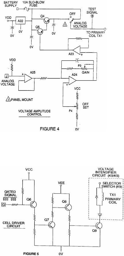
Fig.4 is a voltage amplitude control circuit interconnected with the voltage generator and one side of the primary coil of the pulsing core.
Fig.5 is the cell driver circuit that is connected with the opposite side of the primary coil of the pulsing core. Figures 6 to 9 form the pulsing control circuitry:
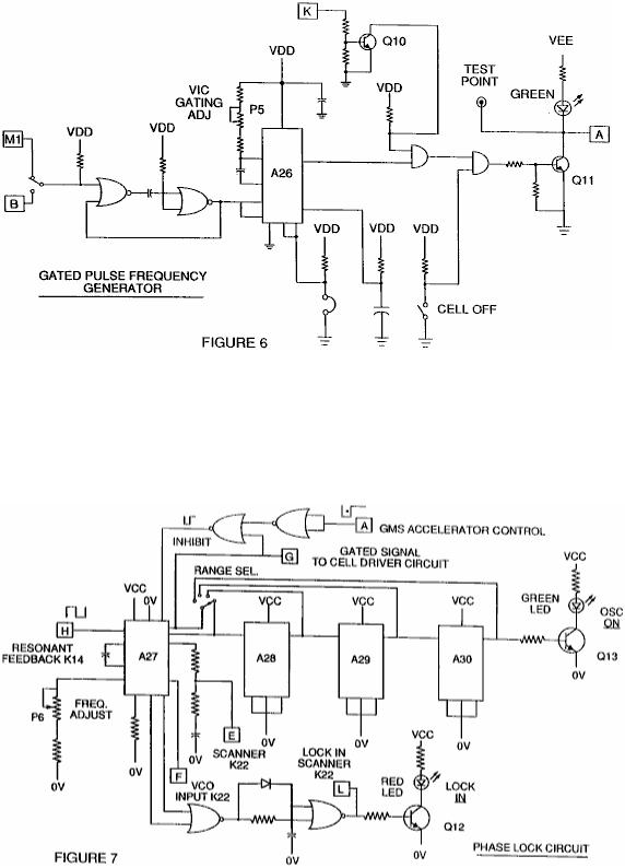
Fig.6 is a gated pulse frequency generator.
Fig.7 is a phase lock circuit.
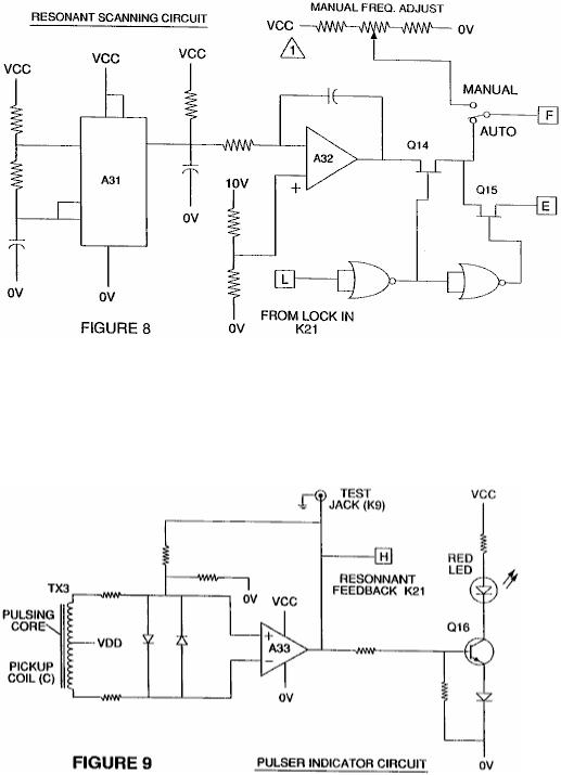
Fig.8 is a resonant scanning circuit
Fig.9 is the pulse indicator circuit.
These four circuits control the pulses transmitted to the resonant-cavity / Water Fuel Cell capacitor.
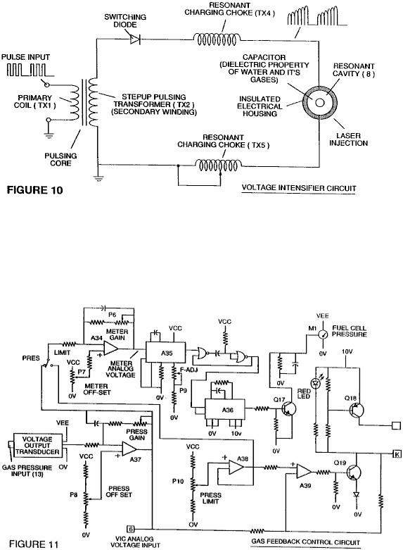
Fig.10 shows the pulsing core and the voltage intensifier circuit which forms the interface between the control circuit and the resonant cavity.
Fig.11 is a gas feedback control circuit
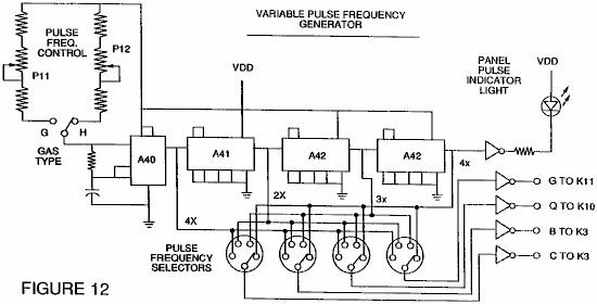
Fig.12 is an adjustable frequency generator circuit.
The circuits are interconnected as shown in Fig.1 and to the pulsing core voltage intensifier circuit of Fig.10, which, among other things, isolates the water capacitor electrically so that it becomes an electrically isolated cavity for the processing of water in accordance with it’s dielectric resonance properties. By reason of this isolation, power consumption in the control and driving circuits is minimised when resonance occurs, and current demand is minimised as voltage is maximised in the gas production mode of the water capacitor / Fuel Cell.
The reference letters “A” through “M” and “M1” show, with respect to each separate circuit shown, the point at which a connection in that circuit is made to another of the circuits shown.
In the invention, the water capacitor is subjected to a duty pulse which builds up in the resonant charging choke coil and then collapses. This occurrence allows a unipolar pulse to be applied to the Fuel Cell capacitor. When a resonant condition of the circuit is locked-in by the circuit, current leakage is held to a minimum as the voltage which creates the dielectric field tends to infinity. Thus, when high voltage is detected upon resonance, the phase-lock-loop circuit, which controls the cell driver circuit, maintains the resonance at the detected (or sensed) frequency.
The resonance of the water capacitor cell is affected by the volume of water in the cell. The resonance of any given volume of water contained in the water capacitor cell is also affected by “contaminants” in the water which act as a damper. For example, with a potential difference of 2,000 to 5,000 volts applied to the cell, a current spike or surge may be caused by inconsistencies in the water characteristics which cause an out-of-resonance condition which is remedied instantaneously by the control circuits.
In the invention, the adjustable frequency generator, shown in Fig.12, tunes in to the resonant condition of the circuit which includes the water cell and the water inside it. The generator has a frequency capability of 0 to 10 KHz and tunes into resonance typically at a frequency of 5 KHz in a typical 3-inch long water capacitor formed from a 0.5 inch rod inside a 0.75 inch inside-diameter cylinder. At start up, in this example, current draw through the water cell will measure about 25 milliamps; however, when the circuit finds a tuned resonant condition, the current drops down to a 1 to 2 milliamp leakage condition.
The voltage to the capacitor water cell increases according to the turns of the winding and the size of the coils, as in a typical transformer circuit. For example, if 12 volts is sent to the primary coil of the pulsing core and the secondary coil resonant charging choke ratio is 30 to 1, then 360 volts is sent to the capacitor water cell. The number of turns is a design variable which controls the voltage of the unipolar pulses sent to the capacitor.
The high-speed switching diode, shown in Fig.10, prevents charge leaking from the charged water in the water capacitor cavity, and the water capacitor as an overall capacitor circuit element, i.e. the pulse and charge status of the water/capacitor never pass through an arbitrary ground. the pulse to the water capacitor is always unipolar. The water capacitor is electrically isolated from the control, input and driver
circuits by the electromagnetic coupling through the core. The switching diode in the Voltage Intensifier Circuit (Fig.10) performs several functions in the pulsing. The diode is an electronic switch which determines the generation and collapse of an electromagnetic field to permit the resonant charging choke(s) to double the applied frequency and it also allows the pulse to be sent to the resonant cavity without discharging the “capacitor” therein. The diode is, of course, selected in accordance with the maximum voltage encountered in the pulsing circuit. A 600 PIV (“Peak Inverse Volts”) fast switching diode, such as an NVR 1550, has been found to be useful in this circuit.
The Voltage Intensifier Circuit of Fig.10 also includes a ferromagnetic or ceramic ferromagnetic pulsing core capable of producing electromagnetic flux lines in response to an electrical pulse input. The flux lines affect both the secondary coil and the resonant charging choke windings equally. Preferably, the core is of a closed loop construction. The effect of the core is to isolate the water capacitor and to prevent the pulsing signal from going below an arbitrary ground and to maintain the charge of the already charged water and water capacitor.
In the pulsing core, the coils are preferably wound in the same direction to maximise the additive effect of the electromagnetic field in them. The magnetic field of the pulsing core is synchronised with the pulse input to the primary coil. The potential from the secondary coil is introduced to the resonant charging choke(s) series circuit elements which are subjected to the same synchronous applied electromagnetic field, simultaneously with the primary pulse.
When resonance occurs, control of the gas output is achieved by varying the time of duty gate cycle. The transformer core is a pulse frequency doubler. In a figurative explanation of the workings of the fuel gas generator water capacitor cell, when a water molecule is “hit” by a pulse, electron time-share is effected and the molecule is charged. When the time of the duty cycle is changed, the number of pulses that “hit” the molecules in the fuel cell is modified correspondingly. More “hits” result in a greater rate of molecular disassociation.
With reference to the overall circuit of Fig.1, Fig.3 receives a digital input signal, and Fig.4 shows the control circuit which applies 0 to 12 volts across the primary coil of the pulsing core. Depending on design parameters of primary coil voltage and other factors relevant to core design, the secondary coil of the pulsing core can be set up for a predetermined maximum, such as 2,000 volts.
The cell driver circuit shown in Fig.5, allows a gated pulse to be varied in direct relation to voltage amplitude. As noted above, the circuit of Fig.6 produces a gate pulse frequency. The gate pulse is superimposed on the resonant frequency pulse, to create a duty cycle that determines the number of discrete pulses sent to the primary coil. For example, assuming a resonant pulse of 5 KHz, a 0.5 KHz gating pulse with a 50% duty cycle, will allow 2,500 discrete pulses to be sent to the primary coil, followed by an equal time interval in which no pulses are passed through. The relationship of resonant pulse to the gate pulse is determined by conventional signal addition/subtraction techniques.
The phase lock loop circuit shown in Fig.7 allows the pulse frequency to be maintained at a predetermined resonant condition sensed by the circuit. Together, the circuits of Fig.7 and Fig.8, determine an output signal to the pulsing core until the peak voltage signal sensed at resonance is achieved.
A resonant condition occurs when the pulse frequency and the voltage input attenuates the covalent bonding forces of the hydrogen and oxygen atoms of the water molecule. When this occurs, current leakage through the water capacitor is minimised. The tendency of voltage to maximise at resonance, increases the force of the electric potential applied to the water molecules, which ultimately disassociate into atoms.
Because resonances of different waters, water volumes and capacitor cells vary, the resonant scanning circuit of Fig.8 scans frequency from high to low and back to high, until a signal lock is achieved. The ferromagnetic core of the voltage intensifier circuit transformer, suppresses electron surge in an out-of- resonance condition of the fuel cell. In an example, the circuit scans at frequencies from 0 Hz to 10 KHz and back to 0 Hz. In water having contaminants in the range of 1 part per million to 20 parts per million, a 20% variation in resonant frequency is encountered. depending on water flow rate into the fuel cell, the normal variation range is about 8% to 10%. For example, iron in well water affects the status of molecular disassociation. Also, at a resonant condition, harmonic effects occur. In a typical operation of the cell with a representative water capacitor described below, at a frequency of about 5 KHz, with unipolar pulses from 0 to 650 volts, at a sensed resonant condition in the resonant cavity, on average, the conversion into gas occurs at a rate of about 5 US gallons (19 litres) of water per hour. To increase the rate, multiple resonant cavities can be used and/or the surfaces of the water capacitor can be increased, however, the water capacitor cell is preferably small in size. A typical water capacitor may be formed from a 0.5 inch diameter
stainless steel rod and a 0.75 inch inside-diameter cylinder which extends over the rod for a length of 3 inches.
The shape and size of the resonant cavity may vary. Larger resonant cavities and higher rates of consumption of water in the conversion process require higher frequencies up to 50 KHz and above. The pulsing rate, to sustain such high rates of conversion, must be increased correspondingly.
From the above description of the preferred embodiment, other variations and modifications of the system disclosed will be evident to those skilled in the art.
CLAIMS
1. A control circuit for a resonant cavity water capacitor cell utilised for the production of a hydrogencontaining fuel gas, including an isolation transformer with a ferromagnetic core, and having one side of a secondary coil connected in series with a high-speed switching diode to one plate of the water capacitor of the resonant cavity, and the other side of the secondary coil connected to the other plate of the water capacitor, to form a closed-loop electronic circuit utilising the dielectric properties of water as part of the electronic circuit, and a primary coil connected to a pulse generator.
2. The circuit of Claim 1. in which the secondary coil includes segments which form a resonant charging choke circuit in series with the water capacitor.
3. The circuit of Claim 1. in which the pulse generator includes an adjustable first frequency generator and a second gated pulse frequency generator which controls the number of pulses produced by the first frequency generator, sent to the primary coil during a period determined by the gate frequency of the second pulse generator.
4. The circuit of Claim 1. further including a means for sensing the occurrence of a resonant condition in the water capacitor of the resonant cavity.
5. The circuit of Claim 4. in which the means for sensing is a pickup coil on the ferromagnetic core of the transformer.
6. The circuit of Claim 4. or Claim 5. in which the sensing means is interconnected to a scanning circuit and a phase-lock-loop circuit, by which the pulsing frequency sent to the primary coil of the transformer is maintained at a sensed frequency corresponding to a resonant condition in the water capacitor.
7. The circuit of Claim 1. including means for adjusting the amplitude of a pulsing cycle sent to the primary coil.
8. The circuit of Claim 6. including further means for maintaining the frequency of the pulsing cycle at a constant frequency regardless of pulse amplitude.
9. the circuit of Claim 3. in which the gated pulse frequency generator is connected to a sensor which monitors the rate of gas production from the cell and controls the number of pulses sent to the cell in a gated frequency, corresponding to the rate of gas production.
10. The circuit of Claim 7. or Claim 8. or Claim 9. further including a gas-pressure sensor in an enclosed water capacitor resonant cavity which also includes a gas outlet, where the gas-pressure sensor is connected to the circuit to determine the rate of gas production with respect to ambient gas pressure in the water capacitor enclosure.
11. The methods and apparatus as substantially described herein.