

- •Textbook Series
- •Contents
- •1 Overview and Definitions
- •Overview
- •General Definitions
- •Glossary
- •List of Symbols
- •Greek Symbols
- •Others
- •Self-assessment Questions
- •Answers
- •2 The Atmosphere
- •Introduction
- •The Physical Properties of Air
- •Static Pressure
- •Temperature
- •Air Density
- •International Standard Atmosphere (ISA)
- •Dynamic Pressure
- •Key Facts
- •Measuring Dynamic Pressure
- •Relationships between Airspeeds
- •Airspeed
- •Errors and Corrections
- •V Speeds
- •Summary
- •Questions
- •Answers
- •3 Basic Aerodynamic Theory
- •The Principle of Continuity
- •Bernoulli’s Theorem
- •Streamlines and the Streamtube
- •Summary
- •Questions
- •Answers
- •4 Subsonic Airflow
- •Aerofoil Terminology
- •Basics about Airflow
- •Two Dimensional Airflow
- •Summary
- •Questions
- •Answers
- •5 Lift
- •Aerodynamic Force Coefficient
- •The Basic Lift Equation
- •Review:
- •The Lift Curve
- •Interpretation of the Lift Curve
- •Density Altitude
- •Aerofoil Section Lift Characteristics
- •Introduction to Drag Characteristics
- •Lift/Drag Ratio
- •Effect of Aircraft Weight on Minimum Flight Speed
- •Condition of the Surface
- •Flight at High Lift Conditions
- •Three Dimensional Airflow
- •Wing Terminology
- •Wing Tip Vortices
- •Wake Turbulence: (Ref: AIC P 072/2010)
- •Ground Effect
- •Conclusion
- •Summary
- •Answers from page 77
- •Answers from page 78
- •Questions
- •Answers
- •6 Drag
- •Introduction
- •Parasite Drag
- •Induced Drag
- •Methods of Reducing Induced Drag
- •Effect of Lift on Parasite Drag
- •Aeroplane Total Drag
- •The Effect of Aircraft Gross Weight on Total Drag
- •The Effect of Altitude on Total Drag
- •The Effect of Configuration on Total Drag
- •Speed Stability
- •Power Required (Introduction)
- •Summary
- •Questions
- •Annex C
- •Answers
- •7 Stalling
- •Introduction
- •Cause of the Stall
- •The Lift Curve
- •Stall Recovery
- •Aircraft Behaviour Close to the Stall
- •Use of Flight Controls Close to the Stall
- •Stall Recognition
- •Stall Speed
- •Stall Warning
- •Artificial Stall Warning Devices
- •Basic Stall Requirements (EASA and FAR)
- •Wing Design Characteristics
- •The Effect of Aerofoil Section
- •The Effect of Wing Planform
- •Key Facts 1
- •Super Stall (Deep Stall)
- •Factors that Affect Stall Speed
- •1g Stall Speed
- •Effect of Weight Change on Stall Speed
- •Composition and Resolution of Forces
- •Using Trigonometry to Resolve Forces
- •Lift Increase in a Level Turn
- •Effect of Load Factor on Stall Speed
- •Effect of High Lift Devices on Stall Speed
- •Effect of CG Position on Stall Speed
- •Effect of Landing Gear on the Stall Speed
- •Effect of Engine Power on Stall Speed
- •Effect of Mach Number (Compressibility) on Stall Speed
- •Effect of Wing Contamination on Stall Speed
- •Warning to the Pilot of Icing-induced Stalls
- •Stabilizer Stall Due to Ice
- •Effect of Heavy Rain on Stall Speed
- •Stall and Recovery Characteristics of Canards
- •Spinning
- •Primary Causes of a Spin
- •Phases of a Spin
- •The Effect of Mass and Balance on Spins
- •Spin Recovery
- •Special Phenomena of Stall
- •High Speed Buffet (Shock Stall)
- •Answers to Questions on Page 173
- •Key Facts 2
- •Questions
- •Key Facts 1 (Completed)
- •Key Facts 2 (Completed)
- •Answers
- •8 High Lift Devices
- •Purpose of High Lift Devices
- •Take-off and Landing Speeds
- •Augmentation
- •Flaps
- •Trailing Edge Flaps
- •Plain Flap
- •Split Flap
- •Slotted and Multiple Slotted Flaps
- •The Fowler Flap
- •Comparison of Trailing Edge Flaps
- •and Stalling Angle
- •Drag
- •Lift / Drag Ratio
- •Pitching Moment
- •Centre of Pressure Movement
- •Change of Downwash
- •Overall Pitch Change
- •Aircraft Attitude with Flaps Lowered
- •Leading Edge High Lift Devices
- •Leading Edge Flaps
- •Effect of Leading Edge Flaps on Lift
- •Leading Edge Slots
- •Leading Edge Slat
- •Automatic Slots
- •Disadvantages of the Slot
- •Drag and Pitching Moment of Leading Edge Devices
- •Trailing Edge Plus Leading Edge Devices
- •Sequence of Operation
- •Asymmetry of High Lift Devices
- •Flap Load Relief System
- •Choice of Flap Setting for Take-off, Climb and Landing
- •Management of High Lift Devices
- •Flap Extension Prior to Landing
- •Questions
- •Annexes
- •Answers
- •9 Airframe Contamination
- •Introduction
- •Types of Contamination
- •Effect of Frost and Ice on the Aircraft
- •Effect on Instruments
- •Effect on Controls
- •Water Contamination
- •Airframe Aging
- •Questions
- •Answers
- •10 Stability and Control
- •Introduction
- •Static Stability
- •Aeroplane Reference Axes
- •Static Longitudinal Stability
- •Neutral Point
- •Static Margin
- •Trim and Controllability
- •Key Facts 1
- •Graphic Presentation of Static Longitudinal Stability
- •Contribution of the Component Surfaces
- •Power-off Stability
- •Effect of CG Position
- •Power Effects
- •High Lift Devices
- •Control Force Stability
- •Manoeuvre Stability
- •Stick Force Per ‘g’
- •Tailoring Control Forces
- •Longitudinal Control
- •Manoeuvring Control Requirement
- •Take-off Control Requirement
- •Landing Control Requirement
- •Dynamic Stability
- •Longitudinal Dynamic Stability
- •Long Period Oscillation (Phugoid)
- •Short Period Oscillation
- •Directional Stability and Control
- •Sideslip Angle
- •Static Directional Stability
- •Contribution of the Aeroplane Components.
- •Lateral Stability and Control
- •Static Lateral Stability
- •Contribution of the Aeroplane Components
- •Lateral Dynamic Effects
- •Spiral Divergence
- •Dutch Roll
- •Pilot Induced Oscillation (PIO)
- •High Mach Numbers
- •Mach Trim
- •Key Facts 2
- •Summary
- •Questions
- •Key Facts 1 (Completed)
- •Key Facts 2 (Completed)
- •Answers
- •11 Controls
- •Introduction
- •Hinge Moments
- •Control Balancing
- •Mass Balance
- •Longitudinal Control
- •Lateral Control
- •Speed Brakes
- •Directional Control
- •Secondary Effects of Controls
- •Trimming
- •Questions
- •Answers
- •12 Flight Mechanics
- •Introduction
- •Straight Horizontal Steady Flight
- •Tailplane and Elevator
- •Balance of Forces
- •Straight Steady Climb
- •Climb Angle
- •Effect of Weight, Altitude and Temperature.
- •Power-on Descent
- •Emergency Descent
- •Glide
- •Rate of Descent in the Glide
- •Turning
- •Flight with Asymmetric Thrust
- •Summary of Minimum Control Speeds
- •Questions
- •Answers
- •13 High Speed Flight
- •Introduction
- •Speed of Sound
- •Mach Number
- •Effect on Mach Number of Climbing at a Constant IAS
- •Variation of TAS with Altitude at a Constant Mach Number
- •Influence of Temperature on Mach Number at a Constant Flight Level and IAS
- •Subdivisions of Aerodynamic Flow
- •Propagation of Pressure Waves
- •Normal Shock Waves
- •Critical Mach Number
- •Pressure Distribution at Transonic Mach Numbers
- •Properties of a Normal Shock Wave
- •Oblique Shock Waves
- •Effects of Shock Wave Formation
- •Buffet
- •Factors Which Affect the Buffet Boundaries
- •The Buffet Margin
- •Use of the Buffet Onset Chart
- •Delaying or Reducing the Effects of Compressibility
- •Aerodynamic Heating
- •Mach Angle
- •Mach Cone
- •Area (Zone) of Influence
- •Bow Wave
- •Expansion Waves
- •Sonic Bang
- •Methods of Improving Control at Transonic Speeds
- •Questions
- •Answers
- •14 Limitations
- •Operating Limit Speeds
- •Loads and Safety Factors
- •Loads on the Structure
- •Load Factor
- •Boundary
- •Design Manoeuvring Speed, V
- •Effect of Altitude on V
- •Effect of Aircraft Weight on V
- •Design Cruising Speed V
- •Design Dive Speed V
- •Negative Load Factors
- •The Negative Stall
- •Manoeuvre Boundaries
- •Operational Speed Limits
- •Gust Loads
- •Effect of a Vertical Gust on the Load Factor
- •Effect of the Gust on Stalling
- •Operational Rough-air Speed (V
- •Landing Gear Speed Limitations
- •Flap Speed Limit
- •Aeroelasticity (Aeroelastic Coupling)
- •Flutter
- •Control Surface Flutter
- •Aileron Reversal
- •Questions
- •Answers
- •15 Windshear
- •Introduction (Ref: AIC 84/2008)
- •Microburst
- •Windshear Encounter during Approach
- •Effects of Windshear
- •“Typical” Recovery from Windshear
- •Windshear Reporting
- •Visual Clues
- •Conclusions
- •Questions
- •Answers
- •16 Propellers
- •Introduction
- •Definitions
- •Aerodynamic Forces on the Propeller
- •Thrust
- •Centrifugal Twisting Moment (CTM)
- •Propeller Efficiency
- •Variable Pitch Propellers
- •Power Absorption
- •Moments and Forces Generated by a Propeller
- •Effect of Atmospheric Conditions
- •Questions
- •Answers
- •17 Revision Questions
- •Questions
- •Answers
- •Explanations to Specimen Questions
- •Specimen Examination Paper
- •Answers to Specimen Exam Paper
- •Explanations to Specimen Exam Paper
- •18 Index

13 High Speed Flight
The Buffet Margin
Flight Speed High 13
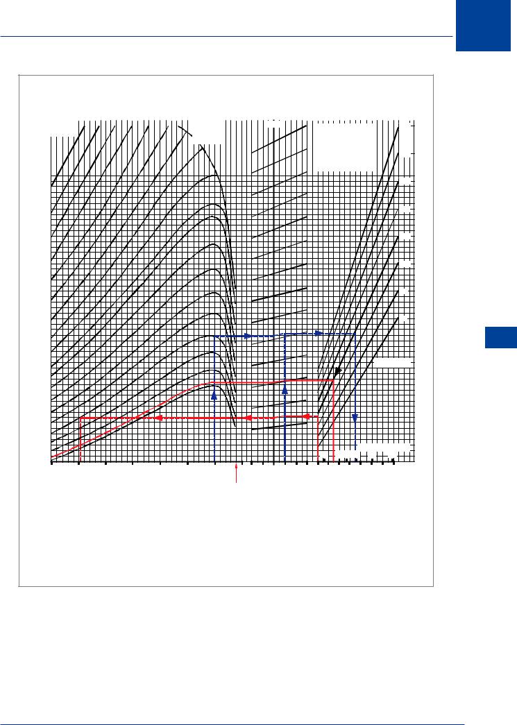
It has been stated that an altitude can eventually be reached where there is only one speed at which the aircraft can fly. In the case of a 1g manoeuvre, this altitude is called the ‘Aerodynamic Ceiling’. Operating an aircraft at its aerodynamic ceiling would leave no safety margin. In 1g flight the aircraft would be constantly on the point of stall. It could not be manoeuvred nor experience the smallest gust without stalling. Regulations require an aircraft to be operated with a minimum buffet margin of 0.3g.
Use of the Buffet Onset Chart
(Figure 13.26)
1.3g Altitude (1g + 0.3g = 1.3g): At this altitude a ‘g’ increment of 0.3 can be sustained without buffet occurring. Using the data supplied:
Follow the vertical solid red line upwards from 1.3g to the 110 tonnes line, then horizontally to the 30% CG vertical line, then parallel to the CG reference line, again horizontally to the M 0.8 vertical line. The altitude curve must now be ‘paralleled’ to read-off the Flight Level of 405. The 1.3g altitude is 40 500 ft.
If the aircraft is operated above FL405 at this mass and CG, a gust, or bank angle of less than 40°, could cause the aircraft to buffet. (40° of bank at high altitude is excessive, a normal operational maximum at high altitude would be 10° to 15°).
Buffet restricted speed limits: Using the data supplied:
Follow the vertical dashed red line upwards from 1g to the 110 tonnes line, then horizontally to the 30% CG vertical line, then parallel to the CG reference line. Observe the FL350 curve. The curve does not reach the horizontal dashed red line at the high speed end because M 0.84 (MMO) is the maximum operating speed limit. At the low speed end of the dashed red line, the FL350 curve is intersected at M 0.555. Thus under the stated conditions, the low speed buffet restriction is M 0.555 and there is no high speed buffet restriction because MMO is the maximum operating Mach number which may not be exceeded under any circumstances.
Aerodynamic ceiling: at 150 tonnes can be determined by:
Initially following the red dashed line vertically upwards from 1g, continue to the 150 tonnes plot, then move horizontally to the left to M0.8 (via the CG correction). The interpolated altitude curve gives an aerodynamic ceiling of FL390.
Load factor and bank angle at which buffet occurs: Using the data supplied:
From M 0.8, follow the dashed blue line to obtain 54° bank angle or 1.7g.
432
High Speed Flight 13
BUFFET ONSET clean configuration
|
|
|
|
|
|
|
|
|
|
|
|
|
|
|
REF |
|
|
|
|
|
|
|
|
|
|
|
|
|
|
|
|
|
|
|
|
|
|
|
|
NOTE: |
|
150 |
|
||
FLIGHT LEVEL |
|
|
|
|
|
|
|
|
|
|
|
|||||||||||
|
|
|
|
|
|
|
|
|
|
|
FOR MACH NUMBERS |
|
|
|
|
|
||||||
|
|
|
|
|
|
|
VMO LIMIT |
|
|
|
|
|
|
|
|
|||||||
|
|
|
|
|
|
|
|
|
|
|
|
|
|
|
||||||||
|
|
|
|
|
|
|
|
|
|
ABOVE OR EQUAL TO |
|
|
|
|
|
|||||||
|
|
|
|
|
|
|
|
|
|
|
|
|
|
|
||||||||
|
|
|
|
|
|
|
|
|
|
|
|
|
|
|
|
|
.82 THERE IS NO C.G. |
|
|
|
|
|
|
|
|
|
|
|
|
|
|
|
|
|
|
|
|
|
|
VARIATION EFFECT |
|
|
140 |
|
|
|
|
|
|
|
|
|
|
|
|
|
|
|
|
|
|
|
|
|||||
|
|
|
|
|
|
|
|
|
|
|
|
|
|
|
|
|
FROM REFERENCE |
|
|
|
|
|
|
|
|
|
|
|
|
|
|
|
|
|
|
|
|
|
|
|
|
|
|
|
|
|
|
|
|
|
|
|
|
|
|
|
|
|
|
|
|
|
VALUE |
|
|
|
|
|
|
|
|
|
|
|
|
|
|
|
|
|
|
|
|
|
|
|
|
|
|
|
|
60 |
|
|
|
|
|
|
|
|
|
|
|
|
130 |
|
|
|
|
|
|
|
|
|
|
|
|
|
|
80 |
|
|
|
|
|
|
|
|
|
|
|
|
120 |
|
|
|
|
|
|
|
|
|
|
|
|
|
|
100 |
|
|
|
|
|
|
|
|
|
|
|
|
110 |
120 |
|
|
|
|
|
|
|
|
|
|
|
|
100 |
140 |
|
|
|
|
|
|
|
|
|
|
|
|
|
|
|
|
|
|
|
|
|
|
|
|
|
|
90 |
160 |
|
|
|
|
|
|
|
|
|
|
|
|
|
180 |
|
|
|
|
|
|
|
|
|
|
|
|
80 |
|
|
|
|
|
|
|
|
|
|
|
|
|
|
200 |
|
|
|
|
|
|
|
|
|
|
|
|
|
220 |
|
|
|
|
|
|
|
|
|
|
|
|
|
240 |
|
|
|
|
|
|
|
|
|
|
W EIGHT |
( t ) |
|
|
|
|
|
|
|
|
|
|
|
|
|
|
|
250 |
|
|
|
|
|
|
|
|
|
|
|
|
|
270 |
|
|
|
|
|
|
|
|
|
|
|
|
|
290 |
|
|
|
|
|
|
|
|
|
|
|
|
|
310 |
|
|
|
|
|
|
|
|
|
|
|
|
|
330 |
|
|
|
|
|
|
|
|
|
|
|
|
|
350 |
|
|
|
|
|
|
|
|
|
|
|
|
|
370 |
|
|
|
|
|
|
|
|
|
BANK ANGLE ( o) |
|||
390 |
|
|
|
|
|
|
|
|
|
||||
|
|
|
|
|
|
|
|
30 |
45 50 55 |
60 |
65 |
|
|
410 |
|
|
|
|
|
|
|
|
|
||||
|
|
|
|
|
|
|
|
|
|
|
|
|
|
.50 |
.55 |
.60 |
.65 |
.70 |
.75 |
.80 |
.85 15 20 25 30 35 40 |
1 |
1.2 |
1.4 1.6 1.8 |
2 |
2.2 2.4 |
|
|
|
|
MACH NUMBER |
|
|
CG% |
|
|
LOAD FACTOR |
|
|
||
|
|
|
|
|
|
|
MMO |
|
|
|
|
|
|
DATA : M = .80 |
RESULTS : BUFFET ONSET AT : |
|
|
FL = 350 |
M = 0.80 WITH 54O BANK ANGLE, OR AT 1.7g |
WEIGHT = 110 tonnes |
LOW SPEED (1g) : M = 0.555 |
CG = 30 % |
HIGH SPEED : ABOVE M 0.84 ( MMO) |
|
1.3g ALTITUDE = FL405 |
Figure 13.26 Example of a buffet onset chart
High Speed Flight 13
433

13 High Speed Flight
Delaying or Reducing the Effects of Compressibility
Flight Speed High 13
To maximize revenue, airlines require their aircraft to fly as fast and as efficiently as possible. It has been shown that the formation of shock waves on the wing results in many undesirable characteristics and a massive increase in drag. Up to speeds in the region of MCRIT the effects of compressibility are not too serious. It is therefore necessary to increase MCRIT as much as possible. Many methods have been adopted to delay or reduce the effects of compressibility to a higher Mach number, as detailed below.
ThinWing Sections
On a low t/c ratio wing, the flow acceleration is reduced, thus raising the value of MCRIT. For example if MCRIT for a 15% t/c wing is M 0.75, then MCRIT for a 5% t/c wing will be approximately M 0.85.
The use of a low t/c ratio wing section has some disadvantages:
•The lift produced by a thin wing will be less, giving higher take-off and landing speeds and increased distances.
•A thin wing requires disproportionally wider main spars for the same strength and stiffness. This increases structural weight.
•Limited stowage space is available in a thin wing for:
•fuel
•high lift devices and their actuating mechanism and
•the main undercarriage and its actuating mechanism.
Sweepback (see Page 449 for Sweepback Fact Sheet)
One of the most commonly used methods of increasing MCRIT is to sweep the wing back. Forward sweep gives a similar effect but wing bending and twisting creates such a problem
that sweepback is more practical for ordinary applications.
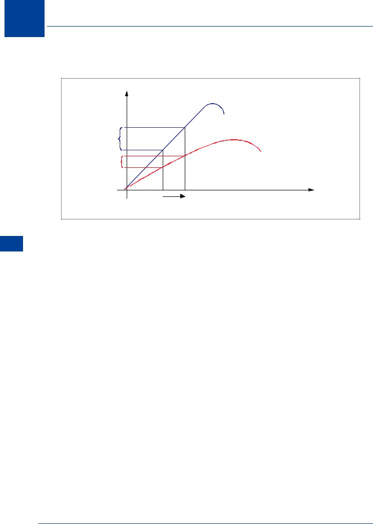
A simplified method of visualizing the effect of sweepback is shown in Figure 13.27. The swept wing shown has the free stream velocity broken down to a component of velocity perpendicular to the leading edge and a component parallel to the leading edge.
The component of velocity perpendicular to the leading edge is less than the free stream velocity (by the cosine of the sweep angle) and it is this velocity component which determines the magnitude of the pressure distribution. MCRIT will increase since the velocity component affecting the pressure distribution is less than the free stream velocity.
434
High Speed Flight 13
VELOCITY COMPONENT
PARALLEL TO LEADING
EDGE
FREE STREAM
VELOCITY
SWEEP ANGLE
VELOCITY COMPONENT PERPENDICULAR TO LEADING EDGE
Figure 13.27 Effect of sweepback
SAME |
CHORD |
FREE |
STREAM |
FLOW |
SAME |
CHORD |
EFFECTIVE |
AERODYNAMIC |
CHORD |
INCREASED |
Figure 13.28
Alternatively, it can be considered that compared to a straight wing, a swept-back wing of the same aerofoil section has a smaller effective thickness chord ratio. Sweeping the wing back increases the effective aerodynamic chord for the same dimensional thickness,
Figure 13.28.
The local velocity will be lower for a given
free stream velocity. In this way, the MCRIT of a swept wing will be higher than that of a
straight wing.
Sweeping the wing back has nearly the same aerodynamic advantages as a thin wing, without suffering reduced strength and fuel capacity. Unfortunately, there are some disadvantages. It was explained in Chapter 7 that swept-back wings tend to tip stall, leading to pitch-up and possibly super stall. Sweptback wings also increase the magnitude of high speed tuck.
High Speed Flight 13
435
13 High Speed Flight
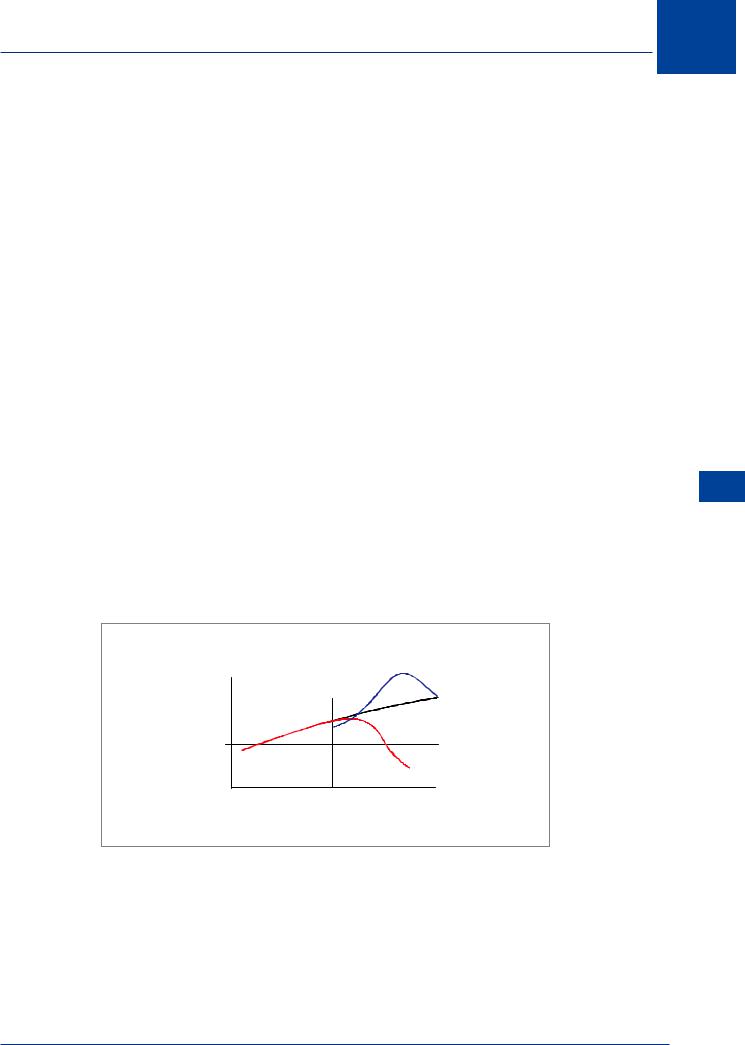
Another advantage of sweepback is the reduced lift curve slope. This is illustrated by the lift curve comparison in Figure 13.29 for the straight and swept wing.
Flight Speed High 13
CL |
STRAIGHT |
SWEPT
ANGLE OF ATTACK
Figure 13.29 Effect of sweepback on sensitivity to gusts
Any reduction of lift curve slope makes the wing less sensitive to changes in angle of attack due to a gust or turbulence. Since the swept wing has the lower lift curve slope, a given vertical gust will increase the CL, and hence the load factor, by a smaller amount than would occur if the wing were straight.
Disadvantages of Sweep
•Reduced CLMAX
•gives a higher stall speed and increased take-off and landing distances.
•Maximum lift angle of attack is increased, which complicates the problem of landing gear design (possibility of tail-strike) and reduced visibility from the flight deck during takeoff and landing. The contribution to stability of a given tail surface area is also reduced.
•A swept-back wing has an increased tendency to tip stall resulting in pitch-up at the stall and possible deep stall problems.
•Reduced effectiveness of trailing edge control surfaces and high lift devices because their
hinge line is swept. To produce a reasonable CLMAX on a swept wing the hinge line of the inboard flaps may be made straight. Leading edge high lift devices are also used to improve the low speed characteristics.
436
High Speed Flight 13
Vortex Generators
It has been shown that most of the unfavourable characteristics associated with compressibility are due to boundary layer separation behind the shock wave (shock stall).
Flow separation occurs because the boundary layer loses kinetic energy as it flows against the adverse pressure gradient. Shock wave formation increases the adverse pressure gradient so the loss of kinetic energy in the boundary layer will be greater.
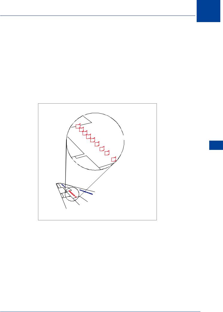
Increasing the kinetic energy of the boundary layer will reduce flow separation. Simple devices called vortex generators are used to re-energize the boundary layer.
Vortex generators are small plates, vanes, blades or wedges mounted in spanwise rows along the wing surface, as illustrated in Figure 13.30.
VORTEX GENERATORS
High Speed Flight 13
Figure 13.30 Vortex generators (blade type)
Each vortex generator produces a vortex at its tip which will induce high energy air from the free stream flow to mix with the boundary layer, thus increasing its kinetic energy and helping it flow through the shock wave with much less separation.
Vortex generators are usually located on the upper wing surface, particularly ahead of control surfaces, but may be used anywhere where separation is causing high drag or reduced control effectiveness. It should be noted that vortex generators may also be used on subsonic aircraft to prevent separation caused by high adverse pressure gradients due to the contours of the surface.
437
13
Flight Speed High 13
High Speed Flight
Area Rule
In Chapter 6 it was stated that in addition to the drag of individual components there is an extra drag due to interference between these components, principally between wing and fuselage. This is especially important at high speed. Experiments have shown that a large part of the transonic drag rise for a complete aircraft is due to interference. Interference drag at transonic speeds may be minimized by ensuring that the cross-sectional area distribution along the aircraft’s longitudinal axis follows a certain smooth pattern.
|
WING |
|
TAIL |
|
FUSELAGE |
NOSE |
TAIL |
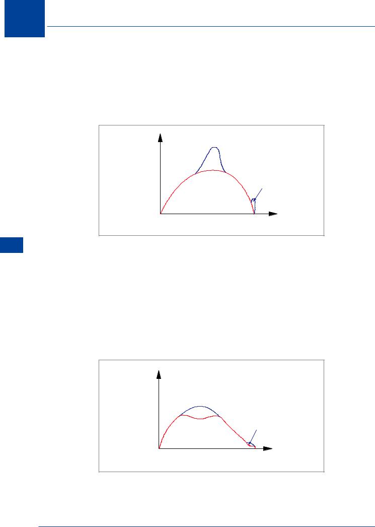
Figure 13.31 Without area rule
With some early high speed aircraft designs this was not the case. The area increased rapidly in the region of the wing, again in the vicinity of the tail and decreased elsewhere, giving an area distribution like the one illustrated in Figure 13.31.
On later aircraft, the fuselage was waisted, i.e. the area was reduced in the region of the wing attachment, and again near the tail, so that there was no “hump” in the area distribution, giving a distribution like the one illustrated in Figure 13.32. There is an optimum area distribution, and the minimization of transonic interference drag requires that the aircraft should be designed to fit this distribution as closely as possible. This requirement is known as the ‘transonic area rule’. In practice, no aircraft has this optimum distribution, but any reasonably smooth area distribution helps to reduce the transonic drag rise.
|
WING |
|
TAIL |
|
FUSELAGE |
NOSE |
TAIL |
Figure 13.32 Area rule
438
High Speed Flight
MachTrim
It was stated on page 423 to page 426 that as speed increases beyond MCRIT, shock wave formation at the root of a swept-back wing will generate a nose-down pitching moment
because lift forward of the CG is reduced and downwash at the tailplane is reduced.
At high Mach numbers an aircraft will tend to become speed unstable. Instead of an increasing push force being required as speed increases, a pull force becomes necessary to prevent the aircraft accelerating further. This is potentially very dangerous. A small increase in Mach number will give a nose-down pitching moment which will tend to further increase the Mach number. This in turn leads to a further increase in the nose-down pitching moment. This unfavourable high speed characteristic, known as “Mach Tuck”, ”High Speed Tuck” or “Tuck Under” would restrict the maximum operating speed of a modern high speed jet transport aircraft.
Some improvement can be made by mounting the tailplane on top of the fin, where it is clear of the downwash, but it has been shown that this can produce a deep stall problem.
To maintain the required stick force gradient at high Mach numbers, a Mach trim system must be fitted. This device, sensitive to Mach number, may:
•deflect the elevator up.
•decrease the incidence of the variable incidence trimming tailplane.
•move the CG rearwards by transferring fuel from the wings to a rear trim tank.
by an amount greater than that required merely to compensate for the trim change. This ensures the required stick force gradient is maintained in the cruise at high Mach numbers.
Whichever method of trim is used by a particular manufacturer, a Mach trim system will adjust longitudinal trim and operates only at high Mach numbers.
|
PUSH |
MACH TRIM |
|
INPUT |
|
|
|
|
|
|
RESULTANT STICK |
STICK |
|
FORCE |
FORCE |
0 |
|
|
BASIC STICK |
|
|
|
|
|
|
FORCE |
|
PULL |
|
MCRIT MACH NUMBER
Figure 13.33 Effect of Mach trim
13
High Speed Flight 13
439
13 High Speed Flight
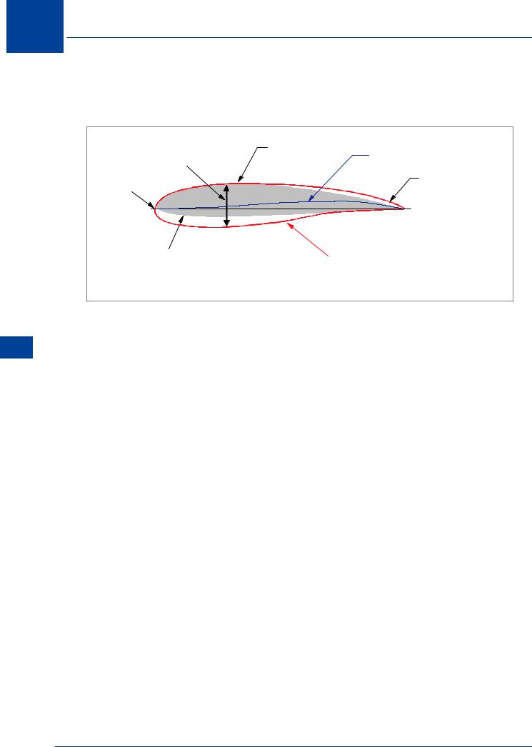
Supercritical Aerofoil
A fairly recent design development, used to increase efficiency when operating in the transonic speed region, is the ‘supercritical aerofoil’.
Flight Speed High 13
LARGE |
FLAT UPPER |
S - SHAPED CAMBER LINE |
SURFACE |
||
THICKNESS |
|
|
BLUNT |
|
THICK TRAILING |
|
EDGE |
|
NOSE |
|
|
|
|
12% |
17% |
|
CONVENTIONAL |
||
SUPERCRITICAL |
||
SECTION |
||
SECTION |
||
|
Figure 13.34 Supercritical aerofoil shape
A supercritical aerofoil shape, illustrated in Figure 13.34, differs from a conventional section by having:
•a blunt nose.
•large thickness.
•an S - shaped camber line.
•a relatively flat upper surface.
•a thick trailing edge.
Because the airflow does not achieve the same increase of speed over the flattened upper surface compared to a conventional section, the formation of shock waves is delayed to a higher MFS and, the shock waves are much smaller and weaker when they do form.
Because the shock waves are smaller and weaker, there is not such a sharp pressure rise on the rear of the section and this gives a much more even ‘loading’ on the wing.
440

High Speed Flight
The Advantages of a Supercritical Aerofoil
•Because of the delayed formation of shock waves and their weaker nature, less sweep angle is required for a given cruising Mach number, thus reducing some of the problems associated with sweepback.
•The greater thickness gives increased stiffness and strength for a given structural weight. This also allows a higher aspect ratio to be used which reduces induced drag.
•The increased section depth gives more storage space for fuel.
This type of wing section can be used to increase performance in one of two ways:
•Increased Payload
By using existing cruise speeds, the fuel consumption would be reduced, thus allowing an increase in payload with little or no drag increase over a conventional wing at the same speed.
•Increased Cruising Speed
By retaining existing payloads, the cruise Mach number could be increased with little or no increase in drag.
The Disadvantages of a Supercritical Aerofoil
•The aerofoil front section has a negative camber to give optimum performance at cruise
Mach numbers, but this is less than ideal for low speed flight. CLMAX will be reduced, requiring extensive and complex high lift devices at the leading edge, which may include Krueger flaps, variable camber flaps, slats and slots.
•The trailing edge of the aerofoil has large positive camber to produce the ‘aft loading’ required, but which also gives large negative (nose-down) pitching moments.
•This must be balanced by the tailplane, causing trim drag.
•Shock induced buffet may cause severe oscillations.
13
High Speed Flight 13
441