

- •Textbook Series
- •Contents
- •1 Overview and Definitions
- •Overview
- •General Definitions
- •Glossary
- •List of Symbols
- •Greek Symbols
- •Others
- •Self-assessment Questions
- •Answers
- •2 The Atmosphere
- •Introduction
- •The Physical Properties of Air
- •Static Pressure
- •Temperature
- •Air Density
- •International Standard Atmosphere (ISA)
- •Dynamic Pressure
- •Key Facts
- •Measuring Dynamic Pressure
- •Relationships between Airspeeds
- •Airspeed
- •Errors and Corrections
- •V Speeds
- •Summary
- •Questions
- •Answers
- •3 Basic Aerodynamic Theory
- •The Principle of Continuity
- •Bernoulli’s Theorem
- •Streamlines and the Streamtube
- •Summary
- •Questions
- •Answers
- •4 Subsonic Airflow
- •Aerofoil Terminology
- •Basics about Airflow
- •Two Dimensional Airflow
- •Summary
- •Questions
- •Answers
- •5 Lift
- •Aerodynamic Force Coefficient
- •The Basic Lift Equation
- •Review:
- •The Lift Curve
- •Interpretation of the Lift Curve
- •Density Altitude
- •Aerofoil Section Lift Characteristics
- •Introduction to Drag Characteristics
- •Lift/Drag Ratio
- •Effect of Aircraft Weight on Minimum Flight Speed
- •Condition of the Surface
- •Flight at High Lift Conditions
- •Three Dimensional Airflow
- •Wing Terminology
- •Wing Tip Vortices
- •Wake Turbulence: (Ref: AIC P 072/2010)
- •Ground Effect
- •Conclusion
- •Summary
- •Answers from page 77
- •Answers from page 78
- •Questions
- •Answers
- •6 Drag
- •Introduction
- •Parasite Drag
- •Induced Drag
- •Methods of Reducing Induced Drag
- •Effect of Lift on Parasite Drag
- •Aeroplane Total Drag
- •The Effect of Aircraft Gross Weight on Total Drag
- •The Effect of Altitude on Total Drag
- •The Effect of Configuration on Total Drag
- •Speed Stability
- •Power Required (Introduction)
- •Summary
- •Questions
- •Annex C
- •Answers
- •7 Stalling
- •Introduction
- •Cause of the Stall
- •The Lift Curve
- •Stall Recovery
- •Aircraft Behaviour Close to the Stall
- •Use of Flight Controls Close to the Stall
- •Stall Recognition
- •Stall Speed
- •Stall Warning
- •Artificial Stall Warning Devices
- •Basic Stall Requirements (EASA and FAR)
- •Wing Design Characteristics
- •The Effect of Aerofoil Section
- •The Effect of Wing Planform
- •Key Facts 1
- •Super Stall (Deep Stall)
- •Factors that Affect Stall Speed
- •1g Stall Speed
- •Effect of Weight Change on Stall Speed
- •Composition and Resolution of Forces
- •Using Trigonometry to Resolve Forces
- •Lift Increase in a Level Turn
- •Effect of Load Factor on Stall Speed
- •Effect of High Lift Devices on Stall Speed
- •Effect of CG Position on Stall Speed
- •Effect of Landing Gear on the Stall Speed
- •Effect of Engine Power on Stall Speed
- •Effect of Mach Number (Compressibility) on Stall Speed
- •Effect of Wing Contamination on Stall Speed
- •Warning to the Pilot of Icing-induced Stalls
- •Stabilizer Stall Due to Ice
- •Effect of Heavy Rain on Stall Speed
- •Stall and Recovery Characteristics of Canards
- •Spinning
- •Primary Causes of a Spin
- •Phases of a Spin
- •The Effect of Mass and Balance on Spins
- •Spin Recovery
- •Special Phenomena of Stall
- •High Speed Buffet (Shock Stall)
- •Answers to Questions on Page 173
- •Key Facts 2
- •Questions
- •Key Facts 1 (Completed)
- •Key Facts 2 (Completed)
- •Answers
- •8 High Lift Devices
- •Purpose of High Lift Devices
- •Take-off and Landing Speeds
- •Augmentation
- •Flaps
- •Trailing Edge Flaps
- •Plain Flap
- •Split Flap
- •Slotted and Multiple Slotted Flaps
- •The Fowler Flap
- •Comparison of Trailing Edge Flaps
- •and Stalling Angle
- •Drag
- •Lift / Drag Ratio
- •Pitching Moment
- •Centre of Pressure Movement
- •Change of Downwash
- •Overall Pitch Change
- •Aircraft Attitude with Flaps Lowered
- •Leading Edge High Lift Devices
- •Leading Edge Flaps
- •Effect of Leading Edge Flaps on Lift
- •Leading Edge Slots
- •Leading Edge Slat
- •Automatic Slots
- •Disadvantages of the Slot
- •Drag and Pitching Moment of Leading Edge Devices
- •Trailing Edge Plus Leading Edge Devices
- •Sequence of Operation
- •Asymmetry of High Lift Devices
- •Flap Load Relief System
- •Choice of Flap Setting for Take-off, Climb and Landing
- •Management of High Lift Devices
- •Flap Extension Prior to Landing
- •Questions
- •Annexes
- •Answers
- •9 Airframe Contamination
- •Introduction
- •Types of Contamination
- •Effect of Frost and Ice on the Aircraft
- •Effect on Instruments
- •Effect on Controls
- •Water Contamination
- •Airframe Aging
- •Questions
- •Answers
- •10 Stability and Control
- •Introduction
- •Static Stability
- •Aeroplane Reference Axes
- •Static Longitudinal Stability
- •Neutral Point
- •Static Margin
- •Trim and Controllability
- •Key Facts 1
- •Graphic Presentation of Static Longitudinal Stability
- •Contribution of the Component Surfaces
- •Power-off Stability
- •Effect of CG Position
- •Power Effects
- •High Lift Devices
- •Control Force Stability
- •Manoeuvre Stability
- •Stick Force Per ‘g’
- •Tailoring Control Forces
- •Longitudinal Control
- •Manoeuvring Control Requirement
- •Take-off Control Requirement
- •Landing Control Requirement
- •Dynamic Stability
- •Longitudinal Dynamic Stability
- •Long Period Oscillation (Phugoid)
- •Short Period Oscillation
- •Directional Stability and Control
- •Sideslip Angle
- •Static Directional Stability
- •Contribution of the Aeroplane Components.
- •Lateral Stability and Control
- •Static Lateral Stability
- •Contribution of the Aeroplane Components
- •Lateral Dynamic Effects
- •Spiral Divergence
- •Dutch Roll
- •Pilot Induced Oscillation (PIO)
- •High Mach Numbers
- •Mach Trim
- •Key Facts 2
- •Summary
- •Questions
- •Key Facts 1 (Completed)
- •Key Facts 2 (Completed)
- •Answers
- •11 Controls
- •Introduction
- •Hinge Moments
- •Control Balancing
- •Mass Balance
- •Longitudinal Control
- •Lateral Control
- •Speed Brakes
- •Directional Control
- •Secondary Effects of Controls
- •Trimming
- •Questions
- •Answers
- •12 Flight Mechanics
- •Introduction
- •Straight Horizontal Steady Flight
- •Tailplane and Elevator
- •Balance of Forces
- •Straight Steady Climb
- •Climb Angle
- •Effect of Weight, Altitude and Temperature.
- •Power-on Descent
- •Emergency Descent
- •Glide
- •Rate of Descent in the Glide
- •Turning
- •Flight with Asymmetric Thrust
- •Summary of Minimum Control Speeds
- •Questions
- •Answers
- •13 High Speed Flight
- •Introduction
- •Speed of Sound
- •Mach Number
- •Effect on Mach Number of Climbing at a Constant IAS
- •Variation of TAS with Altitude at a Constant Mach Number
- •Influence of Temperature on Mach Number at a Constant Flight Level and IAS
- •Subdivisions of Aerodynamic Flow
- •Propagation of Pressure Waves
- •Normal Shock Waves
- •Critical Mach Number
- •Pressure Distribution at Transonic Mach Numbers
- •Properties of a Normal Shock Wave
- •Oblique Shock Waves
- •Effects of Shock Wave Formation
- •Buffet
- •Factors Which Affect the Buffet Boundaries
- •The Buffet Margin
- •Use of the Buffet Onset Chart
- •Delaying or Reducing the Effects of Compressibility
- •Aerodynamic Heating
- •Mach Angle
- •Mach Cone
- •Area (Zone) of Influence
- •Bow Wave
- •Expansion Waves
- •Sonic Bang
- •Methods of Improving Control at Transonic Speeds
- •Questions
- •Answers
- •14 Limitations
- •Operating Limit Speeds
- •Loads and Safety Factors
- •Loads on the Structure
- •Load Factor
- •Boundary
- •Design Manoeuvring Speed, V
- •Effect of Altitude on V
- •Effect of Aircraft Weight on V
- •Design Cruising Speed V
- •Design Dive Speed V
- •Negative Load Factors
- •The Negative Stall
- •Manoeuvre Boundaries
- •Operational Speed Limits
- •Gust Loads
- •Effect of a Vertical Gust on the Load Factor
- •Effect of the Gust on Stalling
- •Operational Rough-air Speed (V
- •Landing Gear Speed Limitations
- •Flap Speed Limit
- •Aeroelasticity (Aeroelastic Coupling)
- •Flutter
- •Control Surface Flutter
- •Aileron Reversal
- •Questions
- •Answers
- •15 Windshear
- •Introduction (Ref: AIC 84/2008)
- •Microburst
- •Windshear Encounter during Approach
- •Effects of Windshear
- •“Typical” Recovery from Windshear
- •Windshear Reporting
- •Visual Clues
- •Conclusions
- •Questions
- •Answers
- •16 Propellers
- •Introduction
- •Definitions
- •Aerodynamic Forces on the Propeller
- •Thrust
- •Centrifugal Twisting Moment (CTM)
- •Propeller Efficiency
- •Variable Pitch Propellers
- •Power Absorption
- •Moments and Forces Generated by a Propeller
- •Effect of Atmospheric Conditions
- •Questions
- •Answers
- •17 Revision Questions
- •Questions
- •Answers
- •Explanations to Specimen Questions
- •Specimen Examination Paper
- •Answers to Specimen Exam Paper
- •Explanations to Specimen Exam Paper
- •18 Index

High Speed Flight
Control Buzz
If a shock wave is situated near to a control hinge, a control movement may cause the shock wave to move over the hinge, resulting in rapid changes of hinge moment which can set up an oscillation of the control surface called control buzz.
Buffet
In the same way that separated airflow prior to a low speed stall can cause airframe buffet, shock induced separation (shock stall) at high speed can also cause buffeting.
Aerodynamic buffet is a valuable stall warning, but it can damage the aircraft structure. Because of the higher dynamic pressure when an aircraft is operating in the transonic speed region, any shock induced buffet will have a greater potential for severe airframe damage. High speed buffet must be completely avoided.
The aircraft must therefore be operated in such a manner that a (safety) margin exists before aerodynamic buffet will occur.
If the variables which affect both high speed and low speed stall are considered it will be possible to identify the conditions under which buffeting will occur and a chart can be drawn to show all the factors involved. This is called a ‘Buffet Onset’ chart (illustrated in Figure 13.26) which is used by flight crews to ensure their aircraft is operated at all times with a specified minimum buffet margin.
In Chapter 7 it was shown that stall speed is affected by several factors. In this study of low speed stall combined with high speed buffet, the factors to be considered are:
•Load factor (bank angle).
•Mach number.
•Angle of attack.
•Pressure altitude.
•Weight.
•CG position.
13
High Speed Flight 13
427
13
Flight Speed High 13
High Speed Flight
Factors Which Affect the Buffet Boundaries
Stall Speed
As altitude is increased at a constant EAS, TAS will increase and outside air temperature will decrease, causing the local speed of sound to decrease. Mach number is proportional to TAS and inversely proportional to the local speed of sound (a):
TAS M = a
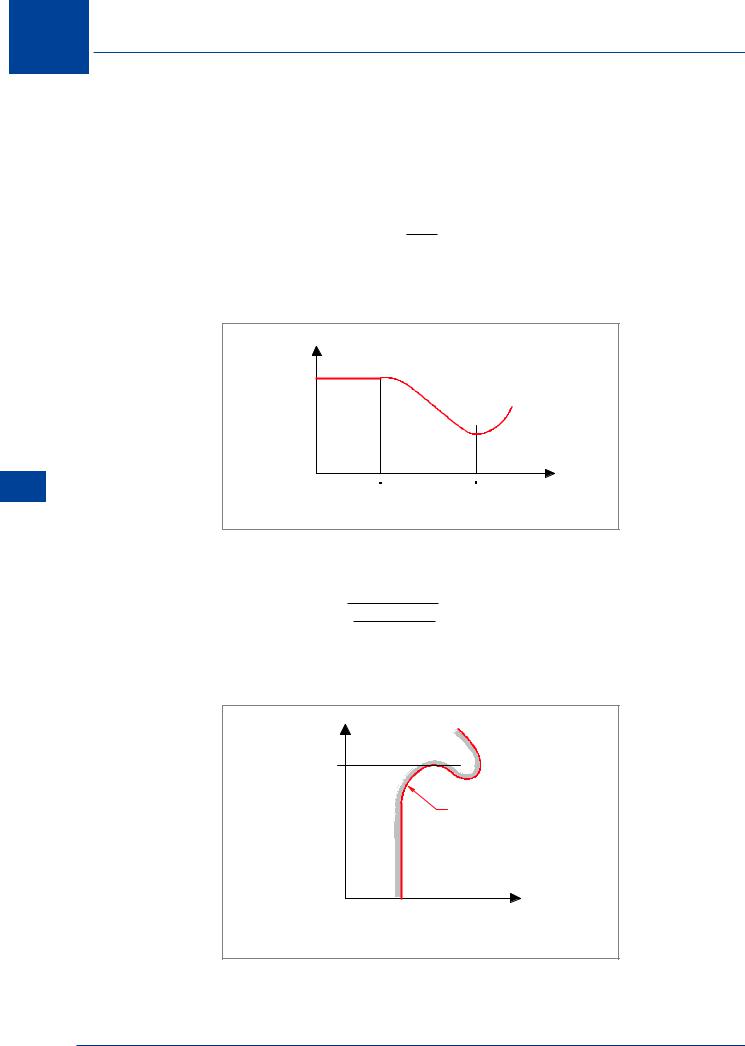
Therefore, if altitude is increased at a constant EAS, Mach number will increase. At low speed CLMAX is fairly constant, but above M 0.4 CLMAX decreases as shown in Figure 13.21. Refer also to Figure 13.12 for the reason why CLMAX starts to decreases at speeds above M 0.4.
CLMAX |
|
|
0 4 |
1 0 |
MFS |
|
|
Figure 13.21
From the 1g stall speed formula:
VS1g = √ ρ L
½ CLMAX S
It can be seen that as CLMAX decreases with increasing altitude, the 1g stall speed will increase.
ALT |
|
ALT 1 |
|
1g |
Stall Speed |
EAS
Figure 13.22
428
High Speed Flight 13
Figure 13.22 shows the variation with altitude of stalling speed at constant load factor (n). Such a curve is called the stall boundary for the given load factor, in which altitude is plotted against equivalent airspeed. At this load factor (1g), the aircraft cannot fly at speeds to the left of this boundary. It is clear that over the lower range of altitude, stall speed does not vary with altitude. This is because at these low altitudes, VS is too low for compressibility effects to be present. Eventually, VS has increased with altitude to such an extent that these effects are important, and the rise in stalling speed with altitude is apparent.
As altitude increases, stall speed is initially constant then increases.
An altitude (Alt1 in Figure 13.22) is eventually reached when there is only one speed at which the aircraft can fly, since increasing or decreasing speed or banking the aircraft will result in a stall. In the case of a 1g manoeuvre, this altitude is called the ‘Aerodynamic Ceiling’. If the aircraft were allowed to ‘drift up’ to this altitude, the aircraft will stall. Not a pleasant prospect for a modern high speed jet transport aircraft. This state of difficulty is also called ‘coffin corner’. Refer also to Figure 13.25.
Note: The recovery in CLMAX at supersonic speeds is such that it may still be possible to operate above this ceiling if enough thrust is available to accelerate the aircraft to supersonic speeds at this altitude.
FL
CONSTANT
MACH NUMBER
EAS
Figure 13.23
Load Factor
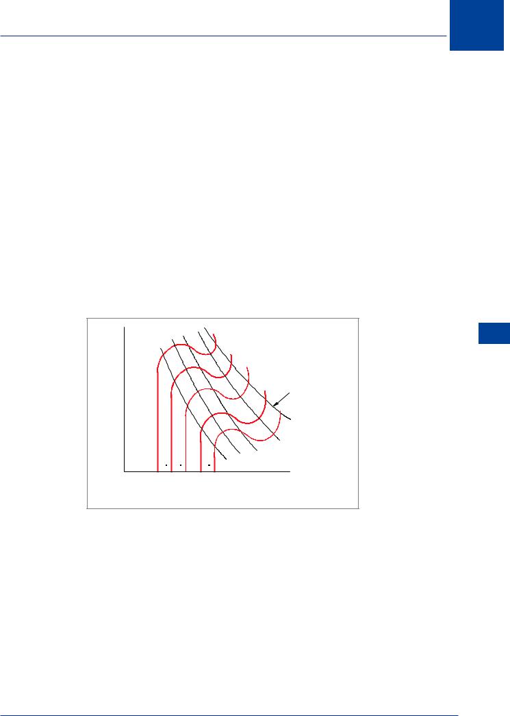
Because load factor increases the stall speed, curves like the one sketched in Figure 13.22 can be drawn for all values of load factor up to the maximum permissible ‘g’, and together they constitute the set of stalling boundaries for the given aircraft. Such a set of curves is shown in Figure 13.23. Superimposed on these curves are dashed lines representing lines of constant Mach number, showing how high Mach numbers can be achieved, even at relatively low EAS, at high altitudes.
High Speed Flight 13
429
13 High Speed Flight
Flight Speed High 13
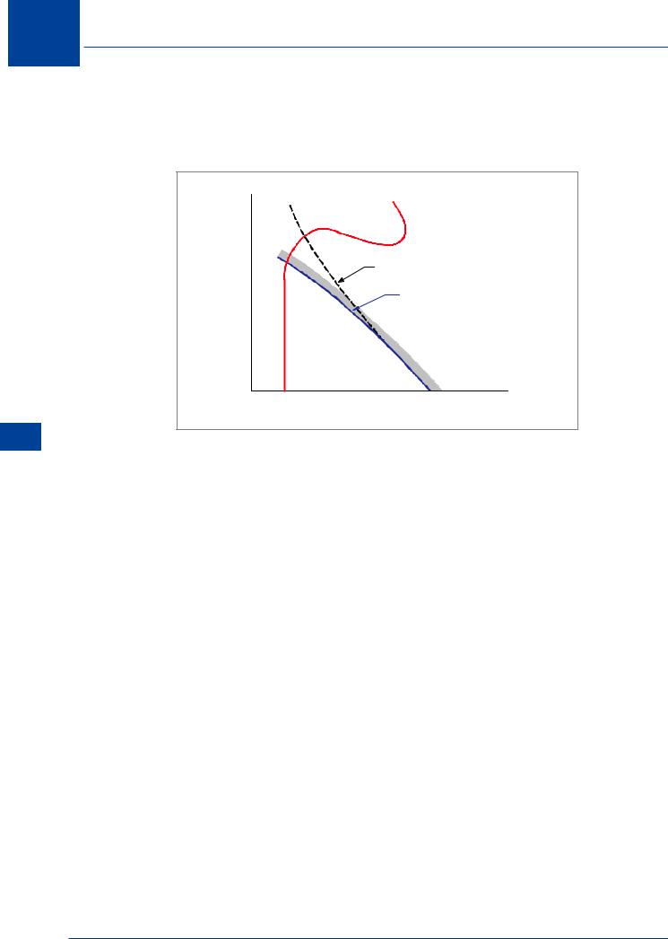
Stall boundaries set a lower limit to the operating speed, according to the load factor. In the case of a high-speed aircraft, there is also an upper limit which is due to the approach of shock stall and the associated buffet which occurs if the aircraft enters the transonic speed range. The limits associated with these effects give the buffet boundaries.
FL
CONSTANT MACH
BUFFET
BOUNDARY
STALL
BOUNDARY
EAS
Figure 13.24
Mach Number
For a given aircraft there is a Mach number which, even at low angle of attack, cannot be exceeded because of the onset of shock stall. Figure 13.23 shows the EAS corresponding to this Mach number falling as altitude increases, so the range of operating speeds is reduced at both ends.
Angle of Attack
However, there is a further effect which makes the buffet boundary a more severe limit than that suggested by a curve of constant Mach number. As the EAS associated with a given Mach number falls with increased altitude, so the required CL, and hence angle of attack, increases. This results in a reduction in the Mach number at which buffeting occurs, which results in a further reduction in the permissible airspeed. This effect is made worse as the high angle of attack stall is approached, and by the time the buffet boundary intersects the stall boundary the limiting Mach number may be well below its value at a lower angle of attack, as Figure 13.24 illustrates.
Also, an increase in load factor (bank angle) requires an increase in lift at a given EAS, hence an increase in angle of attack and a further reduction in limiting Mach number.
Thus the greater the load factor (bank angle or gust), the more severe the limitation due to buffeting.
There is a set of buffet boundaries for various load factors (bank angles), just as there is a set of stall boundaries.
The restrictions on speed and ‘g’ can be summarized in the form of a single diagram in which load factor is plotted against EAS, shown in Figure 13.25.
430
High Speed Flight 13
g |
|
"COFFIN CORNER" |
|
|
MAXIMUM |
|
SEA LEVEL |
|
PERMISSIBLE g |
|
ENVELOPE |
|
STALLING |
AT |
|
|
ALTITUDE |
BUFFET |
|
|
BOUNDARY |
|
BOUNDARY |
1 |
|
|
|
0 |
VS |
|
EAS |
|
|
|
Figure 13.25
Pressure Altitude
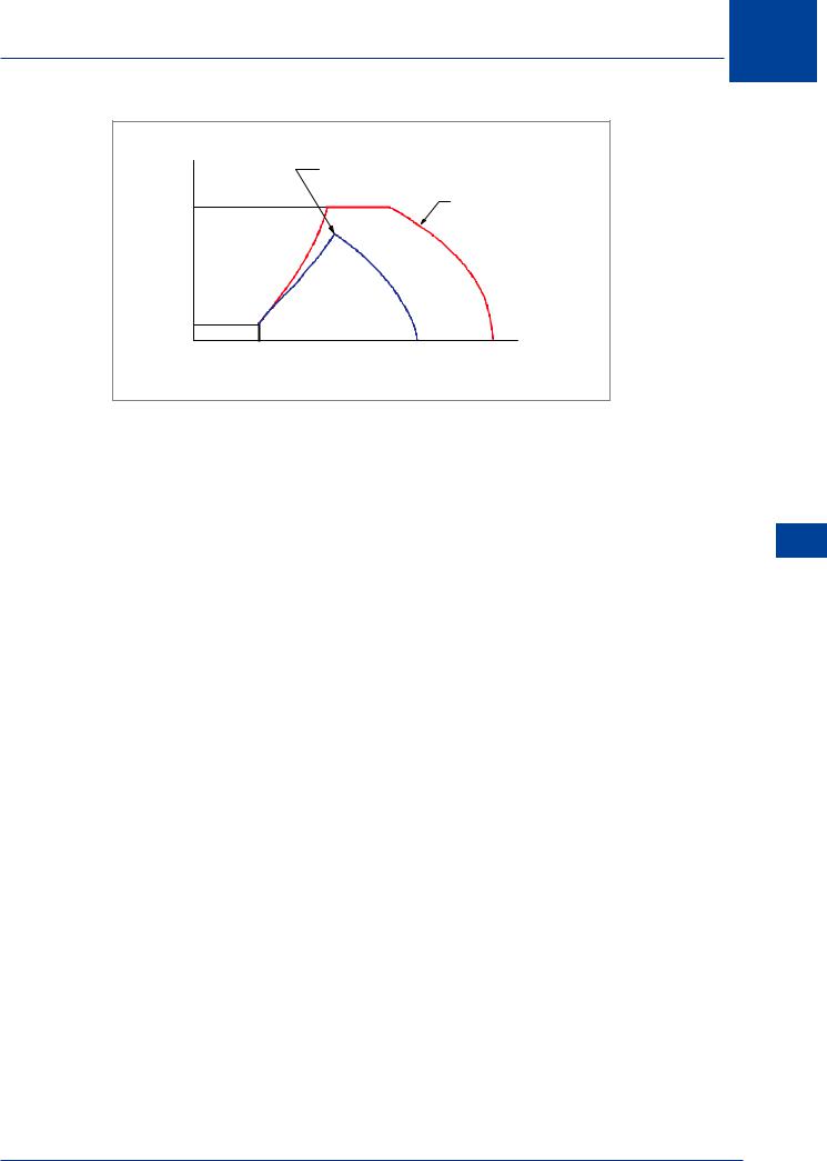
At sea level there is a stall speed below which the aircraft cannot fly. As load factor increases, so does the stall speed (proportional to the square root of the load factor). The curve of ‘g’ against EAS modifies the low speed stall boundary. It will continue to rise until the ‘limit load factor’ is reached (Chapt. 14). The ‘limit load factor’ must never be exceeded. At the high speed end, when g = 1, there is a limiting speed which must not be exceeded because of shock induced buffet. As the load factor increases, so does the CL at given speed, and the limiting Mach number falls, slowly at first and then more rapidly. This defines a buffet boundary, which eventually intersects the boundary of maximum permissible ‘g’ to constitute an overall envelope like the outer curve depicted in Figure 13.25. Thus the aircraft may operate at any combination of speed and load factor within this envelope, but not outside it.
At altitude the situation is similar. However, at altitude the equivalent stalling speed increases
with ‘g’ rather more rapidly than at sea level, because of the Mach number effect on CLMAX. Also, the buffet boundary becomes much more severe.
Above a certain altitude the buffet boundary may intersect the stall boundary at a value of ‘g’ lower than the structural limit, as shown in Figure 13.25. This ‘point’ is another representation of “coffin corner”.
Weight
The weight of the aircraft also affects the envelope. An increase in weight results in an increase in stall speed, and the stall boundary is moved to the right. It also results in an increase in angle of attack at any given speed, so that the Mach number at which buffeting occurs is reduced, and the buffet boundary is moved to the left. Finally, increase in weight implies a reduction in the maximum permissible ‘g’. Thus all the boundaries are made more restrictive by an increase in weight.
CG Position
Forward movement of the CG increases stall speed so the buffet boundaries will be affected in a similar way to that due to weight increase.
High Speed Flight 13
431