

- •Textbook Series
- •Contents
- •1 Overview and Definitions
- •Overview
- •General Definitions
- •Glossary
- •List of Symbols
- •Greek Symbols
- •Others
- •Self-assessment Questions
- •Answers
- •2 The Atmosphere
- •Introduction
- •The Physical Properties of Air
- •Static Pressure
- •Temperature
- •Air Density
- •International Standard Atmosphere (ISA)
- •Dynamic Pressure
- •Key Facts
- •Measuring Dynamic Pressure
- •Relationships between Airspeeds
- •Airspeed
- •Errors and Corrections
- •V Speeds
- •Summary
- •Questions
- •Answers
- •3 Basic Aerodynamic Theory
- •The Principle of Continuity
- •Bernoulli’s Theorem
- •Streamlines and the Streamtube
- •Summary
- •Questions
- •Answers
- •4 Subsonic Airflow
- •Aerofoil Terminology
- •Basics about Airflow
- •Two Dimensional Airflow
- •Summary
- •Questions
- •Answers
- •5 Lift
- •Aerodynamic Force Coefficient
- •The Basic Lift Equation
- •Review:
- •The Lift Curve
- •Interpretation of the Lift Curve
- •Density Altitude
- •Aerofoil Section Lift Characteristics
- •Introduction to Drag Characteristics
- •Lift/Drag Ratio
- •Effect of Aircraft Weight on Minimum Flight Speed
- •Condition of the Surface
- •Flight at High Lift Conditions
- •Three Dimensional Airflow
- •Wing Terminology
- •Wing Tip Vortices
- •Wake Turbulence: (Ref: AIC P 072/2010)
- •Ground Effect
- •Conclusion
- •Summary
- •Answers from page 77
- •Answers from page 78
- •Questions
- •Answers
- •6 Drag
- •Introduction
- •Parasite Drag
- •Induced Drag
- •Methods of Reducing Induced Drag
- •Effect of Lift on Parasite Drag
- •Aeroplane Total Drag
- •The Effect of Aircraft Gross Weight on Total Drag
- •The Effect of Altitude on Total Drag
- •The Effect of Configuration on Total Drag
- •Speed Stability
- •Power Required (Introduction)
- •Summary
- •Questions
- •Annex C
- •Answers
- •7 Stalling
- •Introduction
- •Cause of the Stall
- •The Lift Curve
- •Stall Recovery
- •Aircraft Behaviour Close to the Stall
- •Use of Flight Controls Close to the Stall
- •Stall Recognition
- •Stall Speed
- •Stall Warning
- •Artificial Stall Warning Devices
- •Basic Stall Requirements (EASA and FAR)
- •Wing Design Characteristics
- •The Effect of Aerofoil Section
- •The Effect of Wing Planform
- •Key Facts 1
- •Super Stall (Deep Stall)
- •Factors that Affect Stall Speed
- •1g Stall Speed
- •Effect of Weight Change on Stall Speed
- •Composition and Resolution of Forces
- •Using Trigonometry to Resolve Forces
- •Lift Increase in a Level Turn
- •Effect of Load Factor on Stall Speed
- •Effect of High Lift Devices on Stall Speed
- •Effect of CG Position on Stall Speed
- •Effect of Landing Gear on the Stall Speed
- •Effect of Engine Power on Stall Speed
- •Effect of Mach Number (Compressibility) on Stall Speed
- •Effect of Wing Contamination on Stall Speed
- •Warning to the Pilot of Icing-induced Stalls
- •Stabilizer Stall Due to Ice
- •Effect of Heavy Rain on Stall Speed
- •Stall and Recovery Characteristics of Canards
- •Spinning
- •Primary Causes of a Spin
- •Phases of a Spin
- •The Effect of Mass and Balance on Spins
- •Spin Recovery
- •Special Phenomena of Stall
- •High Speed Buffet (Shock Stall)
- •Answers to Questions on Page 173
- •Key Facts 2
- •Questions
- •Key Facts 1 (Completed)
- •Key Facts 2 (Completed)
- •Answers
- •8 High Lift Devices
- •Purpose of High Lift Devices
- •Take-off and Landing Speeds
- •Augmentation
- •Flaps
- •Trailing Edge Flaps
- •Plain Flap
- •Split Flap
- •Slotted and Multiple Slotted Flaps
- •The Fowler Flap
- •Comparison of Trailing Edge Flaps
- •and Stalling Angle
- •Drag
- •Lift / Drag Ratio
- •Pitching Moment
- •Centre of Pressure Movement
- •Change of Downwash
- •Overall Pitch Change
- •Aircraft Attitude with Flaps Lowered
- •Leading Edge High Lift Devices
- •Leading Edge Flaps
- •Effect of Leading Edge Flaps on Lift
- •Leading Edge Slots
- •Leading Edge Slat
- •Automatic Slots
- •Disadvantages of the Slot
- •Drag and Pitching Moment of Leading Edge Devices
- •Trailing Edge Plus Leading Edge Devices
- •Sequence of Operation
- •Asymmetry of High Lift Devices
- •Flap Load Relief System
- •Choice of Flap Setting for Take-off, Climb and Landing
- •Management of High Lift Devices
- •Flap Extension Prior to Landing
- •Questions
- •Annexes
- •Answers
- •9 Airframe Contamination
- •Introduction
- •Types of Contamination
- •Effect of Frost and Ice on the Aircraft
- •Effect on Instruments
- •Effect on Controls
- •Water Contamination
- •Airframe Aging
- •Questions
- •Answers
- •10 Stability and Control
- •Introduction
- •Static Stability
- •Aeroplane Reference Axes
- •Static Longitudinal Stability
- •Neutral Point
- •Static Margin
- •Trim and Controllability
- •Key Facts 1
- •Graphic Presentation of Static Longitudinal Stability
- •Contribution of the Component Surfaces
- •Power-off Stability
- •Effect of CG Position
- •Power Effects
- •High Lift Devices
- •Control Force Stability
- •Manoeuvre Stability
- •Stick Force Per ‘g’
- •Tailoring Control Forces
- •Longitudinal Control
- •Manoeuvring Control Requirement
- •Take-off Control Requirement
- •Landing Control Requirement
- •Dynamic Stability
- •Longitudinal Dynamic Stability
- •Long Period Oscillation (Phugoid)
- •Short Period Oscillation
- •Directional Stability and Control
- •Sideslip Angle
- •Static Directional Stability
- •Contribution of the Aeroplane Components.
- •Lateral Stability and Control
- •Static Lateral Stability
- •Contribution of the Aeroplane Components
- •Lateral Dynamic Effects
- •Spiral Divergence
- •Dutch Roll
- •Pilot Induced Oscillation (PIO)
- •High Mach Numbers
- •Mach Trim
- •Key Facts 2
- •Summary
- •Questions
- •Key Facts 1 (Completed)
- •Key Facts 2 (Completed)
- •Answers
- •11 Controls
- •Introduction
- •Hinge Moments
- •Control Balancing
- •Mass Balance
- •Longitudinal Control
- •Lateral Control
- •Speed Brakes
- •Directional Control
- •Secondary Effects of Controls
- •Trimming
- •Questions
- •Answers
- •12 Flight Mechanics
- •Introduction
- •Straight Horizontal Steady Flight
- •Tailplane and Elevator
- •Balance of Forces
- •Straight Steady Climb
- •Climb Angle
- •Effect of Weight, Altitude and Temperature.
- •Power-on Descent
- •Emergency Descent
- •Glide
- •Rate of Descent in the Glide
- •Turning
- •Flight with Asymmetric Thrust
- •Summary of Minimum Control Speeds
- •Questions
- •Answers
- •13 High Speed Flight
- •Introduction
- •Speed of Sound
- •Mach Number
- •Effect on Mach Number of Climbing at a Constant IAS
- •Variation of TAS with Altitude at a Constant Mach Number
- •Influence of Temperature on Mach Number at a Constant Flight Level and IAS
- •Subdivisions of Aerodynamic Flow
- •Propagation of Pressure Waves
- •Normal Shock Waves
- •Critical Mach Number
- •Pressure Distribution at Transonic Mach Numbers
- •Properties of a Normal Shock Wave
- •Oblique Shock Waves
- •Effects of Shock Wave Formation
- •Buffet
- •Factors Which Affect the Buffet Boundaries
- •The Buffet Margin
- •Use of the Buffet Onset Chart
- •Delaying or Reducing the Effects of Compressibility
- •Aerodynamic Heating
- •Mach Angle
- •Mach Cone
- •Area (Zone) of Influence
- •Bow Wave
- •Expansion Waves
- •Sonic Bang
- •Methods of Improving Control at Transonic Speeds
- •Questions
- •Answers
- •14 Limitations
- •Operating Limit Speeds
- •Loads and Safety Factors
- •Loads on the Structure
- •Load Factor
- •Boundary
- •Design Manoeuvring Speed, V
- •Effect of Altitude on V
- •Effect of Aircraft Weight on V
- •Design Cruising Speed V
- •Design Dive Speed V
- •Negative Load Factors
- •The Negative Stall
- •Manoeuvre Boundaries
- •Operational Speed Limits
- •Gust Loads
- •Effect of a Vertical Gust on the Load Factor
- •Effect of the Gust on Stalling
- •Operational Rough-air Speed (V
- •Landing Gear Speed Limitations
- •Flap Speed Limit
- •Aeroelasticity (Aeroelastic Coupling)
- •Flutter
- •Control Surface Flutter
- •Aileron Reversal
- •Questions
- •Answers
- •15 Windshear
- •Introduction (Ref: AIC 84/2008)
- •Microburst
- •Windshear Encounter during Approach
- •Effects of Windshear
- •“Typical” Recovery from Windshear
- •Windshear Reporting
- •Visual Clues
- •Conclusions
- •Questions
- •Answers
- •16 Propellers
- •Introduction
- •Definitions
- •Aerodynamic Forces on the Propeller
- •Thrust
- •Centrifugal Twisting Moment (CTM)
- •Propeller Efficiency
- •Variable Pitch Propellers
- •Power Absorption
- •Moments and Forces Generated by a Propeller
- •Effect of Atmospheric Conditions
- •Questions
- •Answers
- •17 Revision Questions
- •Questions
- •Answers
- •Explanations to Specimen Questions
- •Specimen Examination Paper
- •Answers to Specimen Exam Paper
- •Explanations to Specimen Exam Paper
- •18 Index
11 Controls
Mass Balance
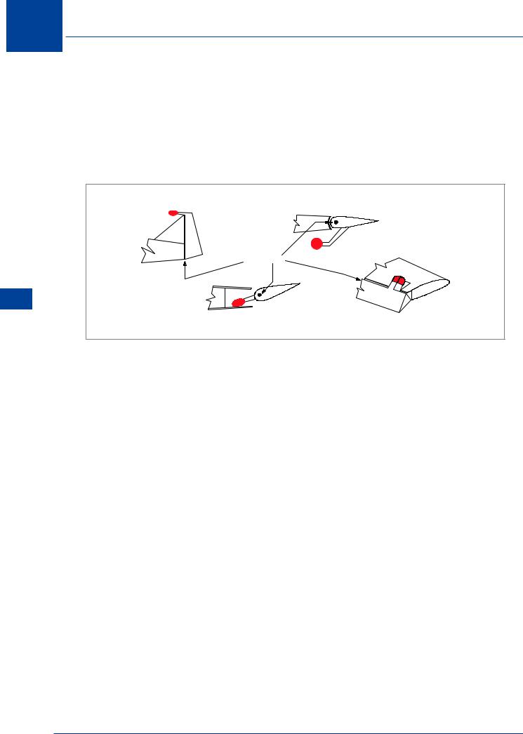
Mass balance is a WEIGHT attached to the control surface forward of the hinge. Most control surfaces are mass balanced. The purpose of this is to prevent control surface flutter. Flutter is an oscillation of the control surface which can occur due to the bending and twisting of the structure under load. If the control surface CG is behind the hinge line, inertia will cause the surface to oscillate about its hinge line. The oscillations can be divergent and cause structural failure. A detailed explanation of flutter is given in Chapter 14.
HINGE LINE
Controls 11
Figure 11.15 Mass balance weights
Flutter may be prevented by adding weight to the control surface in front of the hinge line. This brings the centre of gravity of the control forward to a position on, or slightly in front of the hinge, but always to the point required by the designers . This reduces the inertia moments about the hinge and prevents flutter developing. Figure 11.15 illustrates some common methods of mass balancing.
Longitudinal Control
Control in pitch is usually obtained by elevators or by an all moving (slab) tailplane, and the controls must be adequate to balance the aircraft throughout its speed range at all permitted CG positions and configurations and to give an adequate rate of pitch for manoeuvres.
Effect of Elevator Deflection
Suppose that the aircraft is flying in balance at a steady speed with the elevator neutral. If the elevator is deflected upwards, the tail will develop a down load which will begin to pitch the aircraft nose upwards. As the angle of attack increases, the tailplane down load decreases and the aircraft will reach an equilibrium pitch position. It will then remain in that pitch position with the elevator kept at the selected angle. If the elevator is returned to neutral, the tail will develop an upload which will begin to pitch the aeroplane down again. At a given CG position there will be a given pitch attitude for each elevator position.
340

Controls 11
Direction of theTailplane Load
The elevator angle required to give balance depends on IAS and the CG position. At normal cruising speeds and CG positions, the elevator should ideally be approximately neutral. The tailplane will be giving a down load and, consequently, a nose-up pitching moment. This will balance the nose-down moment created by the wing with its centre of pressure fairly well aft. At higher than normal speeds, the CP will move further rearwards giving a stronger nosedown pitch and needing a larger down-load from the tailplane. However, at higher speed the aircraft’s angle of attack will be decreased, requiring some down elevator to provide the correct tail-load.
At lower than normal speeds, the CP will move forward and the wing and fuselage may cause a nose-up pitching moment. The tailplane will be required to give an up-load for balance. At low speed, the aircraft will be at a high angle of attack, and to reach this attitude, the elevator will have been moved up.
Elevator Angle with ‘g’
When the aircraft is performing a pitching manoeuvre, the tailplane angle of attack is increased by the effect of the rotational velocity and the aerodynamic damping is increased. This means that a larger elevator angle will be required than for the same conditions in 1g flight. The additional elevator angle required will be proportional to the ‘g’ being experienced. The elevator movement available should be sufficient to allow the design limit ‘g’ to be reached.
The most demanding requirement for elevator up authority will be when the aircraft is being flared for landing, in ground effect with most forward CG.
Effect of Ice on theTailplane
The tailplane is an aerofoil, usually symmetrical as it is required to produce both up and down loads. It is set at an angle of incidence which is less than that of the wing. This ensures that it will not stall before the wing, and so control can be maintained up to the stall. It is usually affected by the downwash from the wing and this reduces its effective angle of attack. Typically the tail will be at a negative angle of attack, producing a down load for balance. If ice forms on the tailplane leading edge, its aerofoil shape will be distorted, and its stalling angle reduced. This could cause the tailplane to stall, particularly if the downwash is increased as a result of lowering flaps. With the tailplane stalled its down load would be reduced, and the aircraft would pitch down and could not be recovered.
Lateral Control
Control in roll is usually obtained by ailerons or by spoilers, or by a combination of the two. The main requirement for lateral control is to achieve an adequate rate of roll.
On the ground with the control wheel in the neutral position both ailerons should be slightly below alignment with the wing trailing edge, or “drooped”. When airborne, the lower pressure on the top surface will “suck” both ailerons up into a position where they are perfectly aligned with the wing trailing edge, thus reducing drag.
Controls 11
341
11
Controls 11
Controls
Effect of Aileron Deflection (Aerodynamic Damping)
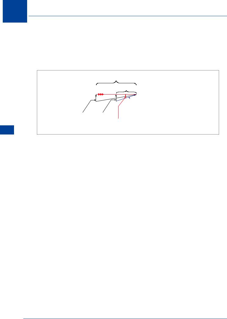
In steady level flight with the ailerons neutral, the lift on the two wings will be equal. If the control wheel is turned to the left, the left aileron will move up and the right aileron down. The up aileron will decrease the lift of the left wing which will begin to ‘drop’. The downward movement of the wing creates a relative airflow upwards, which increases its effective angle of attack. The opposite effects will occur on the right (up-going) wing.
HIGH TAS
LOW TAS
 RELATIVE AIRFLOW
FROM ANGULAR ROTATION
EQUAL WING TIP VELOCITY
INCREASE IN EFFECTIVE ANGLE OF ATTACK
DUE TO WING TIP DOWNWARDS VELOCITY
Figure 11.16 Aerodynamic damping in roll
The increased effective angle of attack of the down-going wing increases its lift, which opposes the roll. This is called aerodynamic damping. The greater the rate of roll, the greater the damping. It can also be seen from Figure 11.16 that the greater the TAS, the smaller the increase in effective angle of attack for a given roll rate.
The change in wing lift for a given aileron deflection depends on the IAS, but the change of effective angle of attack due to roll velocity depends on TAS. At high TAS (constant IAS, higher altitude) the change in effective angle of attack will be reduced and a higher rate of roll will be possible. Rate of roll therefore increases (aerodynamic damping decreases) with higher TAS for a given aileron deflection. The aileron is known as a rate control since a given aileron angle of deflection determines a rate of roll, not a roll displacement.
Effect of Wingspan on Rate of Roll
For a given rate of roll, the wing tip rolling velocity will increase with the wingspan. Aerodynamic damping will therefore be greater if the span is greater. Under the same conditions, a short span wing will have a greater rate of roll than a large span wing.
Adverse Aileron Yaw
The ailerons produce a rolling moment by increasing the lift on one wing and decreasing it on the other. The increased lift on the up-going wing gives an increase in the induced drag, whereas the reduced lift on the down-going wing gives a decease in induced drag. The difference in drag on the two wings produces a yawing moment which is opposite to the rolling moment, that is, a roll to the left produces a yawing moment to the right. This is known as adverse aileron yaw.
342
Controls 11
Reducing Adverse Aileron Yaw
LARGE
UPWARD
MOVEMENT
SMALL
DOWNWARD
MOVEMENT
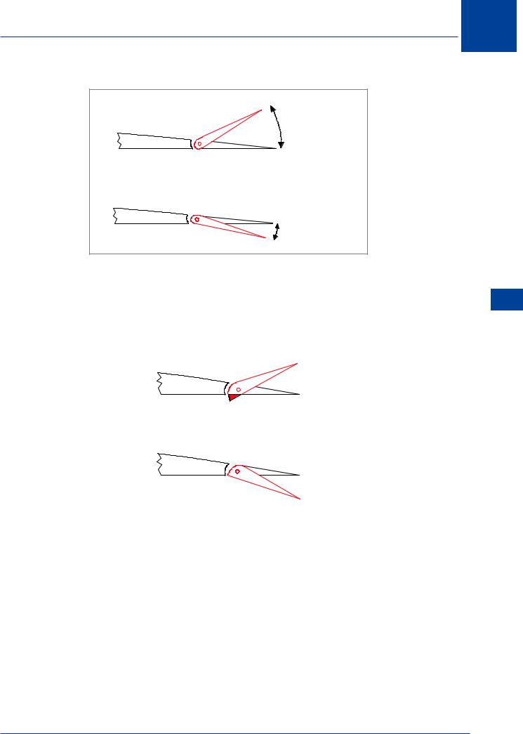
Figure 11.17 Differential ailerons
• Differential ailerons: The aileron linkage causes the up-going aileron to move through a |
11 |
|||
larger angle than the down-going aileron, Figure 11.17. This increases the drag on the up |
||||
aileron and reduces it on the down aileron, and so reduces the difference in drag between |
Controls |
|||
the two wings. |
||||
|
||||
|
|
|
|
|
|
|
|
|
|
Figure 11.18 Frise ailerons
•Frise ailerons: These have an asymmetric leading edge, as illustrated in Figure 11.18. The leading edge of the up-going aileron protrudes below the lower surface of the wing, causing high drag. The leading edge of the down-going aileron remains shrouded and causes less drag.
•Aileron-rudder coupling: In this system the aileron and rudder controls are interconnected, so that when the ailerons are deflected, the rudder automatically moves to counter the adverse yaw.
•Roll control spoilers: If roll spoilers are used to augment the roll rate obtained from the ailerons, they will reduce the adverse yaw, as the down-going wing will have an increase in drag due to the raised spoiler.
343
11 Controls
Inboard Ailerons
Ailerons are normally situated at the wing tips to give the greatest rolling moment for the force produced. However, this means they are also able to generate the maximum twisting loads on the wing. For instance, a down-going aileron will twist the wing tip and decrease wing tip incidence. The wing is not a rigid structure and any twist will cause a decrease of aileron effectiveness. As IAS increases, a down-going aileron will give more wing twist (decreased wing tip incidence). Eventually, an IAS will be reached at which the decrease in tip incidence will give a larger downforce than the upforce produced by the aileron. This is called high speed “aileron reversal”; the wing will go down, rather than up as the pilot intended. To reduce this effect, the ailerons could be mounted further inboard. Unfortunately, this would reduce aileron effectiveness at low speed.
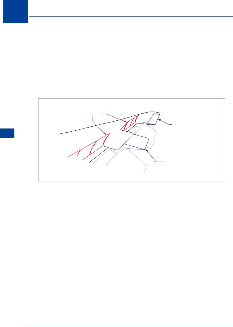
SPOILER SURFACES
(LIFT DUMP POSITION)
OUTBOARD AILERONS
(LOW SPEED ONLY)
Controls 11
INBOARD AILERONS
(HIGH SPEED AND LOW SPEED)
Figure 11.19 Inboard & outboard ailerons & spoiler surfaces
Alternatively, two sets of ailerons may be fitted, as illustrated in Figure 11.19: one set at the wing tips for use only at low speeds when the forces involved are low, and one set inboard for use at high speeds when the forces are greater and could cause greater structural distortion. Outboard (low speed) ailerons are “locked-out” as the flaps retract. At low speed both sets of ailerons work, but at high speed only the inboard ailerons respond to control input.
Flaperons
The flaps and the ailerons both occupy part of the wing trailing edge. For good take-off and landing performance, the flaps need to be as large as possible, and for a good rate of roll, the ailerons need to be as large as possible. However, the space available is limited, and one solution is to droop the ailerons symmetrically to augment the flap area. They then move differentially from the drooped position to give lateral control. Another system is to use the trailing edge moveable surfaces to perform the operation of both flaps and ailerons.
344
Controls
Roll Control Spoilers
Spoilers may be used to give lateral control, in addition to, or instead of ailerons. Spoilers consist of movable panels on the upper wing surface, hinged at their forward edge, which can be raised hydraulically, as illustrated in Figure 11.20. A raised spoiler will disturb the airflow over the wing and reduce lift.
OUTBOARD AILERONS |
SPOILER SURFACES ASSISTING |
|
WITH ROLL CONTROL |
||
LOCKED - OUT AT |
||
|
||
HIGH SPEED |
|
INBOARD AILERONS OPERATE
AT ALL SPEEDS
Figure 11.20 Roll control spoilers
To function as a lateral control, the spoilers rise on the wing with the up-going aileron (downgoing wing), proportional to aileron input. On the wing with the down-going aileron, they remain flush. Unlike ailerons, spoilers cannot give an increase of lift, so a roll manoeuvre controlled by spoilers will always give a net loss of lift. However, the spoiler has several advantages compared to the aileron:
•There is no adverse yaw: The raised spoiler increases drag on that wing, so the yaw is in the same direction as the roll.
•Wing twisting is reduced: The aerodynamic force on the spoilers acts further forward than is the case with ailerons, reducing the moment which tends to twist the wing.
•At transonic speed its effectiveness is not reduced by shock induced separation.
•It cannot develop flutter.
•Spoilers do not occupy the trailing edge, which can then be utilized for flaps.
11
Controls 11
345