

- •Textbook Series
- •Contents
- •1 Overview and Definitions
- •Overview
- •General Definitions
- •Glossary
- •List of Symbols
- •Greek Symbols
- •Others
- •Self-assessment Questions
- •Answers
- •2 The Atmosphere
- •Introduction
- •The Physical Properties of Air
- •Static Pressure
- •Temperature
- •Air Density
- •International Standard Atmosphere (ISA)
- •Dynamic Pressure
- •Key Facts
- •Measuring Dynamic Pressure
- •Relationships between Airspeeds
- •Airspeed
- •Errors and Corrections
- •V Speeds
- •Summary
- •Questions
- •Answers
- •3 Basic Aerodynamic Theory
- •The Principle of Continuity
- •Bernoulli’s Theorem
- •Streamlines and the Streamtube
- •Summary
- •Questions
- •Answers
- •4 Subsonic Airflow
- •Aerofoil Terminology
- •Basics about Airflow
- •Two Dimensional Airflow
- •Summary
- •Questions
- •Answers
- •5 Lift
- •Aerodynamic Force Coefficient
- •The Basic Lift Equation
- •Review:
- •The Lift Curve
- •Interpretation of the Lift Curve
- •Density Altitude
- •Aerofoil Section Lift Characteristics
- •Introduction to Drag Characteristics
- •Lift/Drag Ratio
- •Effect of Aircraft Weight on Minimum Flight Speed
- •Condition of the Surface
- •Flight at High Lift Conditions
- •Three Dimensional Airflow
- •Wing Terminology
- •Wing Tip Vortices
- •Wake Turbulence: (Ref: AIC P 072/2010)
- •Ground Effect
- •Conclusion
- •Summary
- •Answers from page 77
- •Answers from page 78
- •Questions
- •Answers
- •6 Drag
- •Introduction
- •Parasite Drag
- •Induced Drag
- •Methods of Reducing Induced Drag
- •Effect of Lift on Parasite Drag
- •Aeroplane Total Drag
- •The Effect of Aircraft Gross Weight on Total Drag
- •The Effect of Altitude on Total Drag
- •The Effect of Configuration on Total Drag
- •Speed Stability
- •Power Required (Introduction)
- •Summary
- •Questions
- •Annex C
- •Answers
- •7 Stalling
- •Introduction
- •Cause of the Stall
- •The Lift Curve
- •Stall Recovery
- •Aircraft Behaviour Close to the Stall
- •Use of Flight Controls Close to the Stall
- •Stall Recognition
- •Stall Speed
- •Stall Warning
- •Artificial Stall Warning Devices
- •Basic Stall Requirements (EASA and FAR)
- •Wing Design Characteristics
- •The Effect of Aerofoil Section
- •The Effect of Wing Planform
- •Key Facts 1
- •Super Stall (Deep Stall)
- •Factors that Affect Stall Speed
- •1g Stall Speed
- •Effect of Weight Change on Stall Speed
- •Composition and Resolution of Forces
- •Using Trigonometry to Resolve Forces
- •Lift Increase in a Level Turn
- •Effect of Load Factor on Stall Speed
- •Effect of High Lift Devices on Stall Speed
- •Effect of CG Position on Stall Speed
- •Effect of Landing Gear on the Stall Speed
- •Effect of Engine Power on Stall Speed
- •Effect of Mach Number (Compressibility) on Stall Speed
- •Effect of Wing Contamination on Stall Speed
- •Warning to the Pilot of Icing-induced Stalls
- •Stabilizer Stall Due to Ice
- •Effect of Heavy Rain on Stall Speed
- •Stall and Recovery Characteristics of Canards
- •Spinning
- •Primary Causes of a Spin
- •Phases of a Spin
- •The Effect of Mass and Balance on Spins
- •Spin Recovery
- •Special Phenomena of Stall
- •High Speed Buffet (Shock Stall)
- •Answers to Questions on Page 173
- •Key Facts 2
- •Questions
- •Key Facts 1 (Completed)
- •Key Facts 2 (Completed)
- •Answers
- •8 High Lift Devices
- •Purpose of High Lift Devices
- •Take-off and Landing Speeds
- •Augmentation
- •Flaps
- •Trailing Edge Flaps
- •Plain Flap
- •Split Flap
- •Slotted and Multiple Slotted Flaps
- •The Fowler Flap
- •Comparison of Trailing Edge Flaps
- •and Stalling Angle
- •Drag
- •Lift / Drag Ratio
- •Pitching Moment
- •Centre of Pressure Movement
- •Change of Downwash
- •Overall Pitch Change
- •Aircraft Attitude with Flaps Lowered
- •Leading Edge High Lift Devices
- •Leading Edge Flaps
- •Effect of Leading Edge Flaps on Lift
- •Leading Edge Slots
- •Leading Edge Slat
- •Automatic Slots
- •Disadvantages of the Slot
- •Drag and Pitching Moment of Leading Edge Devices
- •Trailing Edge Plus Leading Edge Devices
- •Sequence of Operation
- •Asymmetry of High Lift Devices
- •Flap Load Relief System
- •Choice of Flap Setting for Take-off, Climb and Landing
- •Management of High Lift Devices
- •Flap Extension Prior to Landing
- •Questions
- •Annexes
- •Answers
- •9 Airframe Contamination
- •Introduction
- •Types of Contamination
- •Effect of Frost and Ice on the Aircraft
- •Effect on Instruments
- •Effect on Controls
- •Water Contamination
- •Airframe Aging
- •Questions
- •Answers
- •10 Stability and Control
- •Introduction
- •Static Stability
- •Aeroplane Reference Axes
- •Static Longitudinal Stability
- •Neutral Point
- •Static Margin
- •Trim and Controllability
- •Key Facts 1
- •Graphic Presentation of Static Longitudinal Stability
- •Contribution of the Component Surfaces
- •Power-off Stability
- •Effect of CG Position
- •Power Effects
- •High Lift Devices
- •Control Force Stability
- •Manoeuvre Stability
- •Stick Force Per ‘g’
- •Tailoring Control Forces
- •Longitudinal Control
- •Manoeuvring Control Requirement
- •Take-off Control Requirement
- •Landing Control Requirement
- •Dynamic Stability
- •Longitudinal Dynamic Stability
- •Long Period Oscillation (Phugoid)
- •Short Period Oscillation
- •Directional Stability and Control
- •Sideslip Angle
- •Static Directional Stability
- •Contribution of the Aeroplane Components.
- •Lateral Stability and Control
- •Static Lateral Stability
- •Contribution of the Aeroplane Components
- •Lateral Dynamic Effects
- •Spiral Divergence
- •Dutch Roll
- •Pilot Induced Oscillation (PIO)
- •High Mach Numbers
- •Mach Trim
- •Key Facts 2
- •Summary
- •Questions
- •Key Facts 1 (Completed)
- •Key Facts 2 (Completed)
- •Answers
- •11 Controls
- •Introduction
- •Hinge Moments
- •Control Balancing
- •Mass Balance
- •Longitudinal Control
- •Lateral Control
- •Speed Brakes
- •Directional Control
- •Secondary Effects of Controls
- •Trimming
- •Questions
- •Answers
- •12 Flight Mechanics
- •Introduction
- •Straight Horizontal Steady Flight
- •Tailplane and Elevator
- •Balance of Forces
- •Straight Steady Climb
- •Climb Angle
- •Effect of Weight, Altitude and Temperature.
- •Power-on Descent
- •Emergency Descent
- •Glide
- •Rate of Descent in the Glide
- •Turning
- •Flight with Asymmetric Thrust
- •Summary of Minimum Control Speeds
- •Questions
- •Answers
- •13 High Speed Flight
- •Introduction
- •Speed of Sound
- •Mach Number
- •Effect on Mach Number of Climbing at a Constant IAS
- •Variation of TAS with Altitude at a Constant Mach Number
- •Influence of Temperature on Mach Number at a Constant Flight Level and IAS
- •Subdivisions of Aerodynamic Flow
- •Propagation of Pressure Waves
- •Normal Shock Waves
- •Critical Mach Number
- •Pressure Distribution at Transonic Mach Numbers
- •Properties of a Normal Shock Wave
- •Oblique Shock Waves
- •Effects of Shock Wave Formation
- •Buffet
- •Factors Which Affect the Buffet Boundaries
- •The Buffet Margin
- •Use of the Buffet Onset Chart
- •Delaying or Reducing the Effects of Compressibility
- •Aerodynamic Heating
- •Mach Angle
- •Mach Cone
- •Area (Zone) of Influence
- •Bow Wave
- •Expansion Waves
- •Sonic Bang
- •Methods of Improving Control at Transonic Speeds
- •Questions
- •Answers
- •14 Limitations
- •Operating Limit Speeds
- •Loads and Safety Factors
- •Loads on the Structure
- •Load Factor
- •Boundary
- •Design Manoeuvring Speed, V
- •Effect of Altitude on V
- •Effect of Aircraft Weight on V
- •Design Cruising Speed V
- •Design Dive Speed V
- •Negative Load Factors
- •The Negative Stall
- •Manoeuvre Boundaries
- •Operational Speed Limits
- •Gust Loads
- •Effect of a Vertical Gust on the Load Factor
- •Effect of the Gust on Stalling
- •Operational Rough-air Speed (V
- •Landing Gear Speed Limitations
- •Flap Speed Limit
- •Aeroelasticity (Aeroelastic Coupling)
- •Flutter
- •Control Surface Flutter
- •Aileron Reversal
- •Questions
- •Answers
- •15 Windshear
- •Introduction (Ref: AIC 84/2008)
- •Microburst
- •Windshear Encounter during Approach
- •Effects of Windshear
- •“Typical” Recovery from Windshear
- •Windshear Reporting
- •Visual Clues
- •Conclusions
- •Questions
- •Answers
- •16 Propellers
- •Introduction
- •Definitions
- •Aerodynamic Forces on the Propeller
- •Thrust
- •Centrifugal Twisting Moment (CTM)
- •Propeller Efficiency
- •Variable Pitch Propellers
- •Power Absorption
- •Moments and Forces Generated by a Propeller
- •Effect of Atmospheric Conditions
- •Questions
- •Answers
- •17 Revision Questions
- •Questions
- •Answers
- •Explanations to Specimen Questions
- •Specimen Examination Paper
- •Answers to Specimen Exam Paper
- •Explanations to Specimen Exam Paper
- •18 Index

10 Stability and Control
Directional Stability and Control
Control and Stability 10
The directional stability of an aeroplane is essentially the “weathercock” stability and involves moments about the normal axis and their relationship with yaw or sideslip angle. An aeroplane which has static directional stability will tend to return to equilibrium when subjected to some disturbance. Evidence of static directional stability would be the development of yawing moments which tend to restore the aeroplane to equilibrium.
Definitions
The axis system of an aeroplane defines a positive yawing moment, N, as a moment about the normal axis which tends to rotate the nose to the right. As in other aerodynamic considerations, it is convenient to consider yawing moments in the coefficient form so that static stability can be evaluated independent of weight, altitude, speed, etc. The yawing moment, N, is defined in the coefficient form by the following equation:
|
N |
= Cn Q S b |
|||
or |
|
|
|
|
|
|
Cn |
= |
|
N |
|
|
|
Q S b |
|
||
where: |
|
|
|
|
|
N |
= |
|
yawing moment |
||
Q |
= |
|
dynamic pressure |
||
S |
= |
|
wing area |
||
b |
= |
|
wingspan |
||
Cn |
= |
|
yawing moment coefficient (positive to the right) |
||
The yawing moment coefficient, Cn, is based on the wing dimensions S and b as the wing is the characteristic surface of the aeroplane.
290
Stability and Control 10
Sideslip Angle
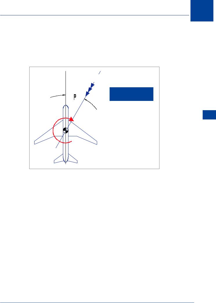
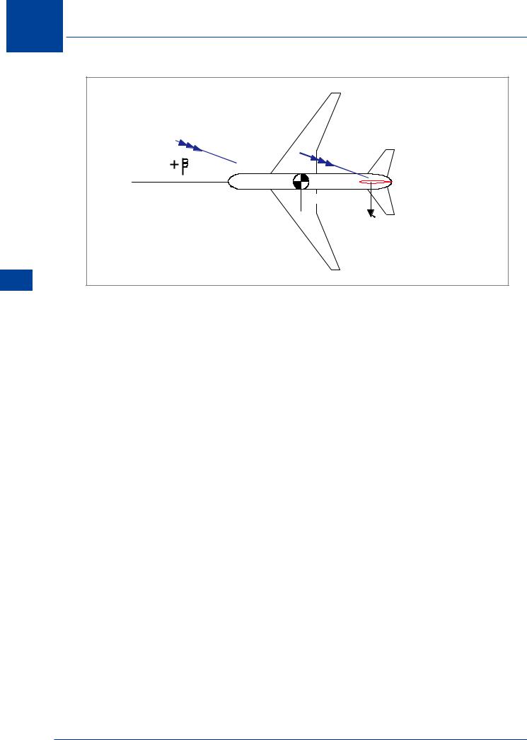
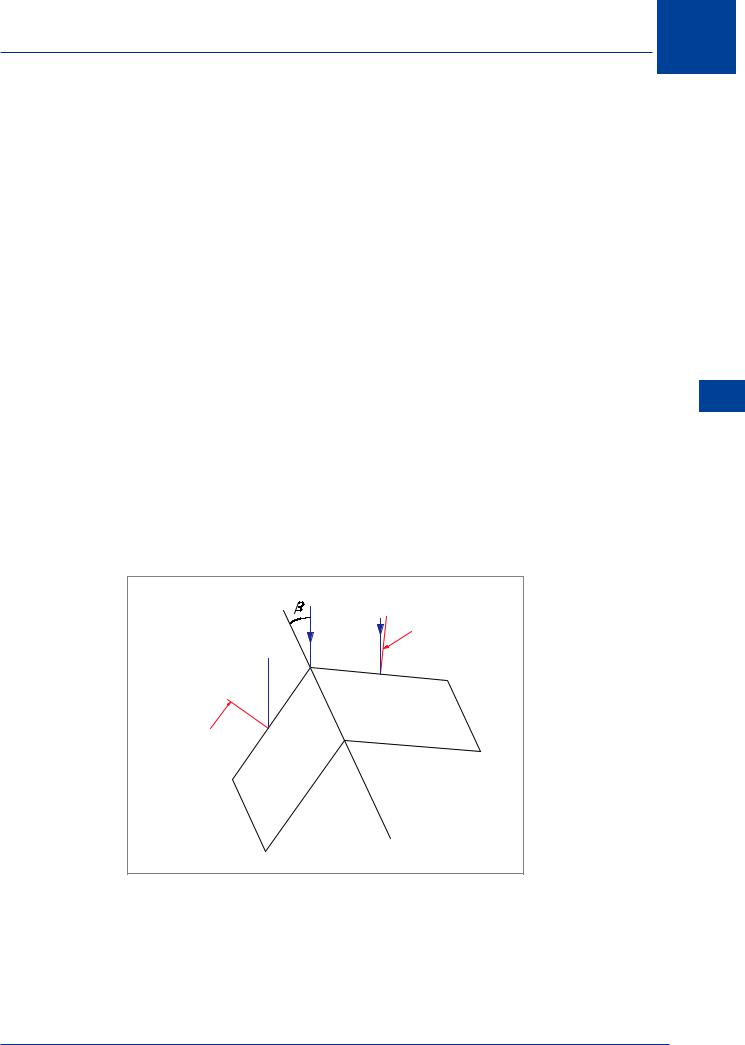
The sideslip angle relates the displacement of the aeroplane centre line from the relative airflow. Sideslip angle is provided the symbol β (beta) and is positive when the relative wind is displaced to the right of the aeroplane centre line. Figure 10.54 illustrates the definition of sideslip angle.
RELATIVE
AIRFLOW
A YAW TO THE LEFT GIVES
A SIDESLIP TO THE RIGHT
SIDESLIP
ANGLE
 N, YAWING MOMENT
Figure 10.54 Sideslip angle (β)
The sideslip angle, β, is essentially the “directional angle of attack” of the aeroplane and is the primary reference in directional stability as well as lateral stability considerations. Static directional stability of the aeroplane is appreciated by response to sideslip.
Stability and Control 10
291
10 Stability and Control
|
YAWING MOMENT |
|
|
COEFFICIENT, C n |
|
|
STABLE |
|
|
Cn |
|
|
NEUTRAL |
|
|
SIDESLIP ANGLE, |
|
10 |
UNSTABLE |
|
|
||
and Stability |
Cn |
|
Control |
||
|
||
|
Figure 10.55 |
Static Directional Stability
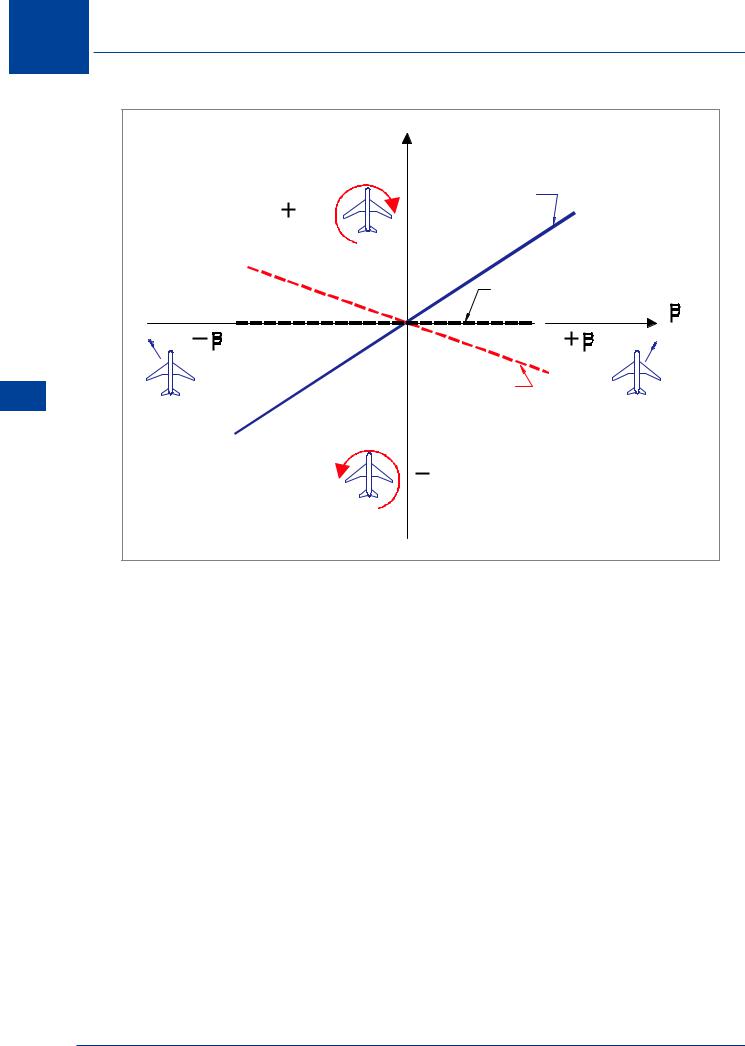
Static directional stability can be illustrated by a graph of yawing moment coefficient, Cn, versus sideslip angle, β, such as shown in Figure 10.55. When the aeroplane is subject to a positive sideslip angle, static directional stability will be evident if a positive yawing moment coefficient results. Thus, when the relative airflow comes from the right (+β ) a yawing moment to the right (+Cn) should be created which tends to “weathercock” the aeroplane and return the nose into the wind. Static directional stability will exist when the curve of Cn versus β has a positive slope, and the degree of stability will be a function of the slope of this curve. If the curve has zero slope, there is no tendency to return to equilibrium, and neutral static directional stability exists. When the curve of Cn versus β has a negative slope, the yawing moments developed by sideslip tend to diverge rather than restore, and static directional instability exists.
292
Stability and Control 10
|
|
NEUTRAL |
Cn |
STABLE |
UNSTABLE |
|
Figure 10.56
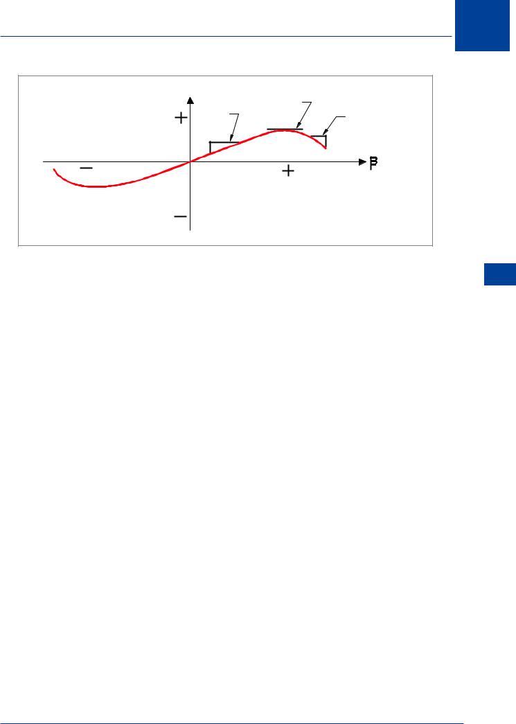
Figure 10.56 illustrates the fact that the instantaneous slope of the curve of Cn versus β will describe the static directional stability of the aeroplane.
•At small angles of sideslip, a strong positive slope depicts strong directional stability.
•Large angles of sideslip produce zero slope and neutral stability.
•At very high sideslip, the negative slope of the curve indicates directional instability.
This decay of directional stability with increased sideslip is not an unusual condition. However, directional instability should not occur at the angles of sideslip of ordinary flight conditions.
Static directional stability must be in evidence for all the critical conditions of flight. Generally, good directional stability is a fundamental quality directly affecting the pilots’ impression of an aeroplane.
Contribution of the Aeroplane Components.
Because the contribution of each component depends upon and is related to the others, it is necessary to study each separately.
Fuselage
The fuselage is destabilizing, Figure 10.57. It is an aerodynamic body and a condition of sideslip can be likened to an “angle of attack”, so that an aerodynamic side force is created. This side force acts through the fuselage aerodynamic centre (AC), which is close to the quarter-length point. If this aerodynamic centre is ahead of aircraft centre of gravity, as is usually the case, the effect is destabilizing.
Stability and Control 10
293
10 Stability and Control
Control and Stability 10
FUSELAGE (Plan View) |
|
FORCE |
|
AC |
FLIGHT PATH |
|
|
UNSTABLE |
|
YAWING |
|
MOMENT |
|
Figure 10.57
Dorsal andVentral Fins
To overcome the instability in the fuselage it is possible to incorporate into the overall design dorsal or ventral fins. A dorsal fin is a small aerofoil, of very low aspect ratio, mounted on top of the fuselage near the rear. A ventral fin is mounted below. Such fins are shown in Figure 10.58.
DORSAL FIN
FUSELAGE (Side View)
VENTRAL FIN
Figure 10.58
If the aircraft is yawed to the right, the dorsal and ventral fins will create a side force to the right. The line of action of this force is well aft of the aircraft CG, giving a yawing moment to the left (a stabilizing effect). However, at small angles of yaw they are ineffective.
294
Stability and Control 10
The side force created by dorsal and ventral fins at small sideslip angles will be very small because:
•the dorsal and ventral fins are at a low angle of attack,
•they have a small surface area, and
•their aspect ratio is very low, resulting in a small lift curve slope. Figure 10.59.
C F |
HIGH ASPECT |
RATIO |
 LOW ASPECT RATIO
(or sweepback)
Figure 10.59
When fitted with dorsal and ventral fins, a fuselage which is unstable in yaw will remain unstable at low sideslip angles. Dorsal and ventral fins become more effective at relatively high sideslip angles. Due to their low aspect ratio, they do not tend to stall at any sideslip angle which an aircraft is likely to experience in service.
The effectiveness of dorsal and ventral fins increases with increasing sideslip angle, so that the combination of a fuselage with dorsal or ventral fin is stable at large sideslip angles.
While dorsal and ventral fins contribute in exactly the same way to directional static stability, a dorsal fin contributes positively to lateral static stability, while a ventral fin is destabilizing in this mode, as will be demonstrated later. For this reason, the dorsal fin is much more common.
Stability and Control 10
DORSAL FIN
Figure 10.60
295
10 Stability and Control
Control and Stability 10
RELATIVE
AIRFLOW

 TAIL MOMENT

ARM
 CHANGE IN
FIN LIFT
Figure 10.61
Fin
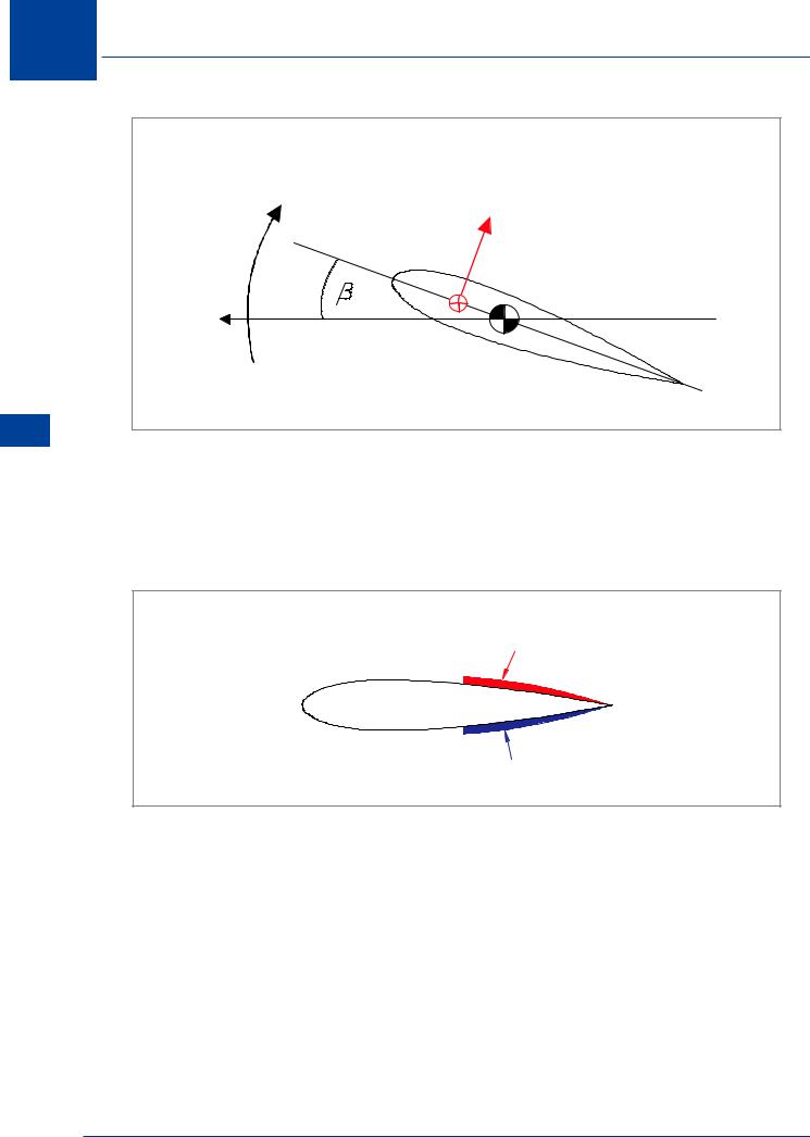
The fin (vertical stabilizer) is the major source of directional stability for the aeroplane. As shown in Figure 10.61, in a sideslip the fin will experience a change in angle of attack. The change in lift (side force) on the fin creates a yawing moment about the centre of gravity which tends to yaw the aeroplane into the relative airflow. The magnitude of the fin contribution to static directional stability depends on both the change in fin lift and the fin moment arm. Clearly, the fin moment arm is a powerful factor.
The contribution of the fin to directional stability depends on its ability to produce changes in lift, or side force, for a given change in sideslip angle. The contribution of the fin is a direct function of its area. The required directional stability may be obtained by increasing the fin area. However, increased surface area has the obvious disadvantage of increased parasite drag.
The lift curve slope of the fin determines how sensitive the surface is to change in angle of attack. While it is desirable to have a high lift curve slope for the fin, a high aspect ratio surface is not necessarily practical or desirable - bending, lower stalling angle (Figure 10.59), hangar roof clearance, etc. The stall angle of the surface must be sufficiently great to prevent stall and subsequent loss of effectiveness at expected sideslip angles. (Sweepback or low aspect ratio increases the stalling angle of attack of the fin).
The flow field in which the fin operates is affected by other components of the aeroplane as well as power effects. The dynamic pressure at the fin could depend on the slipstream of a propeller or the boundary layer of the fuselage. Also, the local flow direction at the fin is influenced by the wing wake, fuselage crossflow, induced flow of the horizontal tail or the direction of slipstream from a propeller. Each of these factors must be considered as possibly affecting the contribution of the fin to directional stability.
A high mounted tailplane (‘T’ - tail) makes the fin more effective by acting as an “end plate”.
296
Stability and Control 10
The side force on the fin may still be relatively small compared to that on the fuselage, which is destabilizing, but because its line of action is far aft of the CG, the yawing moment it creates is relatively large and gives overall stability to the fuselage-fin combination. The principle behind the effect of the fin as a stabilizer is just the same as in the case of the dorsal or ventral fin. However, because it is much larger and, in particular, has a much higher aspect ratio, it is effective at low angles of sideslip. It remains effective until the angle of sideslip is such that the fin angle of attack approaches its stalling angle, but above this value, the side force on the fin decreases with increasing sideslip angle, and the fin ceases to be effective as a stabilizer. It is at this point that the dorsal or ventral fin becomes important. Because it stalls at a very much higher angle of attack, it takes over the stabilizing role of the fin at large angles of sideslip.
Wing and Nacelles
The contribution of the wing to static directional stability is usually small:
•The contribution of a straight wing alone is usually negligible.
•Sweepback produces a stabilizing effect, which increases with increase in CL (i.e. at lower IAS).
•Engine nacelles on the wings produce a contribution that will depend on such factors as their size and position and the shape of the wing planform. On a straight wing, they usually produce a destabilizing effect.
A swept wing provides a stable contribution depending on the amount of sweepback, but the contribution is relatively weak when compared with other components. Consider a sideslipping swept wing, as illustrated in Figure 10.62.
V |
V |
NORMAL |
|
|
V 
NORMAL
Figure 10.62
Stability and Control 10
297
10 Stability and Control
Control and Stability 10
The inclination of the forward, right, wing to the relative airflow is greater than that of the rearward wing, so there is more lift and, hence, more induced drag, on the right side, (the influence of increased lift on the forward wing will be explained when lateral static stability is considered). The result of this discrepancy in drag on the two sides of the wing is a yawing moment to the right, which tends to eliminate the sideslip. This is a stabilizing effect, and may be important if the sweepback angle is quite large.
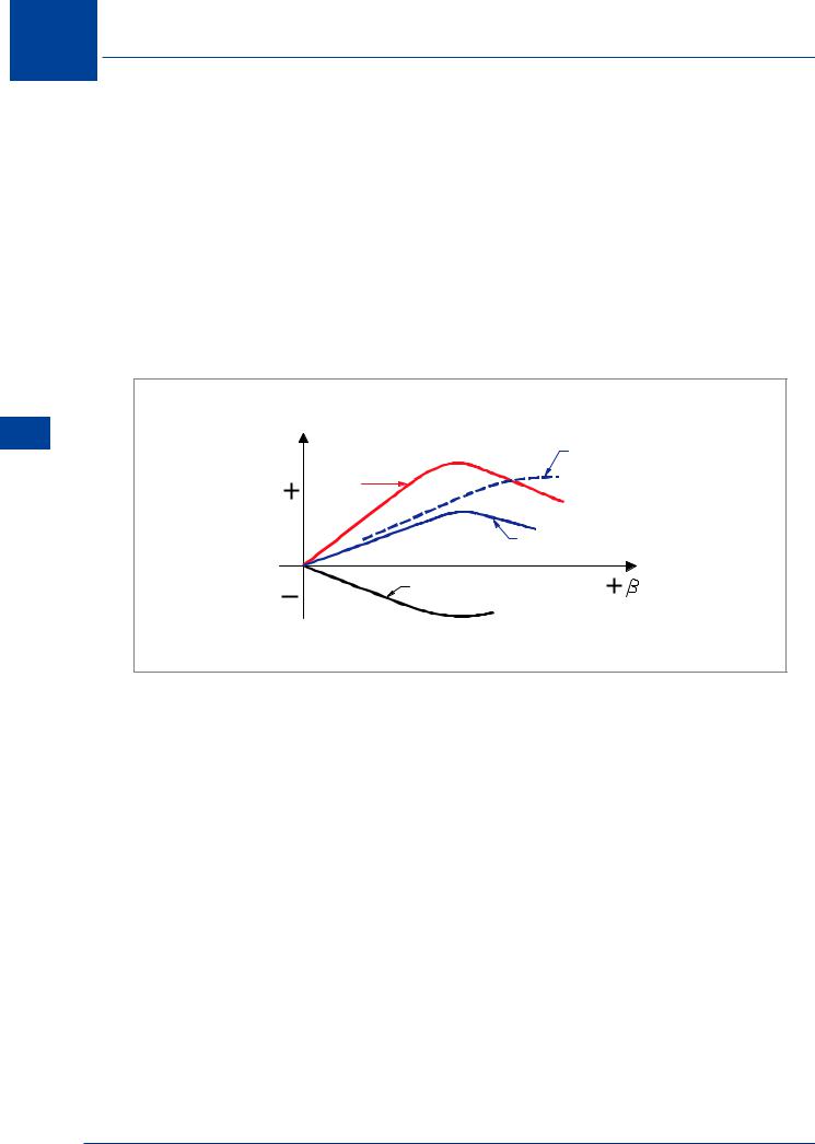
Figure 10.63 illustrates a typical build-up of the directional stability of an aeroplane by separating the contribution of the fuselage and fin. As shown by the graph of Cn versus β, the contribution of the fuselage is destabilizing, but the instability decreases at large sideslip angles. The contribution of the fin alone is highly stabilizing up to the point where the surface begins to stall. The contribution of the fin must be large enough so that the complete aeroplane (wing-fuselage-fin combination) exhibits the required degree of stability.
AEROPLANE WITH
|
STALL |
DORSAL FIN |
Cn |
ADDED |
|
FIN |
|
|
|
|
|
|
ALONE |
|
|
|
COMPLETE |
|
|
AEROPLANE |
|
FUSELAGE ALONE |
|
Figure 10.63
The dorsal fin has a powerful effect on preserving the directional stability at large angles of sideslip which would produce stall of the fin.
The addition of a dorsal fin to the aeroplane will reduce the decay of directional stability at high sideslip in two ways:
•The least obvious but most important effect is a large increase in the fuselage stability at large sideslip angles.
•In addition, the effective aspect ratio of the fin is reduced which increases the stall angle for the surface.
By this twofold effect, the addition of the dorsal fin is a very useful device. The decreased lift curve slope of a swept-back fin will also decrease the tendency for the fin to stall at high sideslip angles.
298
Stability and Control
Power Effect
The effects of power on static directional stability are similar to the power effects on static longitudinal stability. The direct effect is confined to the normal force at the propeller plane and, of course, is destabilizing when the propeller is located ahead of the CG. In addition, the air in the slipstream behind a propeller spirals around the fuselage, and this results in a sidewash at the fin (from the left with a clockwise rotating propeller). The indirect effects of power induced velocities and flow direction changes at the fin (spiral slipstream effect) are quite significant for the propeller driven aeroplane and can produce large directional trim changes. As in the longitudinal case, the indirect effects are negligible for the jet powered aeroplane.
The contribution of the direct and indirect power effects to static directional stability is greatest for the propeller powered aeroplane and usually slight for the jet powered aeroplane. In either case, the general effect of power is destabilizing and the greatest contribution will occur at high power and low dynamic pressure.
Critical Conditions
The most critical conditions of static directional stability are usually the combination of several separate effects. The combination which produces the most critical condition is much dependent upon the type of aeroplane. In addition, there exists a coupling of lateral and directional effects such that the required degree of static directional stability may be determined by some of these coupled conditions.
Centre of Gravity Position
Centre of gravity position has a relatively negligible effect on static directional stability. The usual range of CG position on any aeroplane is set by the limits of longitudinal stability and control. Within this limiting range of CG position, no significant changes take place in the contribution of the vertical tail, fuselage, nacelles, etc. Hence, static directional stability is essentially unaffected by the variation of CG position within the longitudinal limits.
LOW ANGLE |
OF ATTACK |
HIGH ANGLE |
OF ATTACK |
SIDESLIP ANGLE, 
Figure 10.64
10
Stability and Control 10
299
10
Control and Stability 10
Stability and Control
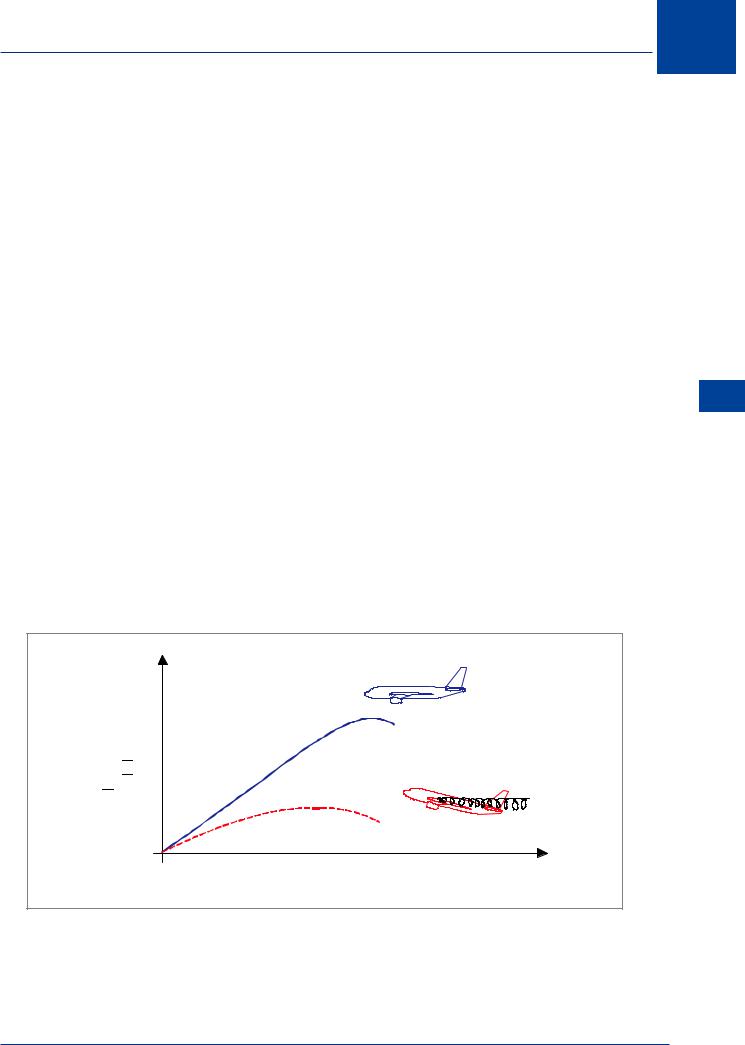
High Angle of Attack
When the aeroplane is at a high angle of attack a decrease in static directional stability can be anticipated. As shown by Figure 10.64, a high angle of attack reduces the stable slope of the curve of Cn versus β. The decrease in static directional stability is due in great part to the reduction in the contribution of the fin. At high angles of attack, the effectiveness of the fin is reduced because of increase in the fuselage boundary layer at the fin location. The decay of directional stability with angle of attack is most significant for an aeroplane with sweepback since this configuration requires a high angle of attack to achieve high lift coefficients.
Figure 10.65
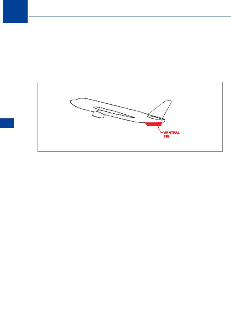
Ventral Fin
Ventral fins may be added as an additional contribution to directional stability, Figure 10.65. Landing clearance requirements may limit their size, require them to be retractable or require two smaller ventral fins to be fitted instead of one large one.
The most critical demands of static directional stability will occur from some combination of the following effects:
•high angle of sideslip
•high power at low airspeed
•high angle of attack
•high Mach number
The propeller powered aeroplane may have such considerable power effects that the critical conditions may occur at low speed, while the effect of high Mach numbers may produce the critical conditions for the typical transonic, jet powered aeroplane. In addition, the coupling of lateral and directional effects may require prescribed degrees of directional stability.
300