

- •Textbook Series
- •Contents
- •1 Overview and Definitions
- •Overview
- •General Definitions
- •Glossary
- •List of Symbols
- •Greek Symbols
- •Others
- •Self-assessment Questions
- •Answers
- •2 The Atmosphere
- •Introduction
- •The Physical Properties of Air
- •Static Pressure
- •Temperature
- •Air Density
- •International Standard Atmosphere (ISA)
- •Dynamic Pressure
- •Key Facts
- •Measuring Dynamic Pressure
- •Relationships between Airspeeds
- •Airspeed
- •Errors and Corrections
- •V Speeds
- •Summary
- •Questions
- •Answers
- •3 Basic Aerodynamic Theory
- •The Principle of Continuity
- •Bernoulli’s Theorem
- •Streamlines and the Streamtube
- •Summary
- •Questions
- •Answers
- •4 Subsonic Airflow
- •Aerofoil Terminology
- •Basics about Airflow
- •Two Dimensional Airflow
- •Summary
- •Questions
- •Answers
- •5 Lift
- •Aerodynamic Force Coefficient
- •The Basic Lift Equation
- •Review:
- •The Lift Curve
- •Interpretation of the Lift Curve
- •Density Altitude
- •Aerofoil Section Lift Characteristics
- •Introduction to Drag Characteristics
- •Lift/Drag Ratio
- •Effect of Aircraft Weight on Minimum Flight Speed
- •Condition of the Surface
- •Flight at High Lift Conditions
- •Three Dimensional Airflow
- •Wing Terminology
- •Wing Tip Vortices
- •Wake Turbulence: (Ref: AIC P 072/2010)
- •Ground Effect
- •Conclusion
- •Summary
- •Answers from page 77
- •Answers from page 78
- •Questions
- •Answers
- •6 Drag
- •Introduction
- •Parasite Drag
- •Induced Drag
- •Methods of Reducing Induced Drag
- •Effect of Lift on Parasite Drag
- •Aeroplane Total Drag
- •The Effect of Aircraft Gross Weight on Total Drag
- •The Effect of Altitude on Total Drag
- •The Effect of Configuration on Total Drag
- •Speed Stability
- •Power Required (Introduction)
- •Summary
- •Questions
- •Annex C
- •Answers
- •7 Stalling
- •Introduction
- •Cause of the Stall
- •The Lift Curve
- •Stall Recovery
- •Aircraft Behaviour Close to the Stall
- •Use of Flight Controls Close to the Stall
- •Stall Recognition
- •Stall Speed
- •Stall Warning
- •Artificial Stall Warning Devices
- •Basic Stall Requirements (EASA and FAR)
- •Wing Design Characteristics
- •The Effect of Aerofoil Section
- •The Effect of Wing Planform
- •Key Facts 1
- •Super Stall (Deep Stall)
- •Factors that Affect Stall Speed
- •1g Stall Speed
- •Effect of Weight Change on Stall Speed
- •Composition and Resolution of Forces
- •Using Trigonometry to Resolve Forces
- •Lift Increase in a Level Turn
- •Effect of Load Factor on Stall Speed
- •Effect of High Lift Devices on Stall Speed
- •Effect of CG Position on Stall Speed
- •Effect of Landing Gear on the Stall Speed
- •Effect of Engine Power on Stall Speed
- •Effect of Mach Number (Compressibility) on Stall Speed
- •Effect of Wing Contamination on Stall Speed
- •Warning to the Pilot of Icing-induced Stalls
- •Stabilizer Stall Due to Ice
- •Effect of Heavy Rain on Stall Speed
- •Stall and Recovery Characteristics of Canards
- •Spinning
- •Primary Causes of a Spin
- •Phases of a Spin
- •The Effect of Mass and Balance on Spins
- •Spin Recovery
- •Special Phenomena of Stall
- •High Speed Buffet (Shock Stall)
- •Answers to Questions on Page 173
- •Key Facts 2
- •Questions
- •Key Facts 1 (Completed)
- •Key Facts 2 (Completed)
- •Answers
- •8 High Lift Devices
- •Purpose of High Lift Devices
- •Take-off and Landing Speeds
- •Augmentation
- •Flaps
- •Trailing Edge Flaps
- •Plain Flap
- •Split Flap
- •Slotted and Multiple Slotted Flaps
- •The Fowler Flap
- •Comparison of Trailing Edge Flaps
- •and Stalling Angle
- •Drag
- •Lift / Drag Ratio
- •Pitching Moment
- •Centre of Pressure Movement
- •Change of Downwash
- •Overall Pitch Change
- •Aircraft Attitude with Flaps Lowered
- •Leading Edge High Lift Devices
- •Leading Edge Flaps
- •Effect of Leading Edge Flaps on Lift
- •Leading Edge Slots
- •Leading Edge Slat
- •Automatic Slots
- •Disadvantages of the Slot
- •Drag and Pitching Moment of Leading Edge Devices
- •Trailing Edge Plus Leading Edge Devices
- •Sequence of Operation
- •Asymmetry of High Lift Devices
- •Flap Load Relief System
- •Choice of Flap Setting for Take-off, Climb and Landing
- •Management of High Lift Devices
- •Flap Extension Prior to Landing
- •Questions
- •Annexes
- •Answers
- •9 Airframe Contamination
- •Introduction
- •Types of Contamination
- •Effect of Frost and Ice on the Aircraft
- •Effect on Instruments
- •Effect on Controls
- •Water Contamination
- •Airframe Aging
- •Questions
- •Answers
- •10 Stability and Control
- •Introduction
- •Static Stability
- •Aeroplane Reference Axes
- •Static Longitudinal Stability
- •Neutral Point
- •Static Margin
- •Trim and Controllability
- •Key Facts 1
- •Graphic Presentation of Static Longitudinal Stability
- •Contribution of the Component Surfaces
- •Power-off Stability
- •Effect of CG Position
- •Power Effects
- •High Lift Devices
- •Control Force Stability
- •Manoeuvre Stability
- •Stick Force Per ‘g’
- •Tailoring Control Forces
- •Longitudinal Control
- •Manoeuvring Control Requirement
- •Take-off Control Requirement
- •Landing Control Requirement
- •Dynamic Stability
- •Longitudinal Dynamic Stability
- •Long Period Oscillation (Phugoid)
- •Short Period Oscillation
- •Directional Stability and Control
- •Sideslip Angle
- •Static Directional Stability
- •Contribution of the Aeroplane Components.
- •Lateral Stability and Control
- •Static Lateral Stability
- •Contribution of the Aeroplane Components
- •Lateral Dynamic Effects
- •Spiral Divergence
- •Dutch Roll
- •Pilot Induced Oscillation (PIO)
- •High Mach Numbers
- •Mach Trim
- •Key Facts 2
- •Summary
- •Questions
- •Key Facts 1 (Completed)
- •Key Facts 2 (Completed)
- •Answers
- •11 Controls
- •Introduction
- •Hinge Moments
- •Control Balancing
- •Mass Balance
- •Longitudinal Control
- •Lateral Control
- •Speed Brakes
- •Directional Control
- •Secondary Effects of Controls
- •Trimming
- •Questions
- •Answers
- •12 Flight Mechanics
- •Introduction
- •Straight Horizontal Steady Flight
- •Tailplane and Elevator
- •Balance of Forces
- •Straight Steady Climb
- •Climb Angle
- •Effect of Weight, Altitude and Temperature.
- •Power-on Descent
- •Emergency Descent
- •Glide
- •Rate of Descent in the Glide
- •Turning
- •Flight with Asymmetric Thrust
- •Summary of Minimum Control Speeds
- •Questions
- •Answers
- •13 High Speed Flight
- •Introduction
- •Speed of Sound
- •Mach Number
- •Effect on Mach Number of Climbing at a Constant IAS
- •Variation of TAS with Altitude at a Constant Mach Number
- •Influence of Temperature on Mach Number at a Constant Flight Level and IAS
- •Subdivisions of Aerodynamic Flow
- •Propagation of Pressure Waves
- •Normal Shock Waves
- •Critical Mach Number
- •Pressure Distribution at Transonic Mach Numbers
- •Properties of a Normal Shock Wave
- •Oblique Shock Waves
- •Effects of Shock Wave Formation
- •Buffet
- •Factors Which Affect the Buffet Boundaries
- •The Buffet Margin
- •Use of the Buffet Onset Chart
- •Delaying or Reducing the Effects of Compressibility
- •Aerodynamic Heating
- •Mach Angle
- •Mach Cone
- •Area (Zone) of Influence
- •Bow Wave
- •Expansion Waves
- •Sonic Bang
- •Methods of Improving Control at Transonic Speeds
- •Questions
- •Answers
- •14 Limitations
- •Operating Limit Speeds
- •Loads and Safety Factors
- •Loads on the Structure
- •Load Factor
- •Boundary
- •Design Manoeuvring Speed, V
- •Effect of Altitude on V
- •Effect of Aircraft Weight on V
- •Design Cruising Speed V
- •Design Dive Speed V
- •Negative Load Factors
- •The Negative Stall
- •Manoeuvre Boundaries
- •Operational Speed Limits
- •Gust Loads
- •Effect of a Vertical Gust on the Load Factor
- •Effect of the Gust on Stalling
- •Operational Rough-air Speed (V
- •Landing Gear Speed Limitations
- •Flap Speed Limit
- •Aeroelasticity (Aeroelastic Coupling)
- •Flutter
- •Control Surface Flutter
- •Aileron Reversal
- •Questions
- •Answers
- •15 Windshear
- •Introduction (Ref: AIC 84/2008)
- •Microburst
- •Windshear Encounter during Approach
- •Effects of Windshear
- •“Typical” Recovery from Windshear
- •Windshear Reporting
- •Visual Clues
- •Conclusions
- •Questions
- •Answers
- •16 Propellers
- •Introduction
- •Definitions
- •Aerodynamic Forces on the Propeller
- •Thrust
- •Centrifugal Twisting Moment (CTM)
- •Propeller Efficiency
- •Variable Pitch Propellers
- •Power Absorption
- •Moments and Forces Generated by a Propeller
- •Effect of Atmospheric Conditions
- •Questions
- •Answers
- •17 Revision Questions
- •Questions
- •Answers
- •Explanations to Specimen Questions
- •Specimen Examination Paper
- •Answers to Specimen Exam Paper
- •Explanations to Specimen Exam Paper
- •18 Index
10 Stability and Control
Manoeuvre Stability
Control and Stability 10
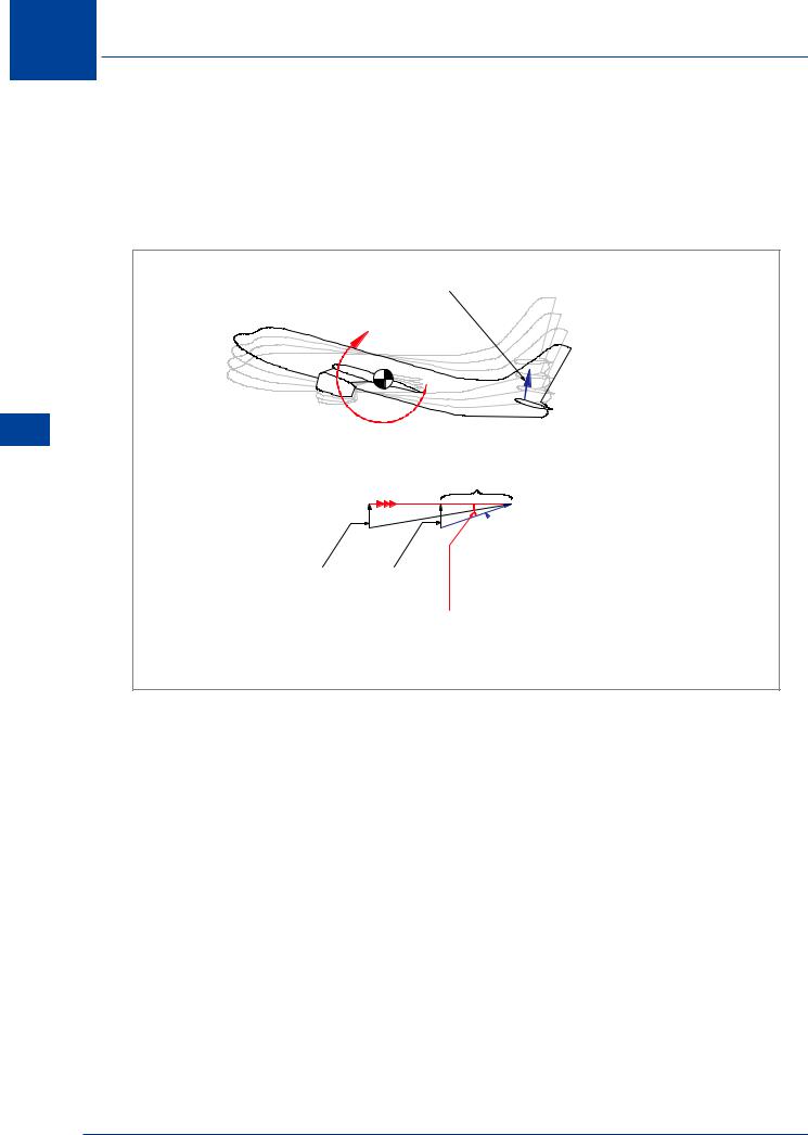
When the pilot pitches the aircraft, it rotates about the CG and the tailplane is subject to a pitching velocity, in this example, downwards. Due to the pitching velocity in manoeuvring flight, the longitudinal stability of the aeroplane is slightly greater than in steady flight conditions.
CHANGE IN TAIL LIFT
TAS
 RELATIVE AIRFLOW
FROM ANGULAR ROTATION
PITCHING VELOCITY
INCREASE IN TAIL ANGLE OF
ATTACK DUE TO PITCHING
VELOCITY
Figure 10.37 Aerodynamic damping
Figure 10.37 shows that the tailplane experiences an upwards component of airflow due to its downwards pitching velocity. The vector addition of this vertical component to the TAS provides an increase in effective angle of attack of the tail, which creates an increase in tail lift, opposing the nose-up pitch displacement.
Since the negative pitching moment opposes the nose-up pitch displacement but is due to the nose-up pitching motion, the effect is a damping in pitch (aerodynamic damping).
It can be seen that an increase in TAS, for a given pitching velocity, decreases the angle of attack due to pitching velocity.
274
Stability and Control 10
|
|
|
MANOEUVRE MARGIN |
|
|
|
L |
|
|
|
L |
x |
|
y |
|
|
|
||
|
|
|
|
Lt |
|
AC |
|
|
Lt |
|
|
|
|
AC |
FWD CG |
|
|
|
|
LIMIT |
|
|
NEUTRAL POINT |
|
HIGH |
|
|
10 |
|
|
|
|
||
STICK |
|
|
|
|
|
|
|
|
|
FORCE |
|
AFT CG |
Control |
|
|
|
LIMIT |
MANOEUVRE POINT |
|
|
|
LOW |
|
and |
|
|
STICK |
|
|
|
|
|
Stability |
|
|
|
FORCE |
|
|
|
|
|
|
|
|
|
|
Figure 10.38 Manoeuvre point |
|
The pitching moment from aerodynamic damping will give greater stability in manoeuvres than is apparent in steady flight. The CG position when the tail moment would be the same as the wing moment during manoeuvring is known as the manoeuvre point, and this “neutral point” will be further aft than for 1g flight, as shown in Figure 10.38.
In most cases the manoeuvre point will not be a critical item; if the aeroplane demonstrates static stability in 1g flight, it will definitely have stability in manoeuvring flight.
Stick Force Per ‘g’
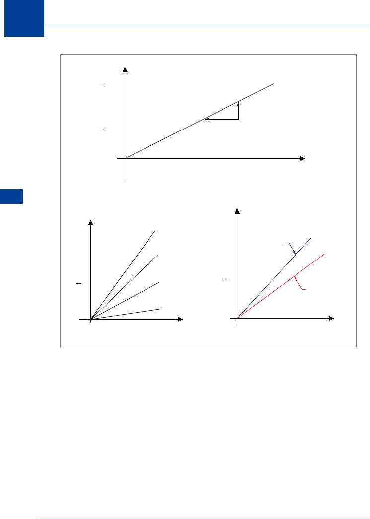
The most direct appreciation of the manoeuvring stability of an aeroplane is obtained from a plot of stick force versus load factor such as shown in Figure 10.39. The aeroplane with positive manoeuvring stability should demonstrate a steady increase in stick force with increase in load factor or “g”. The manoeuvring stick force gradient - or stick force per “g” - must be positive but should be of the proper magnitude. The stick force gradient must not be excessively high or the aeroplane will be difficult and tiring to manoeuvre. Also, the stick force gradient must not be too low or the aeroplane may be overstressed inadvertently when light control forces exist.
INCREASING ALTITUDE AT A CONSTANT IAS
DECREASES AERODYNAMIC DAMPING
275
10 Stability and Control
|
30 |
|
|
|
|
|
|
|
|
20 |
|
|
|
|
|
MANOEUVRING STICK |
|
|
|
|
|
|
|
|
FORCE GRADIENT |
|
|
10 |
|
|
|
|
|
|
|
|
1 |
2 |
3 |
4 |
5 |
6 |
7 |
8 |
|
|
|
|
LOAD FACTOR, (n) |
|
|||
|
|
|
|
|
or |
(g) |
|
|
10 |
|
|
|
|
|
|
|
|
Stability |
CG POSITION |
|
|
|
|
|
|
|
and |
% MAC |
|
|
|
|
|
|
|
|
|
|
|
|
|
|
LOW |
|
Control |
|
|
|
|
|
|
|
|
|
10 |
|
|
|
|
ALTITUDE |
||
|
|
|
|
|
|
|||
|
|
|
|
|
|
|
|
|
|
|
20 |
|
|
|
|
|
|
|
|
30 |
|
|
|
|
|
HIGH |
|
|
|
|
|
|
|
|
ALTITUDE |
|
|
40 |
|
|
|
|
|
|
|
LOAD FACTOR |
|
|
|
|
|
LOAD FACTOR |
|
|
|
|
|
Figure 10.39 |
|
|
||
When the aeroplane has high static stability, the manoeuvring stability will be high and a high stick force gradient will result, Figure 10.39. A possibility exists that the forward CG limit could be set to prevent an excessively high manoeuvring stick force gradient. As the CG moves aft, the stick force gradient decreases with decreasing manoeuvring stability and the lower limit of stick force gradient may be reached.
When asked to calculate ‘stick force per g’, remember that the aircraft is at 1g to start with. So 1g must be subtracted from the ‘g’ limit before dividing by the pull force.
The pitch damping of the aeroplane is related to air density. At high altitudes, the high TAS reduces the change in tail angle of attack for a given pitching velocity and reduces the pitch damping. Thus, a decrease in manoeuvring stick force stability can be expected with increased altitude.
276
Stability and Control 10
Tailoring Control Forces
Control forces should reflect the stability of the aeroplane but, at the same time, should be of a tolerable magnitude. A manual flying control system may employ an infinite variety of techniques to provide satisfactory control forces throughout the speed, CG and altitude range of the aircraft.
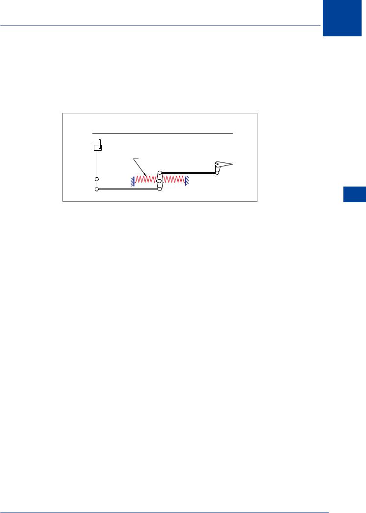
EFFECT OF STICK CENTRING SPRING
STICK CENTRING
SPRING
Figure 10.40
Stick Centring Spring
If a spring is added to the control system as shown in Figure 10.40, it will tend to centre the stick and provide a force increment depending on stick displacement.
When the control system has a fixed gearing between stick position and surface deflection, the centring spring will provide a contribution to stick force stability according to stick position.
The contribution to stick force stability will be largest at low flight speeds where relatively large control deflections are required. The contribution will be smallest at high airspeed because of the smaller control deflections required. Thus, the stick centring spring will increase the airspeed and manoeuvring stick force stability, but the contribution decreases at high airspeeds.
A variation of this device would be a spring stiffness which would be controlled to vary with dynamic pressure (Q - Feel). In that case, the contribution of the spring to stick force stability would not diminish with speed.
Down Spring
A down spring added to a control system is a means of increasing airspeed stick force stability without a change in aeroplane static stability.
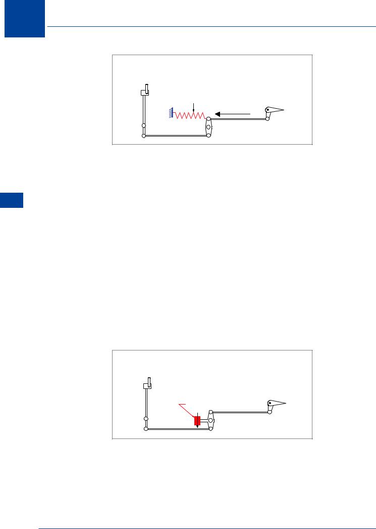
As shown in Figure 10.41, a down spring consists of a long pre-loaded spring attached to the control system which tends to rotate the elevators down (aircraft nose-down). The effect of the down spring is to contribute an increment of pull force independent of control deflection or airspeed.
Stability and Control 10
277
10 Stability and Control
Control and Stability 10
EFFECT OF DOWN SPRING
PRELOADED SPRING
Figure 10.41
When the down spring is added to the control system of an aeroplane and the aeroplane is re-trimmed for the original speed, the airspeed stick force gradient is increased and there is a stronger feel for airspeed. The down spring would provide a “synthetic” improvement to an aeroplane deficient in airspeed stick force stability. Since the force increment from the down spring is unaffected by stick position or normal acceleration, the manoeuvring stick force stability would be unchanged.
Bobweight
The bobweight is an effective device for improving stick force stability. As shown in Figure 10.42, the bobweight consists of an eccentric mass attached to the control system which, in unaccelerated flight, contributes an increment of pull force identical to the down spring. In fact, a bobweight added to the control system of an aeroplane produces an effect identical to the down spring. The bobweight will increase the airspeed stick force gradient and increase the feel for airspeed.
The bobweight also has an effect on the manoeuvring stick force gradient since the bobweight mass is subjected to the same acceleration as the aeroplane. Thus, the bobweight will provide an increment of stick force in direct proportion to the manoeuvring acceleration of the aeroplane (load factor applied). This will prevent the pilot applying too much ‘g’ during manoeuvres; the more you pull back, the more resistance the bobweight adds to the control system.
EFFECT OF BOBWEIGHT
BOBWEIGHT
Figure 10.42
278