

High Lift Devices |
|
8 |
|
||
|
|
|
WING |
TAILPLANE |
|
CP |
DOWNWASH |
|
|
|
|
|
|
8 |
|
INCREASED |
High Lift Devices |
|
|
|
|
DOWNWASH |
|
CP |
|
|
NOSE-DOWN |
NOSE-UP |
|
PITCHING MOMENT |
PITCHING MOMENT |
|
Figure 8.10
(a) |
(b) |
Overall Pitch Change
The resultant aircraft pitching moment will depend upon which of the two effects is dominant. The pitching moment will be influenced by the type of flap, the position of the wing and the relative position of the tailplane, and may be nose-up, nose-down or almost zero. For example, on flap extension, a tailplane mounted on top of the fin will be less influenced by the change of downwash, resulting in an increased aircraft nose-down pitching moment.
Aircraft Attitude with Flaps Lowered
When the aircraft is in steady flight the lift must be equal to the weight. If the flaps are lowered but the speed kept constant, lift will increase, and to maintain it at its original value, the angle of attack must be decreased. The aircraft will therefore fly in a more nose-down attitude if the flaps are down. On the approach to landing this is an advantage as it gives better visibility of the landing area.
215

8 High Lift Devices
Leading Edge High Lift Devices
There are two forms of leading edge high lift device commonly in use: the leading edge flap and the leading edge slot or slat.
Leading Edge Flaps
On high speed aerofoil sections the leading edge may have very little camber and have a small radius. This can give flow separation just aft of the leading edge at quite low angles of attack. This can be remedied by utilizing a leading edge flap, which increases the leading edge camber.
Devices Lift High 8
Figure 8.11 Krueger flap
Krueger Flap
The Krueger flap is part of the lower surface of the leading edge, which can be rotated about its forward edge as shown in Figure 8.11. To promote root stall on a swept wing, Krueger flaps are used on the inboard section because they are less efficient than the variable camber shown opposite.
216

High Lift Devices |
|
8 |
|
||
|
|
|
RETRACTED
EXTENDED
Figure 8.12 Variable camber leading edge flap
Variable Camber Leading Edge Flap
To improve efficiency by giving a better leading edge profile, the camber of a leading edge flap may be increased as it is deployed. Unlike trailing edge flaps, which can be selected to intermediate positions, leading edge flaps are usually either fully extended (deployed) or retracted (stowed).
Effect of Leading Edge Flaps on Lift
The main effect of the leading edge flap is to delay separation and so increase the stalling angle and the corresponding CLMAX. However, there will be some increase of lift at lower angles of attack due to the increased camber of the aerofoil section. Figure 8.13 shows the effect of these flaps on the lift curve.
WITH LEADING EDGE FLAP |
CL |
BASIC WING SECTION |
Figure 8.13
High Lift Devices 8
217
8 |
|
High Lift Devices |
|
||
|
|
|
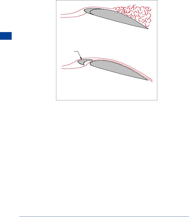
Leading Edge Slots
A leading edge slot is a gap from the lower surface to the upper surface of the leading edge, and it may be fixed, or created by moving part of the leading edge (the slat) forwards.
8 |
CLMAX WING |
(Given Adverse Pressure Gradient) |
Lift High |
SLAT |
|
Devices |
|
|
|
|
|
|
SLAT OPEN - Boundary Layer Re - energized |
|
|
(Same Adverse Pressure Gradient) |
|
Figure 8.14 Leading edge slat
Leading Edge Slat
A slat is a small auxiliary aerofoil attached to the leading edge of the wing, Figure 8.14. When deployed, the slat forms a slot which allows passage of air from the high pressure region below the wing to the low pressure region above it. Additional Kinetic Energy is added to the airflow through the slot by the slat forming a convergent duct.
When slats are deployed, the boundary layer is re-energized
If Kinetic Energy is added to the boundary layer, boundary layer separation will be delayed to a much higher angle of attack. At approximately 25°, the increased adverse pressure gradient will once again overwhelm the Kinetic Energy of the boundary layer and separation will occur.
If the slot is permanently open, i.e. a fixed slot, the extra drag at high speed is an unnecessary disadvantage, so most slats in commercial use are opened and closed by a control mechanism.
The slot can be closed for high speed flight and opened for low speeds, usually in conjunction with the trailing edge flaps and actuated by the same selector on the flight deck.
The graph at Figure 8.15 shows the comparative figures for a slatted and un-slatted wing of the same basic dimensions.
218
High Lift Devices |
|
8 |
|
||
|
|
|
2.0 |
|
|
|
WING PLUS |
|
|
|
SLATS |
|
C L |
|
|
|
|
1.5 |
|
CLMAX |
|
|
|
|
1.0
WING
0.5
5 |
10 |
15 |
20 |
25 |
30 |
Angle of Attack
Figure 8.15
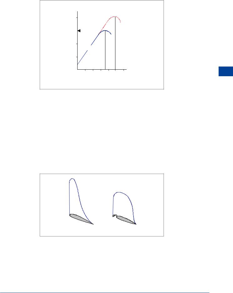
The effect of the slat is to prolong the lift curve by delaying boundary layer separation until a higher angle of attack. When operating at high angles of attack, the slat itself is generating a high lift coefficient because of its marked camber. The action of the slat is to flatten the marked peak of the low pressure envelope at high angles of attack and to change it to one with a more gradual pressure gradient. The flattening of the lift distribution envelope means that the boundary layer does not undergo the sudden thickening that occurred through having to negotiate the very steep adverse pressure gradient that existed immediately behind the former ‘suction’ peak, and so it retains much of its Kinetic Energy, thus enabling it to penetrate almost the full chord of the wing before separating. Figure 8.16 shows the alleviating effect of the slat on the low pressure peak and that, although flatter, the area of the low pressure region, which is proportional to its strength, is unchanged or even increased. The ‘suction’ peak does not move forward, so the effect of the slot on pitching moment is insignificant.
High Lift Devices 8
No Slat |
With Slat |
Figure 8.16
219