

High Lift Devices |
|
8 |
|
||
|
|
|
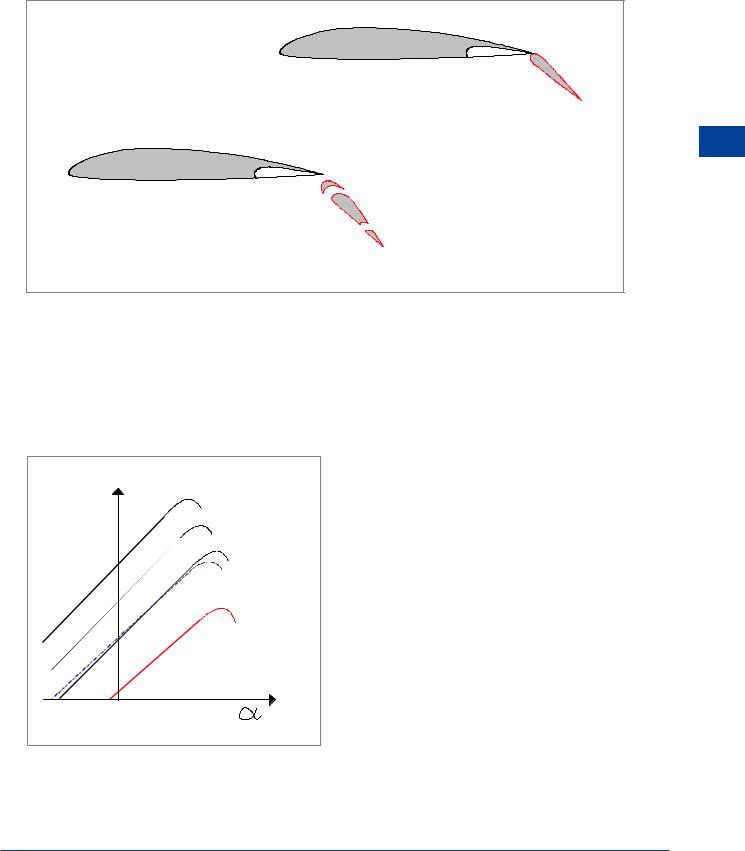
The Fowler Flap
The Fowler flap, Figure 8.4, moves rearwards and then down, initially giving an increase in wing area and then an increase in camber. The Fowler flap may be slotted.
|
|
|
Fowler |
Flap |
|
|
|
|
8 |
|
|
|
|
High Lift Devices |
Triple |
Slotted |
Fowler |
Flap |
|
|
|
|
Figure 8.4 |
|
Because of the combined effects of increased area and camber, the Fowler flap gives the greatest increase in lift of the flaps considered and also gives the least drag because of the slot and the reduction of thickness : chord ratio. However, the change of pitching moment is greater because of the rearward extension of the chord.
Comparison of Trailing Edge Flaps
|
FOWLER FLAP |
CL |
SLOTTED FLAP |
|
|
|
SPLIT FLAP |
|
PLAIN FLAP |
|
BASIC SECTION |
Figure 8.5 shows a comparison of the lift curves for the flaps considered above, for the same angle of flap deflection. It should be noted, however, that the different types of flap do not all give their greatest increase in lift at the same flap angle.
Figure 8.5
211
8 |
|
High Lift Devices |
|
||
|
|
|
Figure 8.6 shows the variation of the lift increment with flap angle and the variation of drag increment with flap angle. It can be seen that the increment in lift is decreasing and the increment in drag is increasing as flaps are deployed. It is important to note that any amount of flap increases drag.
|
|
CL |
|
|
CD |
|
|
5º |
TO |
10º |
|
|
|
|
|
8 |
|
|
|
|
|
|
|
High |
0º |
TO 5º |
|
5º |
TO 10º |
|
|
Lift |
|
0º |
5º |
10º |
|
|
|
Devices |
|
TO 5º |
|
|
|||
|
|
|
|
0º |
|
|
|
|
|
|
|
|
0º |
5º |
10º |
|
|
|
|
FLAP ANGLE |
|
|
FLAP ANGLE |
Figure 8.6
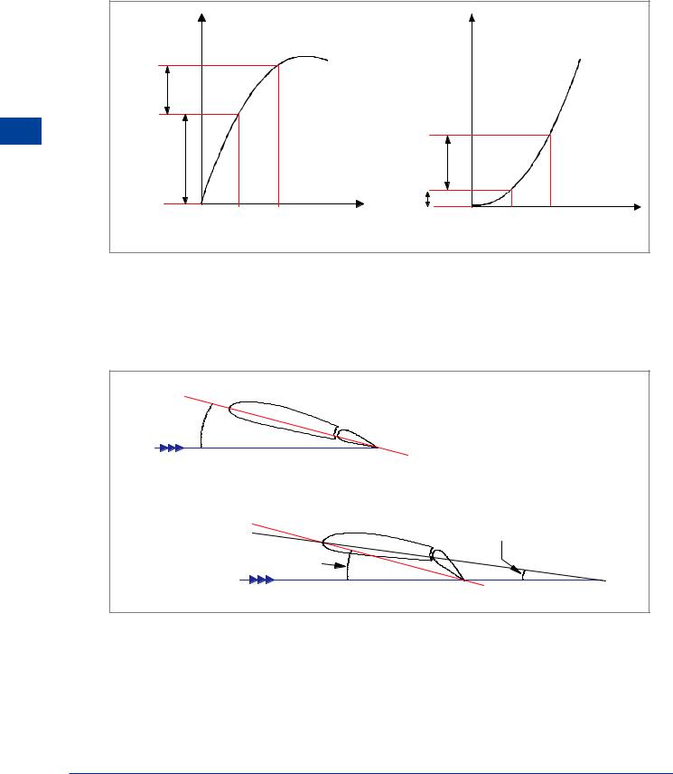
CLMAX and Stalling Angle
It can be seen from Figure 8.5 that with the flap lowered CLMAX is increased, but the stalling angle is reduced. This is because lowering the flap increases the effective angle of attack.
REDUCED ANGLE OF ATTACK |
OF BASIC SECTION |
EFFECTIVE |
ANGLE OF ATTACK |
Figure 8.7
It is conventional to plot the CL ~ α curve using the angle of attack for the basic section. Consequently, as shown in Figure 8.7, at the stalling angle of attack for the section with flap lowered, the basic wing section is at a reduced angle.
212
High Lift Devices |
|
8 |
|
||
|
|
|
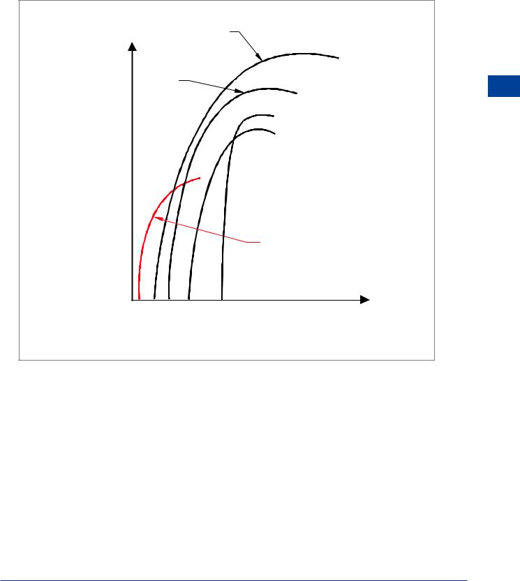
Drag
Figure 8.8 shows a comparison of the drag polar curves for the various types of flap. It can be seen that for a given flap deflection the drag produced by the different types of flap varies considerably, the split flap giving the highest drag and the Fowler flap the least.
|
|
FOWLER |
|
CL |
SLOTTED |
|
8 |
|
|
SPLIT |
DevicesLift |
|
|
|
|
|
|
PLAIN |
High |
|
|
|
|
|
|
BASIC SECTION |
|
|
|
CD |
|
Figure 8.8
During take-off, drag reduces the acceleration, and so the flap should give as little drag as possible. For landing, however, drag adds to the braking force and so the flap drag is beneficial. The addition of drag during approach also improves speed stability.
As in the case of the lift increments, the drag increments with increasing flap angle are not constant: the increments in drag get larger as the flap angle increases.
213
8 High Lift Devices
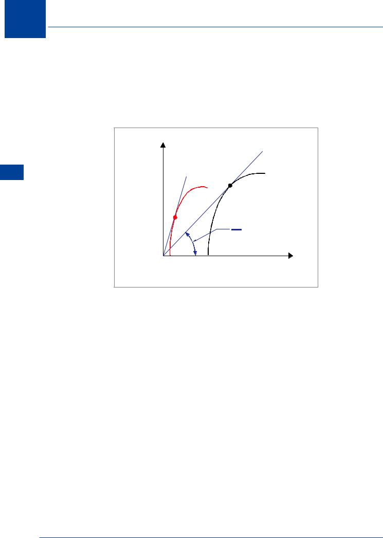
Lift / Drag Ratio
Lowering flap increases both the lift and the drag, but not in the same proportion. Although the lift is the larger force, the proportional increase in the drag is greater, and so the maximum obtainable lift / drag ratio decreases. The maximum lift / drag ratio occurs where the tangent from the origin of the drag polar touches the curve, and the gradient of the tangent line is a measure of the maximum lift / drag ratio (Figure 8.9).
Devices Lift High 8
CL
LD RATIO
CD
Figure 8.9 L/D ratio
The lift / drag ratio is a measure of aerodynamic efficiency and affects the aircraft’s performance in areas such as range, climb angle and glide angle. With flaps lowered, range will be decreased, climb angle reduced and glide angle increased.
Pitching Moment
Flap movement, up or down, will usually cause a change of pitching moment. This is due to Centre of Pressure (CP) movement and downwash at the tailplane.
Centre of Pressure Movement
Moving a trailing edge flap will modify the pressure distribution over the whole chord of the aerofoil, but the greatest changes will occur in the region of the flap. When flap is lowered, the Centre of Pressure will move rearwards giving a nose-down pitching moment, Figure 8.10a. In the case of a Fowler flap, rearward movement of the flap will also cause the CP to move aft, resulting in an even greater increase in the nose-down pitching moment.
Change of Downwash
Tailplane effective angle of attack is determined by the downwash from the wing. If the flaps are lowered, the downwash will increase and the tailplane angle of attack will decrease, causing a nose-up pitching moment, Figure 8.10b.
214