
- •Textbook Series
- •Contents
- •1 Overview and Definitions
- •Overview
- •General Definitions
- •Glossary
- •List of Symbols
- •Greek Symbols
- •Others
- •Self-assessment Questions
- •Answers
- •2 The Atmosphere
- •Introduction
- •The Physical Properties of Air
- •Static Pressure
- •Temperature
- •Air Density
- •International Standard Atmosphere (ISA)
- •Dynamic Pressure
- •Key Facts
- •Measuring Dynamic Pressure
- •Relationships between Airspeeds
- •Airspeed
- •Errors and Corrections
- •V Speeds
- •Summary
- •Questions
- •Answers
- •3 Basic Aerodynamic Theory
- •The Principle of Continuity
- •Bernoulli’s Theorem
- •Streamlines and the Streamtube
- •Summary
- •Questions
- •Answers
- •4 Subsonic Airflow
- •Aerofoil Terminology
- •Basics about Airflow
- •Two Dimensional Airflow
- •Summary
- •Questions
- •Answers
- •5 Lift
- •Aerodynamic Force Coefficient
- •The Basic Lift Equation
- •Review:
- •The Lift Curve
- •Interpretation of the Lift Curve
- •Density Altitude
- •Aerofoil Section Lift Characteristics
- •Introduction to Drag Characteristics
- •Lift/Drag Ratio
- •Effect of Aircraft Weight on Minimum Flight Speed
- •Condition of the Surface
- •Flight at High Lift Conditions
- •Three Dimensional Airflow
- •Wing Terminology
- •Wing Tip Vortices
- •Wake Turbulence: (Ref: AIC P 072/2010)
- •Ground Effect
- •Conclusion
- •Summary
- •Answers from page 77
- •Answers from page 78
- •Questions
- •Answers
- •6 Drag
- •Introduction
- •Parasite Drag
- •Induced Drag
- •Methods of Reducing Induced Drag
- •Effect of Lift on Parasite Drag
- •Aeroplane Total Drag
- •The Effect of Aircraft Gross Weight on Total Drag
- •The Effect of Altitude on Total Drag
- •The Effect of Configuration on Total Drag
- •Speed Stability
- •Power Required (Introduction)
- •Summary
- •Questions
- •Annex C
- •Answers
- •7 Stalling
- •Introduction
- •Cause of the Stall
- •The Lift Curve
- •Stall Recovery
- •Aircraft Behaviour Close to the Stall
- •Use of Flight Controls Close to the Stall
- •Stall Recognition
- •Stall Speed
- •Stall Warning
- •Artificial Stall Warning Devices
- •Basic Stall Requirements (EASA and FAR)
- •Wing Design Characteristics
- •The Effect of Aerofoil Section
- •The Effect of Wing Planform
- •Key Facts 1
- •Super Stall (Deep Stall)
- •Factors that Affect Stall Speed
- •1g Stall Speed
- •Effect of Weight Change on Stall Speed
- •Composition and Resolution of Forces
- •Using Trigonometry to Resolve Forces
- •Lift Increase in a Level Turn
- •Effect of Load Factor on Stall Speed
- •Effect of High Lift Devices on Stall Speed
- •Effect of CG Position on Stall Speed
- •Effect of Landing Gear on the Stall Speed
- •Effect of Engine Power on Stall Speed
- •Effect of Mach Number (Compressibility) on Stall Speed
- •Effect of Wing Contamination on Stall Speed
- •Warning to the Pilot of Icing-induced Stalls
- •Stabilizer Stall Due to Ice
- •Effect of Heavy Rain on Stall Speed
- •Stall and Recovery Characteristics of Canards
- •Spinning
- •Primary Causes of a Spin
- •Phases of a Spin
- •The Effect of Mass and Balance on Spins
- •Spin Recovery
- •Special Phenomena of Stall
- •High Speed Buffet (Shock Stall)
- •Answers to Questions on Page 173
- •Key Facts 2
- •Questions
- •Key Facts 1 (Completed)
- •Key Facts 2 (Completed)
- •Answers
- •8 High Lift Devices
- •Purpose of High Lift Devices
- •Take-off and Landing Speeds
- •Augmentation
- •Flaps
- •Trailing Edge Flaps
- •Plain Flap
- •Split Flap
- •Slotted and Multiple Slotted Flaps
- •The Fowler Flap
- •Comparison of Trailing Edge Flaps
- •and Stalling Angle
- •Drag
- •Lift / Drag Ratio
- •Pitching Moment
- •Centre of Pressure Movement
- •Change of Downwash
- •Overall Pitch Change
- •Aircraft Attitude with Flaps Lowered
- •Leading Edge High Lift Devices
- •Leading Edge Flaps
- •Effect of Leading Edge Flaps on Lift
- •Leading Edge Slots
- •Leading Edge Slat
- •Automatic Slots
- •Disadvantages of the Slot
- •Drag and Pitching Moment of Leading Edge Devices
- •Trailing Edge Plus Leading Edge Devices
- •Sequence of Operation
- •Asymmetry of High Lift Devices
- •Flap Load Relief System
- •Choice of Flap Setting for Take-off, Climb and Landing
- •Management of High Lift Devices
- •Flap Extension Prior to Landing
- •Questions
- •Annexes
- •Answers
- •9 Airframe Contamination
- •Introduction
- •Types of Contamination
- •Effect of Frost and Ice on the Aircraft
- •Effect on Instruments
- •Effect on Controls
- •Water Contamination
- •Airframe Aging
- •Questions
- •Answers
- •10 Stability and Control
- •Introduction
- •Static Stability
- •Aeroplane Reference Axes
- •Static Longitudinal Stability
- •Neutral Point
- •Static Margin
- •Trim and Controllability
- •Key Facts 1
- •Graphic Presentation of Static Longitudinal Stability
- •Contribution of the Component Surfaces
- •Power-off Stability
- •Effect of CG Position
- •Power Effects
- •High Lift Devices
- •Control Force Stability
- •Manoeuvre Stability
- •Stick Force Per ‘g’
- •Tailoring Control Forces
- •Longitudinal Control
- •Manoeuvring Control Requirement
- •Take-off Control Requirement
- •Landing Control Requirement
- •Dynamic Stability
- •Longitudinal Dynamic Stability
- •Long Period Oscillation (Phugoid)
- •Short Period Oscillation
- •Directional Stability and Control
- •Sideslip Angle
- •Static Directional Stability
- •Contribution of the Aeroplane Components.
- •Lateral Stability and Control
- •Static Lateral Stability
- •Contribution of the Aeroplane Components
- •Lateral Dynamic Effects
- •Spiral Divergence
- •Dutch Roll
- •Pilot Induced Oscillation (PIO)
- •High Mach Numbers
- •Mach Trim
- •Key Facts 2
- •Summary
- •Questions
- •Key Facts 1 (Completed)
- •Key Facts 2 (Completed)
- •Answers
- •11 Controls
- •Introduction
- •Hinge Moments
- •Control Balancing
- •Mass Balance
- •Longitudinal Control
- •Lateral Control
- •Speed Brakes
- •Directional Control
- •Secondary Effects of Controls
- •Trimming
- •Questions
- •Answers
- •12 Flight Mechanics
- •Introduction
- •Straight Horizontal Steady Flight
- •Tailplane and Elevator
- •Balance of Forces
- •Straight Steady Climb
- •Climb Angle
- •Effect of Weight, Altitude and Temperature.
- •Power-on Descent
- •Emergency Descent
- •Glide
- •Rate of Descent in the Glide
- •Turning
- •Flight with Asymmetric Thrust
- •Summary of Minimum Control Speeds
- •Questions
- •Answers
- •13 High Speed Flight
- •Introduction
- •Speed of Sound
- •Mach Number
- •Effect on Mach Number of Climbing at a Constant IAS
- •Variation of TAS with Altitude at a Constant Mach Number
- •Influence of Temperature on Mach Number at a Constant Flight Level and IAS
- •Subdivisions of Aerodynamic Flow
- •Propagation of Pressure Waves
- •Normal Shock Waves
- •Critical Mach Number
- •Pressure Distribution at Transonic Mach Numbers
- •Properties of a Normal Shock Wave
- •Oblique Shock Waves
- •Effects of Shock Wave Formation
- •Buffet
- •Factors Which Affect the Buffet Boundaries
- •The Buffet Margin
- •Use of the Buffet Onset Chart
- •Delaying or Reducing the Effects of Compressibility
- •Aerodynamic Heating
- •Mach Angle
- •Mach Cone
- •Area (Zone) of Influence
- •Bow Wave
- •Expansion Waves
- •Sonic Bang
- •Methods of Improving Control at Transonic Speeds
- •Questions
- •Answers
- •14 Limitations
- •Operating Limit Speeds
- •Loads and Safety Factors
- •Loads on the Structure
- •Load Factor
- •Boundary
- •Design Manoeuvring Speed, V
- •Effect of Altitude on V
- •Effect of Aircraft Weight on V
- •Design Cruising Speed V
- •Design Dive Speed V
- •Negative Load Factors
- •The Negative Stall
- •Manoeuvre Boundaries
- •Operational Speed Limits
- •Gust Loads
- •Effect of a Vertical Gust on the Load Factor
- •Effect of the Gust on Stalling
- •Operational Rough-air Speed (V
- •Landing Gear Speed Limitations
- •Flap Speed Limit
- •Aeroelasticity (Aeroelastic Coupling)
- •Flutter
- •Control Surface Flutter
- •Aileron Reversal
- •Questions
- •Answers
- •15 Windshear
- •Introduction (Ref: AIC 84/2008)
- •Microburst
- •Windshear Encounter during Approach
- •Effects of Windshear
- •“Typical” Recovery from Windshear
- •Windshear Reporting
- •Visual Clues
- •Conclusions
- •Questions
- •Answers
- •16 Propellers
- •Introduction
- •Definitions
- •Aerodynamic Forces on the Propeller
- •Thrust
- •Centrifugal Twisting Moment (CTM)
- •Propeller Efficiency
- •Variable Pitch Propellers
- •Power Absorption
- •Moments and Forces Generated by a Propeller
- •Effect of Atmospheric Conditions
- •Questions
- •Answers
- •17 Revision Questions
- •Questions
- •Answers
- •Explanations to Specimen Questions
- •Specimen Examination Paper
- •Answers to Specimen Exam Paper
- •Explanations to Specimen Exam Paper
- •18 Index

7 Stalling
Super Stall (Deep Stall)
A swept-back wing tends to stall first near the tips. Since the tips are situated well aft of the CG, the loss of lift at the tips causes the pitch attitude to increase rapidly and further increase the angle of attack. Figure 7.19.
7
PITCH - UP
Stalling
TIP STALL
Figure 7.19 Pitch-up
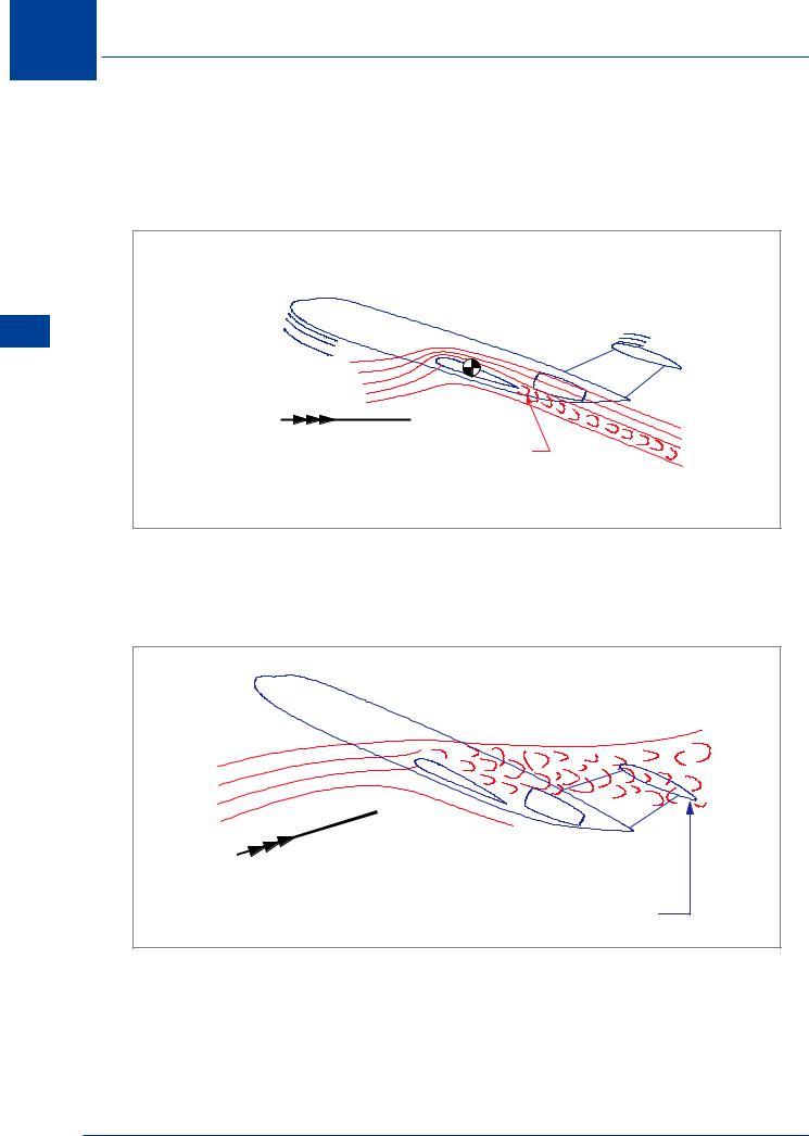
This “automatic” increase in angle of attack, caused by pitch-up, stalls more of the wing. Drag will increase rapidly, lift will reduce and the aeroplane will start to sink at a constant, nose high, pitch attitude. This results in a rapid additional increase in angle of attack, Figure 7.20.
DOWNWARD INCLINED FLIGHT PATH |
TAILPLANE IMMERSED |
IN SEPARATED AIRFLOW |
FROM STALLED WING |
Figure 7.20 Super stall
Separated airflow from the stalled wing will immerse a high-set tailplane in low energy turbulent air, Figure 7.20. Elevator effectiveness is greatly reduced making it impossible for the pilot to decrease the angle of attack. The aeroplane will become stabilized in what is known as the “super stall” or “deep stall” condition.
166

Stalling 7
Clearly, the combination of a swept-back wing and a high mounted tailplane (‘T’ - Tail) are the factors involved in the “super or deep stall”. Of the two:
THE SWEPT-BACK WING IS THE MAJOR CONTRIBUTORY FACTOR.
It has been shown that the tendency for a swept-back wing to pitch-up can be reduced by design modifications (wing fences, vortilons and saw tooth leading edges) which minimize the root-to-tip spanwise flow of the boundary layer. These devices delay tip stall. Vortex generators are also frequently used on a swept wing to delay tip stall and improve the stall characteristics.
The wing root can also be encouraged to stall first. This can be done by modifying the aerofoil section at the root, fitting stall strips and by fitting less efficient leading edge flaps (Kruger flaps) to the inboard section of the wing.
Aircraft such as the DC-9, MD-80, Boeing 727, Fokker 28 and others, have swept-back wings and high mounted tailplanes (‘T’ - Tail). They also have rear, fuselage mounted engines. The only contribution rear mounted engines make is that they are the reason the designer placed the tailplane on top of the fin in the first place. In and of itself, mounting the engines on the rear fuselage does not contribute to super stall.
Super Stall Prevention - Stick Pusher
An aircraft design which exhibits super stall characteristics must be fitted with a device to prevent it from ever stalling. This device is a stick pusher. Once such an aircraft begins to stall it is too late; the progression to super stall is too fast for a human to respond, and the aircraft cannot then be un-stalled.
A stick pusher is a device, attached to the elevator control system, which physically pushes the control column forward, reducing the angle of attack before super stall can occur.
The force of the push is typically about 80 lb. This is regarded as being high enough to be effective but not too high to hold in a runaway situation. Provision is made to “dump” the stick pusher system in the event of a malfunction. Once dumped, the pusher cannot normally be reset in flight.
Once actuated, the stick pusher will automatically disengage once the angle of attack reduces below a suitable value.
Stalling 7
167

7 Stalling
Stalling 7
Factors that Affect Stall Speed
Page 148 details the CAS at which an aircraft stalls (VSR). We know that stalling is caused by exceeding the critical angle of attack. Stalling has nothing to do with the speed of the aircraft; the critical angle of attack can be exceeded at any aircraft speed. However, it has been shown that if an aircraft is flown in straight and level flight and speed reduced at a rate not exceeding 1 knot per second, the CAS at which it stalls can be identified. It is upon this reference stall speed (VSR) that the recommended take-off, manoeuvre, approach and landing speeds are based, to give an adequate margin from the stall during normal operations (1.05VSR, 1.1VSR, 1.2VSR, 1.3VSR etc).
Factors which can affect VSR are:
•Changes in weight.
•Manoeuvring the aircraft (increasing the load factor).
•Configuration changes (changes in CLMAX and pitching moment).
•CG position.
•Engine thrust and propeller slipstream.
•Mach number.
•Wing contamination.
•Heavy rain.
1g Stall Speed
In straight and level flight the weight of the aircraft is balanced by the lift.
Load Factor (n) or ‘g’ = |
Lift |
Weight |
While (n) is the correct symbol for load factor, the relationship between lift and weight has for years been popularly known as ‘g’. (1g corresponds to the force acting on us in every day life). If more lift is generated than weight, the load factor or ‘g’ will be greater than one; the force acting on the aircraft and everything in it, including the pilot, will be greater.
If Lift = Weight, the load factor will be one and from the lift formula:
L = ½ ρ V2 CL S
it can be seen that lift will change whenever any of the other factors in the formula change. We consider density (ρ) and wing area (S) constant for this example. If the engine is throttled back, drag will reduce speed (V) and, from the formula, it can be seen that lift would decrease. To keep lift constant and maintain 1g flight at a reduced speed, CL must be increased by increasing the angle of attack.
168

Stalling 7
Any further reduction in speed would need a further increase in angle of attack, each succeeding lower CAS corresponding to a greater angle of attack. Eventually, at a certain CAS, the wing reaches its stalling angle (CLMAX), beyond which any further increase in angle of attack, in an attempt to maintain lift, will precipitate a stall. We can transpose the lift formula to show this relationship:-
|
|
√ |
|
|
|
|
|
Density altitude does not |
|
VS1g |
= |
|
|
|
|
L |
|
|
|
|
|
|
|
|
|
affect indicated stall speed |
|||
|
|
½ |
ρ |
CLMAX S |
|
|
|||
|
|
|
|
|
|
|
Effect of Weight Change on Stall Speed
At CLMAX for 1g flight, a change in weight requires a change in lift and it can be seen from the VS1g formula that, for instance, an increase in weight (lift) will increase VS1g
The relationship between basic stalling speeds at two different weights can be obtained from the following formula:
|
|
|
|
VS1g new = VS1g old √ |
new weight |
|
|
old weight |
|
The angle of attack at which stall occurs will NOT be affected by the weight. (Provided that the appropriate value of CLMAX is not affected by speed - as it will be at speeds greater than M0.4, see page 177). To maintain a given angle of attack in level flight, it is necessary to change the dynamic pressure (CAS) if the weight is changed.
As an example: at a weight of 588 600 N an aircraft stalls at 150 kt CAS. What is the VS1g stall speed at a weight of 470 880 N?
|
|
|
|
VS1g new = 150 √ |
470880 |
Weight does not |
|
588600 |
affect stall angle |
=134 knots CAS
It should be noted that a 20% reduction in weight has resulted in an approximate 10% reduction in stall speed. (As a “rule of thumb”, this relationship can be used to save calculator batteries, and time in the exam!). The change in stall speed due to an increase in weight can be calculated in the same way.
Stalling 7
169