

6 Drag
Drag 6
The Effect of Aircraft Gross Weight on Total Drag
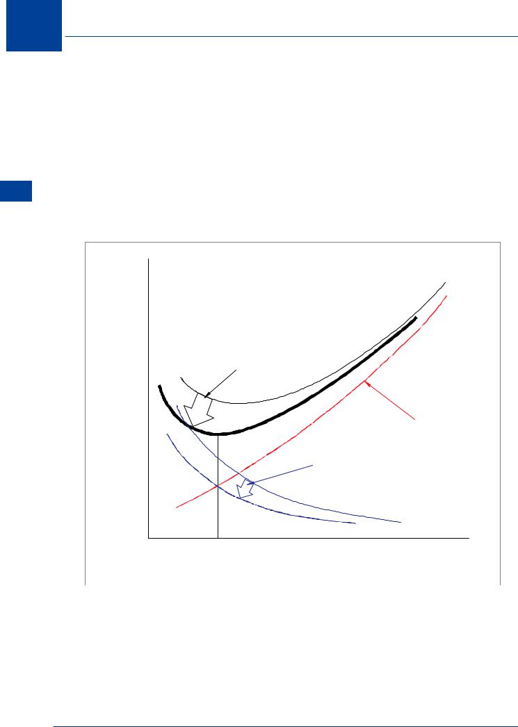
The effect of variation in aircraft gross weight on total drag can be seen from Figure 6.18. As fuel is consumed, gross weight will decrease. As the aircraft weight decreases, less lift is required (lower CL) which will reduce induced drag. Total drag will be less and VMD will occur at a lower IAS.
If an aircraft is operated at a higher gross weight, more lift will be required. If more lift is generated, induced drag will be higher, total drag will be greater and VMD will occur at a higher IAS. If an aircraft is manoeuvred so that the load factor is increased, the result will be similar to that caused by an increase in gross weight, i.e. induced drag will increase.
DRAG |
|
Decreased |
|
TOTAL DRAG |
|
at lower weight |
|
|
Parasite Drag |
Less |
|
Induced |
Drag |
at lower weight |
|
Decreased VMD |
IAS |
because of lower weight |
|
|
|
|
Figure 6.18 |
126
Drag 6
The Effect of Altitude on Total Drag
Aircraft usually operate within limits of Indicated Airspeed (IAS), so it is relevant to consider the variation of drag with IAS. If an aircraft is flown at a constant IAS, dynamic pressure will be constant. As density decreases with increasing altitude, TAS must be increased to maintain the constant IAS (Q = ½ ρ V2 ). If the aircraft is flown at a constant IAS, drag will not vary with altitude.
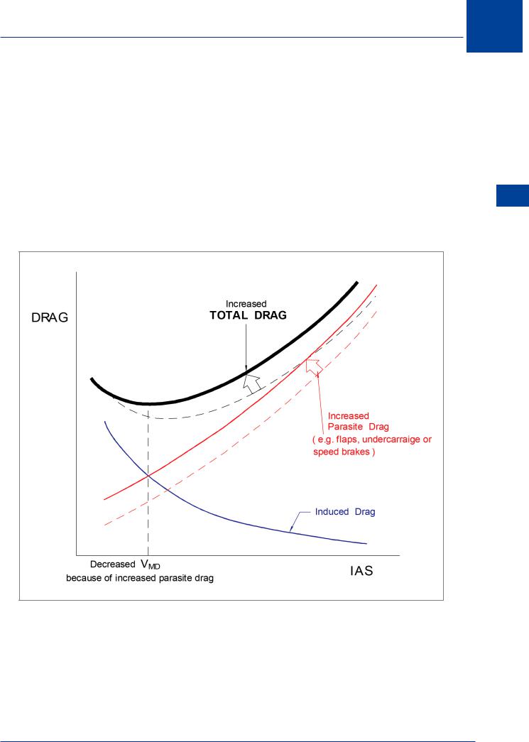
The Effect of Configuration on Total Drag
Extension of the landing gear, air brakes, or flaps will increase parasite drag but will not substantially affect induced drag. The effect of increasing parasite drag is to increase total drag at any IAS but to decrease the speed VMD compared to the clean aircraft, (Figure 6.19).
Figure 6.19
Drag 6
127
6 Drag
Drag 6
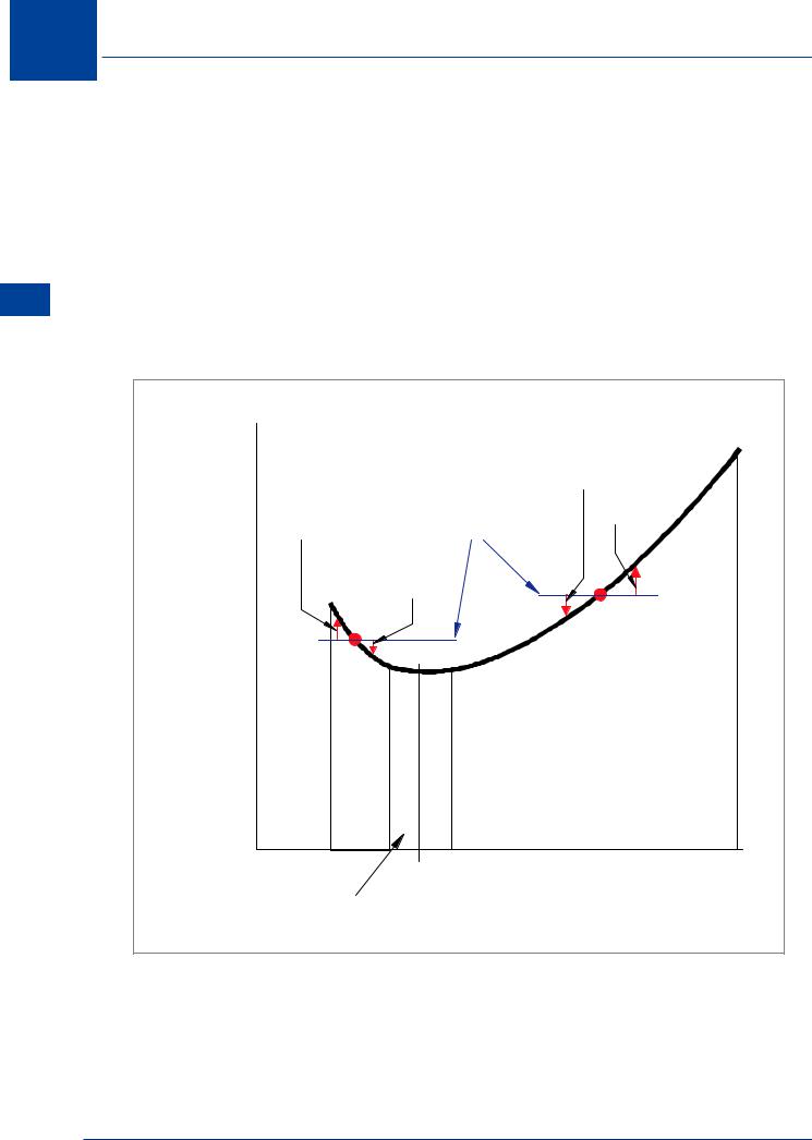
Speed Stability
For an aircraft to be in steady flight, the aircraft must be in equilibrium - there can be no out of balance forces or moments. When an aircraft is trimmed to fly at a steady speed, thrust and drag are equal. Therefore, when an aircraft is in steady flight it can be said that the term DRAG and the term ‘THRUST REQUIRED’ have the same meaning.
Consequently, an alternative to considering DRAG against IAS as in the graph of Figure 6.16, the term ‘THRUST REQUIRED’ can be substituted for drag.
For an aircraft in steady flight, if there is a variation in speed with no change in throttle setting, (which is called ‘THRUST AVAILABLE’), depending on the trim speed, there will be either an excess or a deficiency of thrust available. This phenomena is illustrated in Figure 6.20.
DRAG |
|
|
Thrust |
or |
|
|
|
Thrust |
|
|
Excess |
|
|
Thrust |
|
Required |
Thrust |
Thrust |
Deficiency |
|
Deficiency |
Available |
|
|
Thrust |
|
A |
|
Excess |
|
|
|
B |
|
|
|
Non |
|
|
|
Stable |
|
|
|
IAS |
|
Stable IAS region |
|
Region |
|
|
|
VMD |
|
IAS |
|
Neutral |
|
|
|
|
|
|
|
IAS |
|
|
|
Region |
|
|
Figure 6.20
128

Drag 6
If an aircraft is established in steady flight at point ‘A’ in Figure 6.20, lift is equal to weight and the thrust available is set to match the thrust required. If the aircraft is disturbed to some airspeed slightly greater than point ‘A’, a thrust deficiency will exist and, if the aircraft is disturbed to some airspeed slightly lower than point ‘A’, a thrust excess will exist. This relationship provides a tendency for the aircraft to return to the equilibrium of point ‘A’ and resume the original trim speed. Steady flight at speeds greater than VMD is characterized by a relatively strong tendency of the aircraft to maintain the trim speed quite naturally; the aircraft is speed stable.
Speed stability is an important consideration, particularly at speeds at and below VMD, most often encountered during the approach to landing phase of flight.
If an aircraft is established in steady flight at point ‘B’ in Figure 6.20, lift is equal to weight and the thrust available is set to match the thrust required. If the aircraft is disturbed and goes faster than the trim speed, there will be a decrease in drag giving an excess of thrust which will cause the aircraft to accelerate. If a disturbance slows the aircraft below the trim speed, there will be an increase in drag which will give a thrust deficiency causing the aircraft to slow further. This relationship is basically unstable because the variation of excess thrust to either side of point ‘B’ tends to magnify any original disturbance. Steady flight at speeds less than VMD is characterized by a tendency for the aircraft to drift away from the trim speed and the aircraft is speed unstable. If a disturbance reduces speed, it will naturally continue to reduce. If a disturbance increases speed, it will continue to accelerate until the thrust and drag are once more balanced. For this reason, the pilot must closely monitor IAS during the approach phase of flight. Any tendency for the aircraft to slow down must be countered immediately by a ‘generous’ application of thrust to quickly return to the desired trim speed.
Consider Figure 6.19. If an aircraft maintains a constant IAS in the speed unstable region, the addition of parasite drag by selecting undercarriage down or by deploying flaps has the benefit of reducing VMD which can improve speed stability by moving the speed stable region to the left.
At speeds very close to VMD an aircraft usually exhibits no tendency towards either speed stability or speed instability - the neutral IAS region.
Drag 6
129