
- •Textbook Series
- •Contents
- •1 Overview and Definitions
- •Overview
- •General Definitions
- •Glossary
- •List of Symbols
- •Greek Symbols
- •Others
- •Self-assessment Questions
- •Answers
- •2 The Atmosphere
- •Introduction
- •The Physical Properties of Air
- •Static Pressure
- •Temperature
- •Air Density
- •International Standard Atmosphere (ISA)
- •Dynamic Pressure
- •Key Facts
- •Measuring Dynamic Pressure
- •Relationships between Airspeeds
- •Airspeed
- •Errors and Corrections
- •V Speeds
- •Summary
- •Questions
- •Answers
- •3 Basic Aerodynamic Theory
- •The Principle of Continuity
- •Bernoulli’s Theorem
- •Streamlines and the Streamtube
- •Summary
- •Questions
- •Answers
- •4 Subsonic Airflow
- •Aerofoil Terminology
- •Basics about Airflow
- •Two Dimensional Airflow
- •Summary
- •Questions
- •Answers
- •5 Lift
- •Aerodynamic Force Coefficient
- •The Basic Lift Equation
- •Review:
- •The Lift Curve
- •Interpretation of the Lift Curve
- •Density Altitude
- •Aerofoil Section Lift Characteristics
- •Introduction to Drag Characteristics
- •Lift/Drag Ratio
- •Effect of Aircraft Weight on Minimum Flight Speed
- •Condition of the Surface
- •Flight at High Lift Conditions
- •Three Dimensional Airflow
- •Wing Terminology
- •Wing Tip Vortices
- •Wake Turbulence: (Ref: AIC P 072/2010)
- •Ground Effect
- •Conclusion
- •Summary
- •Answers from page 77
- •Answers from page 78
- •Questions
- •Answers
- •6 Drag
- •Introduction
- •Parasite Drag
- •Induced Drag
- •Methods of Reducing Induced Drag
- •Effect of Lift on Parasite Drag
- •Aeroplane Total Drag
- •The Effect of Aircraft Gross Weight on Total Drag
- •The Effect of Altitude on Total Drag
- •The Effect of Configuration on Total Drag
- •Speed Stability
- •Power Required (Introduction)
- •Summary
- •Questions
- •Annex C
- •Answers
- •7 Stalling
- •Introduction
- •Cause of the Stall
- •The Lift Curve
- •Stall Recovery
- •Aircraft Behaviour Close to the Stall
- •Use of Flight Controls Close to the Stall
- •Stall Recognition
- •Stall Speed
- •Stall Warning
- •Artificial Stall Warning Devices
- •Basic Stall Requirements (EASA and FAR)
- •Wing Design Characteristics
- •The Effect of Aerofoil Section
- •The Effect of Wing Planform
- •Key Facts 1
- •Super Stall (Deep Stall)
- •Factors that Affect Stall Speed
- •1g Stall Speed
- •Effect of Weight Change on Stall Speed
- •Composition and Resolution of Forces
- •Using Trigonometry to Resolve Forces
- •Lift Increase in a Level Turn
- •Effect of Load Factor on Stall Speed
- •Effect of High Lift Devices on Stall Speed
- •Effect of CG Position on Stall Speed
- •Effect of Landing Gear on the Stall Speed
- •Effect of Engine Power on Stall Speed
- •Effect of Mach Number (Compressibility) on Stall Speed
- •Effect of Wing Contamination on Stall Speed
- •Warning to the Pilot of Icing-induced Stalls
- •Stabilizer Stall Due to Ice
- •Effect of Heavy Rain on Stall Speed
- •Stall and Recovery Characteristics of Canards
- •Spinning
- •Primary Causes of a Spin
- •Phases of a Spin
- •The Effect of Mass and Balance on Spins
- •Spin Recovery
- •Special Phenomena of Stall
- •High Speed Buffet (Shock Stall)
- •Answers to Questions on Page 173
- •Key Facts 2
- •Questions
- •Key Facts 1 (Completed)
- •Key Facts 2 (Completed)
- •Answers
- •8 High Lift Devices
- •Purpose of High Lift Devices
- •Take-off and Landing Speeds
- •Augmentation
- •Flaps
- •Trailing Edge Flaps
- •Plain Flap
- •Split Flap
- •Slotted and Multiple Slotted Flaps
- •The Fowler Flap
- •Comparison of Trailing Edge Flaps
- •and Stalling Angle
- •Drag
- •Lift / Drag Ratio
- •Pitching Moment
- •Centre of Pressure Movement
- •Change of Downwash
- •Overall Pitch Change
- •Aircraft Attitude with Flaps Lowered
- •Leading Edge High Lift Devices
- •Leading Edge Flaps
- •Effect of Leading Edge Flaps on Lift
- •Leading Edge Slots
- •Leading Edge Slat
- •Automatic Slots
- •Disadvantages of the Slot
- •Drag and Pitching Moment of Leading Edge Devices
- •Trailing Edge Plus Leading Edge Devices
- •Sequence of Operation
- •Asymmetry of High Lift Devices
- •Flap Load Relief System
- •Choice of Flap Setting for Take-off, Climb and Landing
- •Management of High Lift Devices
- •Flap Extension Prior to Landing
- •Questions
- •Annexes
- •Answers
- •9 Airframe Contamination
- •Introduction
- •Types of Contamination
- •Effect of Frost and Ice on the Aircraft
- •Effect on Instruments
- •Effect on Controls
- •Water Contamination
- •Airframe Aging
- •Questions
- •Answers
- •10 Stability and Control
- •Introduction
- •Static Stability
- •Aeroplane Reference Axes
- •Static Longitudinal Stability
- •Neutral Point
- •Static Margin
- •Trim and Controllability
- •Key Facts 1
- •Graphic Presentation of Static Longitudinal Stability
- •Contribution of the Component Surfaces
- •Power-off Stability
- •Effect of CG Position
- •Power Effects
- •High Lift Devices
- •Control Force Stability
- •Manoeuvre Stability
- •Stick Force Per ‘g’
- •Tailoring Control Forces
- •Longitudinal Control
- •Manoeuvring Control Requirement
- •Take-off Control Requirement
- •Landing Control Requirement
- •Dynamic Stability
- •Longitudinal Dynamic Stability
- •Long Period Oscillation (Phugoid)
- •Short Period Oscillation
- •Directional Stability and Control
- •Sideslip Angle
- •Static Directional Stability
- •Contribution of the Aeroplane Components.
- •Lateral Stability and Control
- •Static Lateral Stability
- •Contribution of the Aeroplane Components
- •Lateral Dynamic Effects
- •Spiral Divergence
- •Dutch Roll
- •Pilot Induced Oscillation (PIO)
- •High Mach Numbers
- •Mach Trim
- •Key Facts 2
- •Summary
- •Questions
- •Key Facts 1 (Completed)
- •Key Facts 2 (Completed)
- •Answers
- •11 Controls
- •Introduction
- •Hinge Moments
- •Control Balancing
- •Mass Balance
- •Longitudinal Control
- •Lateral Control
- •Speed Brakes
- •Directional Control
- •Secondary Effects of Controls
- •Trimming
- •Questions
- •Answers
- •12 Flight Mechanics
- •Introduction
- •Straight Horizontal Steady Flight
- •Tailplane and Elevator
- •Balance of Forces
- •Straight Steady Climb
- •Climb Angle
- •Effect of Weight, Altitude and Temperature.
- •Power-on Descent
- •Emergency Descent
- •Glide
- •Rate of Descent in the Glide
- •Turning
- •Flight with Asymmetric Thrust
- •Summary of Minimum Control Speeds
- •Questions
- •Answers
- •13 High Speed Flight
- •Introduction
- •Speed of Sound
- •Mach Number
- •Effect on Mach Number of Climbing at a Constant IAS
- •Variation of TAS with Altitude at a Constant Mach Number
- •Influence of Temperature on Mach Number at a Constant Flight Level and IAS
- •Subdivisions of Aerodynamic Flow
- •Propagation of Pressure Waves
- •Normal Shock Waves
- •Critical Mach Number
- •Pressure Distribution at Transonic Mach Numbers
- •Properties of a Normal Shock Wave
- •Oblique Shock Waves
- •Effects of Shock Wave Formation
- •Buffet
- •Factors Which Affect the Buffet Boundaries
- •The Buffet Margin
- •Use of the Buffet Onset Chart
- •Delaying or Reducing the Effects of Compressibility
- •Aerodynamic Heating
- •Mach Angle
- •Mach Cone
- •Area (Zone) of Influence
- •Bow Wave
- •Expansion Waves
- •Sonic Bang
- •Methods of Improving Control at Transonic Speeds
- •Questions
- •Answers
- •14 Limitations
- •Operating Limit Speeds
- •Loads and Safety Factors
- •Loads on the Structure
- •Load Factor
- •Boundary
- •Design Manoeuvring Speed, V
- •Effect of Altitude on V
- •Effect of Aircraft Weight on V
- •Design Cruising Speed V
- •Design Dive Speed V
- •Negative Load Factors
- •The Negative Stall
- •Manoeuvre Boundaries
- •Operational Speed Limits
- •Gust Loads
- •Effect of a Vertical Gust on the Load Factor
- •Effect of the Gust on Stalling
- •Operational Rough-air Speed (V
- •Landing Gear Speed Limitations
- •Flap Speed Limit
- •Aeroelasticity (Aeroelastic Coupling)
- •Flutter
- •Control Surface Flutter
- •Aileron Reversal
- •Questions
- •Answers
- •15 Windshear
- •Introduction (Ref: AIC 84/2008)
- •Microburst
- •Windshear Encounter during Approach
- •Effects of Windshear
- •“Typical” Recovery from Windshear
- •Windshear Reporting
- •Visual Clues
- •Conclusions
- •Questions
- •Answers
- •16 Propellers
- •Introduction
- •Definitions
- •Aerodynamic Forces on the Propeller
- •Thrust
- •Centrifugal Twisting Moment (CTM)
- •Propeller Efficiency
- •Variable Pitch Propellers
- •Power Absorption
- •Moments and Forces Generated by a Propeller
- •Effect of Atmospheric Conditions
- •Questions
- •Answers
- •17 Revision Questions
- •Questions
- •Answers
- •Explanations to Specimen Questions
- •Specimen Examination Paper
- •Answers to Specimen Exam Paper
- •Explanations to Specimen Exam Paper
- •18 Index

Lift 5
Probability ofWakeTurbulence Encounter
Certain separation minima are applied by Air Traffic Control (ATC), but this does not guarantee avoidance. ATC applied separation merely reduces the probability of an encounter to a lower level, and may minimize the magnitude of the upset if an encounter does occur. Particular care should be exercised when following any substantially heavier aircraft, especially in conditions of light wind. The majority of serious incidents, close to the ground, occur when winds are light.
WakeTurbulence Avoidance
If the location of wake vortices behind a preceding or crossing aircraft are visualized, appropriate flight path control will minimize the probability of a wake turbulence encounter. Staying above and/or upwind of a preceding or crossing aircraft will usually keep your aircraft out of the generating aircraft’s wake vortex. Unfortunately, deviating from published approach and departure requirements in order to stay above/upwind of the flight path of a preceding aircraft may not be advisable. Maintaining proper separation remains the best advice for avoiding a wake turbulence encounter.
Ground Effect
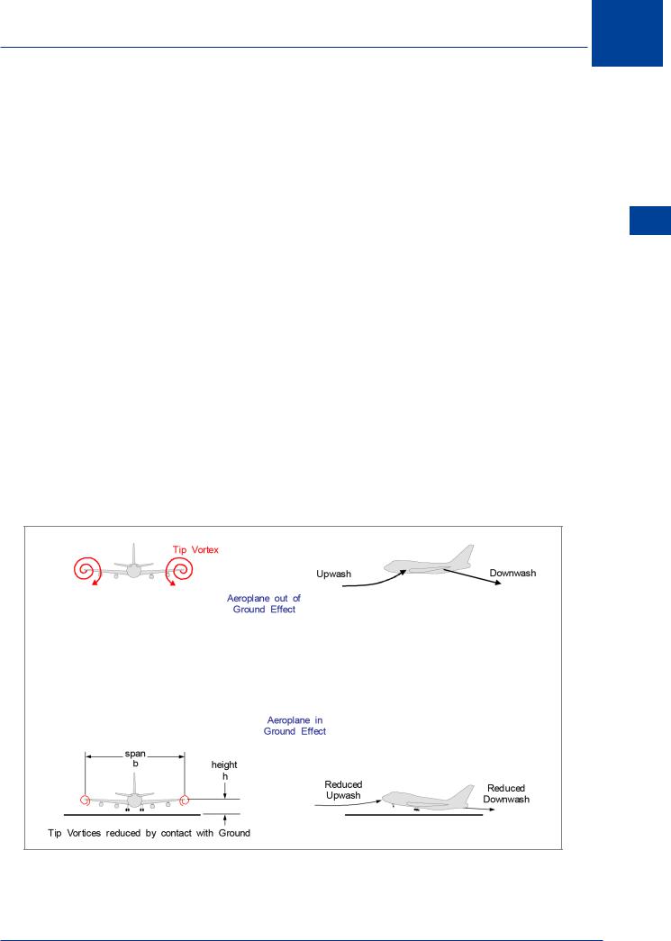
When landing and taking off, the closeness of the wing to the ground prevents full development of the trailing vortices, Figure 5.21, making them much weaker. Upwash and downwash are reduced, causing the effective angle of attack of the wing to increase, (ref: Figure 5.15). Therefore, when an aircraft is “in ground effect” lift will generally be increased and induced drag (CDi) will be decreased. In addition, the reduced downwash will affect both longitudinal stability because of CP movement, and the pitching moment because of changes to the effective angle of attack of the tailplane, (Ref: Figure 5.23).
Figure 5.21
Lift 5
91

5 Lift
Lift 5
The Impact of Ground Effect
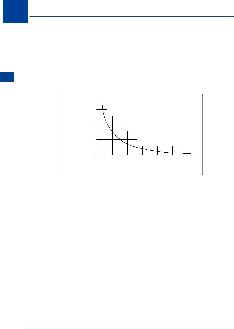
The influence of ground effect depends on the distance of the wing above the ground. A large reduction in CDi will take place only when the wing is very close to the ground, (within half the wingspan).
For a representative aircraft with a 40 m span, (Ref. Figure 5.22):
•At a height of 40 m, the reduction in CDi is only 1.4%.
•At a height of 10 m, the reduction in CDi is 23.5%, but
•At a height of 4 m, the reduction in CDi is 47.6%
|
60 |
|
|
|
|
|
|
|
|
|
|
|
Percent |
50 |
|
|
|
|
|
|
|
|
|
|
|
Reduction |
|
|
|
|
|
|
|
|
|
|
|
|
in |
40 |
|
|
|
|
CL |
Constant |
|
|
|
||
Induced |
|
|
|
|
|
|
|
|||||
Drag |
30 |
|
|
|
|
|
|
|
|
|
|
|
Coefficient |
|
|
|
|
|
|
|
|
|
|
|
|
|
|
|
|
|
|
|
|
|
|
|
|
|
CDi |
20 |
|
|
|
|
|
|
|
|
|
|
|
10 |
|
|
|
|
|
|
|
|
|
|
|
|
|
|
|
|
|
|
|
|
|
|
|
|
|
|
0 |
0.1 |
0.2 |
0.3 |
0.4 |
0.5 |
0.6 |
0.7 |
0.8 |
0.9 |
1.0 |
1.1 |
|
0 |
|||||||||||
|
|
|
Ratio of wing height |
to span |
(h/b) |
|
|
Figure 5.22
The height of the wing above the ground when the aircraft is in the landing attitude is influenced by its mounting position on the fuselage. From the graph in Figure 5.22 it can be seen that the last few metres makes a big difference to the reduction of CDi. In general, it can be said that a low wing aircraft will experience a greater degree of ground effect than an aircraft with a high mounted wing.
92

Lift 5
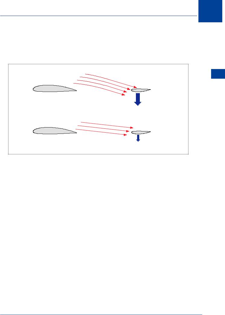
High and LowTail Characteristics
While ground effect may possibly change the aerodynamic characteristics of the tailplane in its own right, a low mounted tailplane will have its effective angle of attack modified by the changing downwash angle behind the wing. A high mounted tailplane may be outside the influence of the changing downwash angle and not suffer the same disadvantages.
Normal |
5 |
Downwash |
|
|
Lift |
Down load |
|
on |
Tailplane |
Downwash Decreased |
|
by Ground Effect |
|
Decreased |
|
Down load |
|
on Tailplane |
Figure 5.23
93

5 Lift
Lift 5
" NORMAL" DOWNWASH
POSITIVE
CAMBER
Tailplane (Every illustration)
NEGATIVE
CAMBER
SYMMETRICAL
REDUCED
DOWNWASH
ANGLE
INCREASED
UPFORCE
DECREASED
DOWNFORCE
DECREASED
DOWNFORCE
Figure 5.24
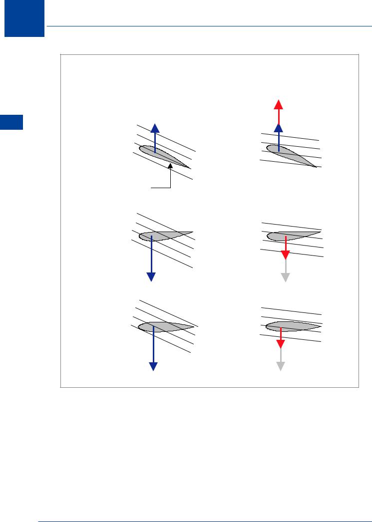
Influence ofTailplane Camber on Pitching Moment
It can be seen from Figure 5.24 that the type of tailplane camber does not influence the pitching moment generated when downwash from the wing changes. Decreased downwash will always result in an aircraft nose-down pitching moment. The opposite will be true of increased downwash.
Downwash will change not only because of ground effect, but also when flaps are operated
and when a shock wave forms on the wing at speeds higher than MCRIT, so appreciation of this phenomena is a key element towards a full understanding of Principles of Flight.
94

Lift 5
Lift 5
Figure 5.25
Tailplane Angle of Attack
Angle of attack is the angle between the chord line and the relative airflow. The relative airflow has three characteristics:
•Magnitude - the speed of the aircraft through the air; the True Airspeed (TAS)
•Direction - parallel to and in the opposite direction to the aircraft flight path, and
•Condition - unaffected by the presence of the aircraft.
Air flowing off the wing trailing edge (downwash) cannot be defined as relative airflow because it does not conform to the definitions. Neither is it possible to think strictly of a tailplane angle of attack. Airflow which has been influenced by the presence of the aircraft (direction of flow and dynamic pressure) must be thought of as Effective Airflow. And the angle between the chord line and the effective airflow must be thought of as Effective Angle of Attack.
Consider Figure 5.25. Airflow from direction A gives the tailplane zero (effective) angle of attack. Airflow from direction E, F or G would be an increase in (effective) angle of attack. If airflow from direction G is now considered, flow from F, E, A, B, C or D would be a decrease in (effective) angle of attack. The term “negative angle of attack” is not used.
95