

L = ½ ρ V 2 C |
|
S |
transposed becomes: |
|
C |
|
= |
|
|
|
|
L |
|
|
|
L |
|
L |
|
½ |
ρ V2 S |
|
|||||||||
|
|
|
|
|
|
|
|
||||||||
|
|
|
|
|
|
|
|
|
|
||||||
As density, lift and wing area are constant, this can be written : |
C |
1 |
|||||||||||||
V2 |
|||||||||||||||
|
|
|
|
|
|
|
|
|
|
|
|
L |
|||
30% above minimum level flight speed can be written as 1.3V |
|
|
|
|
|||||||||||
The proportional change in CL is therefore |
1 |
= |
|
1 |
|
|
= |
|
0.59 = 59% |
||||||
(1.3)2 |
|
1.69 |
|
|
|||||||||||
Lift 5
Lift 5
While maintaining level flight at a speed 30% above minimum level flight speed, the CL would be 59% of CLMAX
Review:
Lift must balance weight in straight and level flight, so at any moment in time, weight and the lift required is constant.
•To maintain constant lift if density varies because of altitude change, the TAS must be changed.
•If altitude is increased, density decreases, so TAS must be increased.
•If altitude is decreased, density increases, so TAS must be decreased.
Maintaining a constant IAS will compensate for density changes.
•To maintain constant lift if speed is changed at a constant altitude (density), the angle of attack must be adjusted.
•If speed is increased, angle of attack must be decreased, (if speed is doubled, angle of attack must be decreased to make CL one quarter of its previous value).
•If speed is decreased, angle of attack must be increased, (if speed is halved, angle of attack must be increased to make CL four times its previous value).
•Generally, a cruise speed is chosen so the aircraft operates at its optimum angle of attack (L/D MAX - approximately 4°).
75

5 Lift
Lift 5
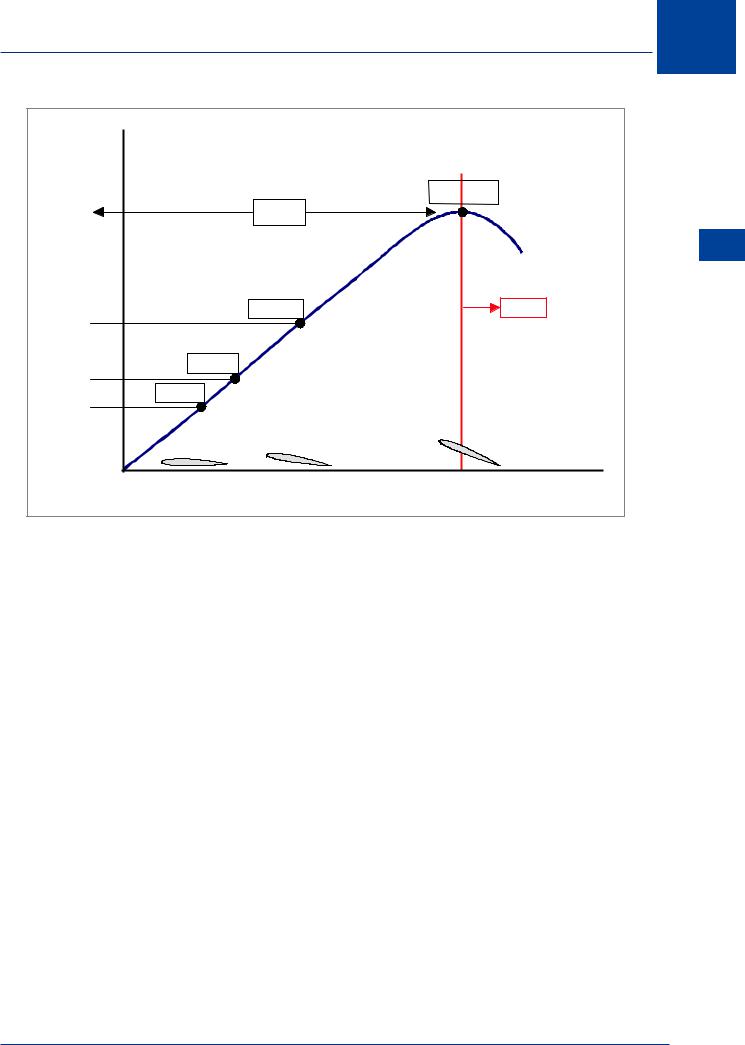
The Lift Curve
Figure 5.4 shows the lift curve of an aerofoil section, with lift coefficient (CL) plotted against angle of attack. It is evident that the section is symmetrical because no lift is produced at zero angle of attack.
The lift curve is a convenient way to illustrate the properties of various configurations and will be used extensively throughout these notes.
Lift coefficient increases with angle of attack up to a maximum (CLMAX), which corresponds to the “Critical” angle of attack. Continuing to increase the angle of attack beyond this point makes it impossible for the airflow to maintain its previous smooth flow over the contour of the upper surface, and lift will reduce. This phenomena, stall, will be discussed in detail later.
Interpretation of the Lift Curve
•To generate a constant lift force, any adjustment in dynamic pressure must be accompanied by a change in angle of attack. (At CL less than CLMAX).
•For a constant lift force, each dynamic pressure requires a specific angle of attack.
•Minimum dynamic pressure is determined by the maximum lift coefficient (CLMAX), which occurs at a specific angle of attack (approximately 16°).
•The angle of attack for CLMAX is constant. (This is true for a given configuration).
•If more lift is required due to greater operating weight, a greater dynamic pressure is required to maintain a given angle of attack.
•The greater the operating weight, the higher the minimum dynamic pressure.
To use the lift formula with specific values, it is necessary to convert each item to SI units.
The mass of the aircraft is 60 000 kg. To convert to a weight, the mass must be multiplied by the acceleration of gravity (9.81 m/s2). The wing area is 105 m2. Density is the ICAO Standard Atmosphere sea level value of 1.225 kg/m3.
The speed resulting from the calculation will be in m/s. There are 6 080 ft in one nautical mile and 3.28 ft in one metre.
The lift formula: |
L = ½ ρ V2 C |
L |
S |
|
|
|
|
|
|
|
|
|
|
|
|
|
|
|
|
|
|
|
|
|
|
|
|
|
|
when transposed to calculate speed becomes: |
V |
= |
|
L |
|
|
|||
|
½ ρ CL |
S |
|
||||||
|
|
|
|
|
|
|
|
||
76
|
Lift |
5 |
|
CL |
|
|
Knots |
|
1.532 |
CLMAX |
|
|
|
5 |
|
|
Lift |
|
STALL |
|
0.863 |
|
|
0.552 |
|
|
0.384 |
|
|
|
ANGLE OF ATTACK ( DEGREES ) |
|
Figure 5.4 Typical lift curve
Please answer the following questions: (Answers are provided on page 99)
a.How many newtons of lift are required for straight and level flight?
b.Calculate the airspeed in knots for each highlighted coefficient of lift.
c.What is the lowest speed at which the aircraft can be flown in level flight?
d.What coefficient of lift must be used to fly as slowly as possible in level flight?
e.Does each angle of attack require a particular speed?
f.As speed is increased, what must be done to the angle of attack to maintain level flight?
g.At higher altitude air density will be lower; what must be done to maintain the required lift force if the angle of attack is kept constant?
h.At a constant altitude, if speed is halved, what must be done to the angle of attack to maintain level flight?
77
5 Lift
|
|
|
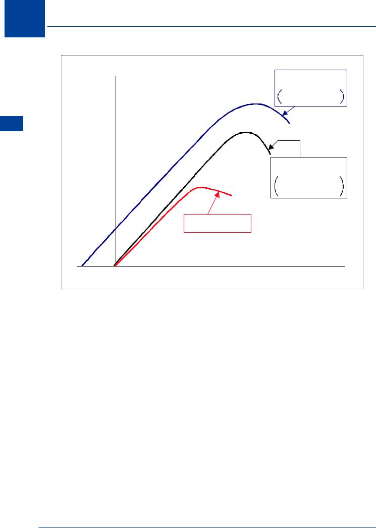
CAMBERED |
|
CL |
|
WITH 12% THICKNESS |
|
|
CAMBER GIVES |
|
|
|
|
|
|
|
|
INCREASE IN CLMAX |
Lift 5 |
COEFFICIENT |
|
SYMMETRICAL |
|
LIFT |
|
|
|
|
WITH 12% THICKNESS |
|
|
|
|
|
|
SECTION |
|
GREATER THICKNESS |
|
|
GIVES 70% INCREASE |
|
|
|
|
IN CLMAX |
|
|
|
SYMMETRICAL |
|
|
|
WITH 6% THICKNESS |
|
|
0 |
SECTION ANGLE OF ATTACK (DEGREES) |
|
|
|
Figure 5.5
Using the above graph, please answer the following questions: (Answers on page 100)
a.Why does the cambered aerofoil section have a significantly higher CLMAX?
b.For the same angle of attack, why do the symmetrical aerofoil sections generate less lift than the cambered aerofoil section?
c.Why does the cambered aerofoil section of 12% thickness generate a small amount of lift at slightly negative angles of attack?
d.For a given angle of attack, the symmetrical aerofoil section of 6% thickness generates the smallest amount of lift. In what way can this be a favourable characteristic?
e.What are the disadvantages of the symmetrical aerofoil section of 6% thickness?
78