


Chapter
13
AC Electrics - Practical Aircraft Systems
Power Distribution . . . |
. . . . . . . . . . . . . . |
. . |
. . |
. . |
. . |
. |
. |
221 |
The Split Bus System . . |
. . . . . . . . . . . . . . |
. . |
. . |
. . |
. . |
. . |
|
.221 |
Parallel Bus Bar System . . |
. . . . . . . . . . . . . . |
. . |
. . |
. . |
. . |
. |
. |
224 |
Questions . . . . . . |
. . . . . . . . . . . . . . |
. . |
. . |
. . |
. . |
. . |
|
.226 |
Answers |
|
|
|
|
|
|
|
228 |
219
13 AC Electrics -Practical Aircraft Systems
|
|
|
Generator 1 |
|
|
|
|
|
|
|
|
From APU |
Generator |
|
|
|
CSD |
|
|
|
|
|
|
|
|
|
|
SystemsAircraftPracticalElectrics AC 13 |
|
barsBus panel |
Engine/Wing |
Disconnect |
|
|
|
|
|
|
|
Generator13.1Figure Feeder Lines |
|
loadTo |
Line Current Transformers |
|
|
|
|
|
|
|
|
|
|||
|
|
FlightdeckCB |
|
|
|
|
|
|
|
|
|
|
|
|
|
|
Generator |
Breaker 1 |
Generator |
Breaker 2 |
APU Generator |
Breaker |
Engine/Wing |
Disconnect |
|
CSD Generator 2 |
|
220

AC Electrics - Practical Aircraft Systems 13
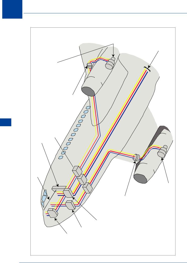
Power Distribution
In a very basic form, Figure 13.1 shows the general layout of an electrical distribution system for a twin jet aircraft. One generator is driven by and mounted on each engine and one generator is mounted on the APU (not shown). The feeder cables from each generator are routed through the aircraft wings and fuselage to meet at a central distribution compartment usually beneath the flight deck or cabin floor. This distribution compartment will house many of the components already described: GCBs, BTBs GCUs or voltage regulators, current transformers, main bus bars and bus bar protection circuitry, battery and battery charger. Bus bars and bus bar extensions may be found on the flight deck behind the rear, side and overhead circuit breaker panels.
A schematic diagram for this type of system is shown at Figure 13.2.
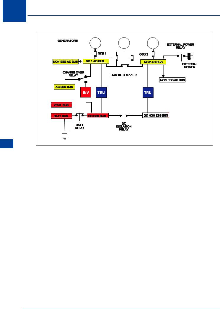
The Split Bus System
The Split Bus Bar System uses 115 V/ 200 V/ 400 Hz/ 3 phase constant frequency alternators as the primary power source. They are not designed to run in parallel and therefore do not require complex paralleling and load sharing circuits. A 28 V DC supply is provided by two Transformer Rectifier Units (TRUs) which convert 115 V AC to 28 V DC from the two separate AC bus bars. A battery is provided which will provide power to start the APU and limited emergency power to the essential bus bars, or to supply air and electrics on the ground when the engine driven generators are off line.
If, in the circuit shown in Figure 13.2, either alternator should fail, then the main bus bars are automatically connected by the Bus Tie Breaker and they will now serve as one bus bar. Power supplies to all the bus bars are thereby maintained. The APU may then be started in flight and its generator can be used to restore full power by connecting to AC bus 1 or bus 2. While each alternator separately supplies its own AC non-essential services and the associated TRU, the essential AC loads are supplied from only the No. 1 main bus bar via a changeover relay. In particular, note that the main AC bus bars are normally isolated from one another, i.e. the alternators are not paralleled
If both alternators should fail, then the AC non-essential services, which are normally supplied from the main AC bus bars, are isolated.
The changeover relay between the No. 1 main bus bar and the essential AC bus bar will automatically switch over. This causes the essential AC bus bar to be connected to an Emergency Static Inverter, which should, if the batteries are in a fully charged state, supply the essential AC bus bars for 30 minutes.
AC Electrics - Practical Aircraft Systems 13
221
13 AC Electrics -Practical Aircraft Systems
Systems Aircraft Practical - Electrics AC 13
No. 1 |
APU |
No. 2 |
Figure 13.2 Split bus system
Under normal conditions, the DC supply in Figure 13.2 is obtained from the two independent TRUs and the batteries.
The No. 1 TRU supplies essential DC loads and the No. 2 TRU supplies non-essential DC loads.
In normal operation the two bus bars supplying the essential and non-essential DC loads are connected together by the Isolation Relay. The batteries are connected directly to the Battery Bus Bar, and through the Battery Relay they will feed the essential DC bus bar.
If, one alternator fails then both TRUs are still supplied through the now closed contacts of the bus tie breaker, and will still supply all of the DC consumers.
If, however, both alternators fail, the DC Isolation Relay will open and separate the essential and non-essential bus bars.
Non-essential loads will now no longer be powered, but the AC and DC essential loads will be fed from the battery bus bar (the AC loads from the static inverter).
External power or supplies from the APU can be used to feed all electrical services in the aircraft on the ground, but the APU generator may only be capable of supplying one bus bar in flight.
222
AC Electrics - Practical Aircraft Systems 13
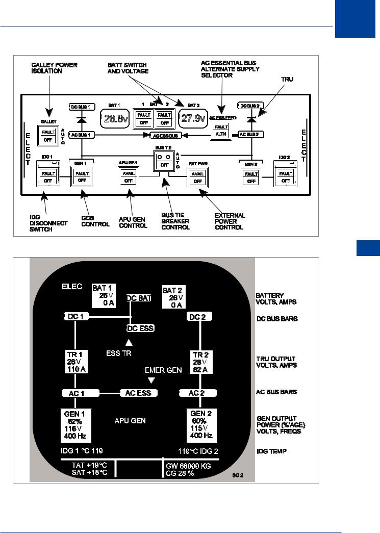
Figure 13.3 A320 split bus control panel
Figure 13.4 A320 ECAM display
AC Electrics - Practical Aircraft Systems 13
223