

AC Electrics - Alternators 12
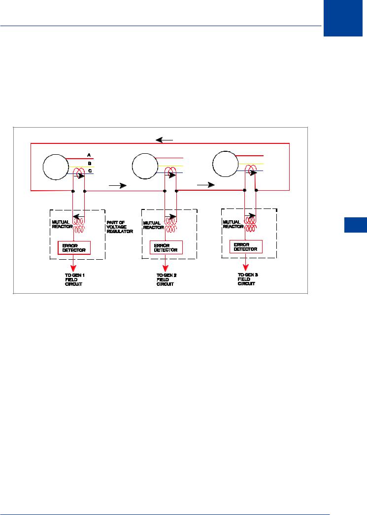
The mutual reactor is a phase shifting transformer which ensures that the error detector only detects that part of the current which is 90° out of phase with the voltage (reactive load). The error signal is then amplified and correcting signals are sent to the generator field circuit to increase the voltage on the low voltage generator and reduce the voltage of the higher voltage generator to balance the reactive load.
Reactive load sharing is controlled by the Voltage Regulators matching voltage outputs (field excitation).
|
|
5 A |
|
|
GEN1 |
|
GEN2 |
|
GEN3 |
7 A |
5 A |
4 A |
5 A |
4 A |
2 A |
|
1 A |
|
1 A |
|
|
|
|
12 |
|
|
|
|
AC Electrics - Alternators |
Figure 12.13 Reactive load sharing circuit
Load Sharing General
It is typical to run three and four generator systems in parallel but most modern twin engine aircraft with two generators run the generators in isolation (Split Bus System).
In those three and four generator systems the load sharing circuits operate as shown above but are extended to cater for the required number of generators.
If any generator in a parallel system is not connected in parallel then it will not be connected to the load sharing circuits either.
REMEMBER: Real load sharing |
- |
speed, frequency, torque (CSDU) |
Reactive load sharing |
- |
excitation current, field current |
|
|
(Voltage Regulator) |
Alternator Cooling
The heat generated in the alternator stator windings due to the current flow through them means that some form of cooling system is required. Those systems with frequency wild generators or constant frequency generators with separate CSDUs typically use ram air cooling in flight and some means to induce an airflow on the ground. IDGs or IDUs use their oil to cool the stators which is then cooled in its own oil cooler.
201

12 AC Electrics -Alternators
Generator Fault Protection
When constant frequency alternators are paralleled, then the requirement for other Control and Protection devices become apparent.
There follows a non-exhaustive list of some of those devices:
•Bus Tie Breakers (BTBs).
•Discriminatory circuits.
•Differential Fault Protection circuits.
•Synchronizing Units.
•Failure Warning systems.
•Load meters.
•Voltage and Frequency meters.
•Generator Control Units (GCUs).
Alternators - Electrics AC 12
Bus Tie Breakers (BTBs)
A bus tie breaker connects two bus bars together. In a paralleled system it connects an alternator to the synchronizing bus bar. The synchronizing bus bar allows two or more alternators to be connected in parallel with each other while the BTBs are closed. Control of the BTB can be automatic or manual dependent on the type of aircraft. Correct signals from a Synchronizing Unit (monitoring phase frequency and voltage) must be available before the BTB will close and put the alternator in parallel with another. In a paralleled system the BTBs are normally closed. In a Split Bus system (non paralleled) the BTB is normally open.
Visual indication of the position of the BTBs is given by indicators on the electrical control panel or the electronic display panel.
Discriminatory Circuits
When alternators are paralleled, Discrimination Circuitry is required to ensure that in the event of a fault only the faulty system is disconnected from the appropriate bus bar. This is achieved by selective switching of the GCBs and BTBs.
Differential Fault Protection
Control and protection devices must be included within the power supply circuits. These will monitor system performance and appropriately operate the relevant circuit breakers, GCBs BTBs etc. This may be achieved by a component known as a bus power control unit (BPCU) which monitors the system by current transformers placed at each generator and at each bus bar. It will isolate a defective generator or faulty bus bar and reconfigure the electrical system to maintain the maximum usage.
Protection is provided for:
•Over / Under Voltage
•Over / Under Frequency
•Over / Under Excitation.
•Differential Current Faults, (short circuits between bus bars or bus bar to ground, or open circuit faults unbalancing phase outputs).
202

AC Electrics - Alternators 12
Synchronizing Units
Before the alternator can be connected to a bus bar which is common to another alternator its voltages, frequency and phase sequence must be within very strict limits and in the same order. The Synchronizing Unit ensures that these values are within limits before it will allow connection to a common bus bar. There are two methods in use:
•Automatic Control
•Manual (Dark Lamp) Method
Automatic control will not allow the BTB or GCB to close and parallel the generators until the voltage, frequency and phase sequence of the oncoming generator is within limits. This may be achieved by circuitry within a bus bar protection control unit or in the Generator Control Units (GCUs) of a modern IDG system.
The Manual (Dark Lamp) method is a much older method but remains in use on a few aircraft. Synchronizing Lights on the alternator control panel will show when there are differences between phases of two supplies. Synchronization is indicated when the lamps are “dark” and then the BTB, or GCB, can be closed by means of the manual switch.
Generator Failure Warning Light
A Generator Failure Warning Light will illuminate when its associated GCB is tripped. The Centralized Warning System will operate simultaneously with the Generator Warning Light and in some aircraft Aural Warnings are generated.
Aircraft with electronic systems management display units will show the failure and the associated schematic display.
Load Meters
kW / kVAR Meters are used in paralleled alternator systems to indicate the Real Power (kW) or the Reactive Power (kVAR) output. Only one meter may be used to indicate both parameters, selection of a switch will determine which of the two is shown. Typically the switch is selected so that the kW output is normally displayed.
The Real Load is the part of the alternator output which is available to do work at the bus bar. The Reactive Load is the part of the alternator output which is used to create electromagnetic and electrostatic effects in the circuits. It is the so-called Wattless Load which is the vector sum of the inductive and capacitive currents and voltages.
Load meters on modern electronic display units may only show a percentage of the maximum power being taken.
Voltage and Frequency Meters
Voltage and frequency indications are also provided for each generator. Typically only one voltmeter and one frequency meter is provided in systems with several alternators in circuit. The voltage or frequency of any alternator can be selected by a Multi-position Switch. The switch can usually be positioned to show not only the supply frequency and voltage of the engine driven alternators, but also that of the auxiliary power unit, the ground power unit or the Emergency Ram Air Turbine, if provided.
AC Electrics - Alternators 12
203

12 AC Electrics -Alternators
Generator Control Unit (GCU)
In a modern generator control system a Generator Control Unit (GCU) houses circuitry to provide many functions of power control and protection. A typical GCU will monitor generator output and provide voltage regulation by controlling the exciter field current. Protection circuitry will monitor for overvoltage and overcurrent, frequency, phase sequence and differential current protection. A GCU will be provided for each generator and they may work as a team with the BPCU in controlling fault isolation switching.
The GCU may also house an Exciter Control Relay otherwise known as a Generator Control Relay or Generator Field Relay. The exciter control relay controls the exciter field current supply to the generator field. In the event of a dangerous fault occurring (over excitation or overvoltage) the fault protection circuit will open the exciter control relay which will cause the generator output to fall to a residual value making it safe. The GCU will also open the generator circuit breaker (GCB) to disconnect the generator from its bus bar. (In a paralleled system power would be maintained to the generator bus bar from the other generators through the BTB).
Alternators - Electrics AC 12
Emergency Supplies
In the unlikely event of some, or the entire engine driven AC power generation systems on the aircraft failing, alternative methods of supply must be made available. Some alternative means of providing AC are listed below:
•Ram Air Turbine (RAT)
•Auxiliary Power Unit (APU)
•Static Inverter.
•Hydraulic Motor driven generator.
The Ram Air Turbine (RAT)
The Ram Air Turbine (RAT or ELRAT), when lowered into the slipstream of an aircraft in flight, will produce an emergency source of AC power. The output is controlled at a nominal 115 V/ 200 V/ 400 Hz/ 3 phase; it will give limited operation only of Flight Instrument and Radio services in the event of total alternator failure. (RATs driving an electrical generator have been largely replaced by RATs driving a hydraulic pump, as modern aircraft are more dependent on hydraulic power to power the primary flying controls in an emergency).
The Auxiliary Power Unit (APU)
The Auxiliary Power Unit (APU) is usually a small gas turbine engine mounted in the aircraft tailcone. This engine runs at a constant speed and has its own protection devices in the event of a fire, low oil pressure, high oil temperature, overspeed or overheat.
It can be used, among other things, to drive a 115 V/ 200 V/ 400 Hz/ 3 phase alternator for ground servicing supplies, or, in some aircraft, for emergency supplies in the air.
The APU alternator cannot be paralleled with the engine driven alternators, and will only supply power to the bus bars when no other source is feeding them.
204