

AC Electrics - Alternators
Rotating Field alternators make up the majority in use. From the previous sections it will be seen that in this type of alternator the field is in the rotor and the phase windings form the stator.
There are two types of rotating field alternator in use on aircraft:
•Brushed alternators.
•Brushless alternators.
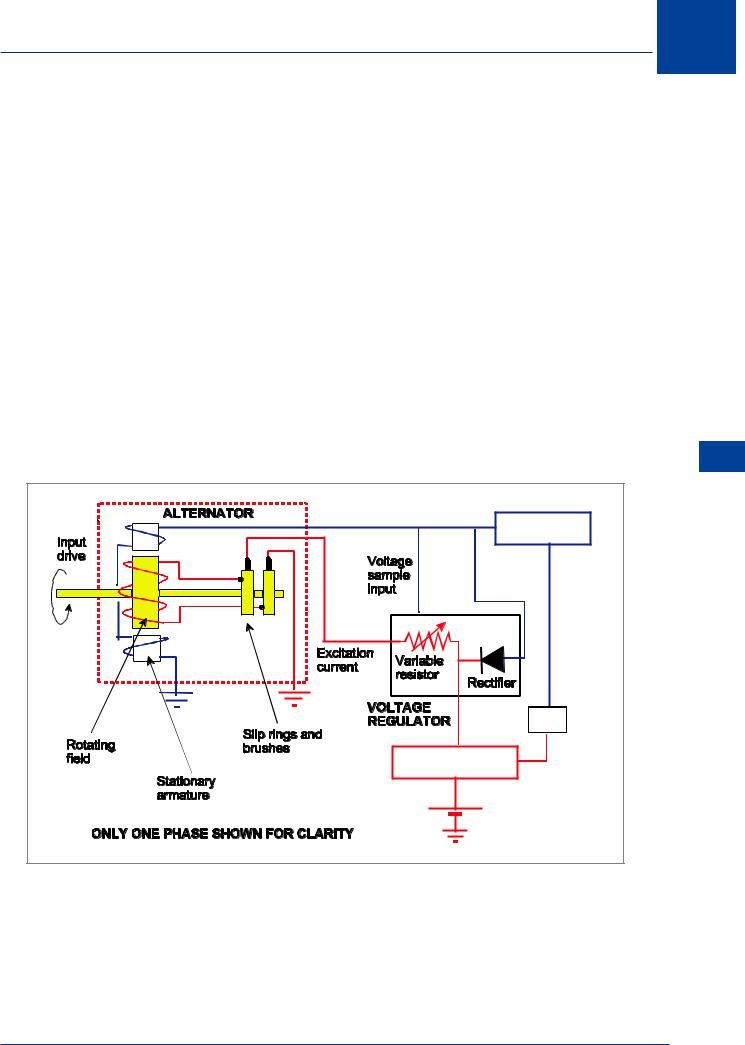
Brushed Alternators
The current supply for the excitation of the rotor field can be provided initially from the aircraft DC bus bar (battery) and then subsequently by rectified AC. The DC current is directed through brushes and slip rings to the rotating field.
Control of the excitation current is by the voltage regulator which samples the alternator output (115 V AC) and adjusts the excitation current to maintain the correct voltage irrespective of the alternator speed and loads.
The voltage regulator in its simplest form is a variable resistance connected in series with the field coil (the principle of the carbon pile regulator in Chapter 6, page 93 ).
115 V AC BUS |
TRU |
28 V DC BUS BAR |
Figure 12.7 Brushed alternator
12
AC Electrics - Alternators 12
193
12 AC Electrics -Alternators
Alternators - Electrics AC 12
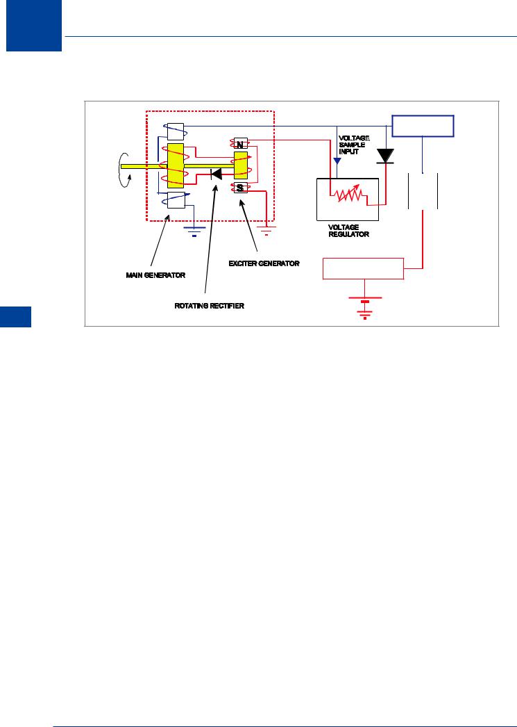
Brushless Alternators
115 V AC BUS |
TRU |
28 V DC BUS BAR |
Figure 12.8 Brushless alternator
A brushless alternator incorporates an exciter generator mounted on the same shaft as the main generator. The purpose of the exciter generator is to provide a current for the main generator rotating field. The rotating rectifier converts the AC produced in the exciter armature to DC required for the main rotor field supply.
Voltage regulation is effected by controlling the exciter field strength and thereby the current strength at the main rotor field coil.
Brushless alternators have some advantages over brushed alternators:
•They are very reliable
•There are no brush wear problems
•They have a high power to weight ratio
Modern brushless alternators may have a third generator on the same shaft called a Permanent Magnet Generator (PMG) which provides excitation current for its exciter generator. Alternator output is usually 115 V/200 V/400 Hz/3 phase.
There are two basic types of brushless alternator:
•Externally excited. (No residual magnetism in the exciter)
•Self-excited. (Some residual magnetism in the exciter)
Frequency Wild Alternators
If an alternator is driven directly from the engine gearbox then its speed, and therefore the frequency of its output, will vary directly with engine speed. An output from such a generator is said to be Frequency Wild.
NOTE: The connection of two frequency wild generators in parallel is not possible.
194
AC Electrics - Alternators 12
Frequency wild alternators are usually used on aircraft to power the electrical de-icing systems, where the resistances that make up the heater mats are not affected by changing frequencies.
Obtaining a Constant Frequency Supply from a Frequency Wild System
Inverters can be used to give a constant frequency output from a frequency wild supply. The frequency wild AC is rectified to DC which is used to power a Static Inverter which then converts DC to constant frequency AC.
Constant Frequency Alternators
If an alternator can be driven at a constant speed, then the output frequency will be constant. Driving the engine at a constant speed is not a practical proposition so a device is required to keep the speed of the alternator constant irrespective of the engine speed.
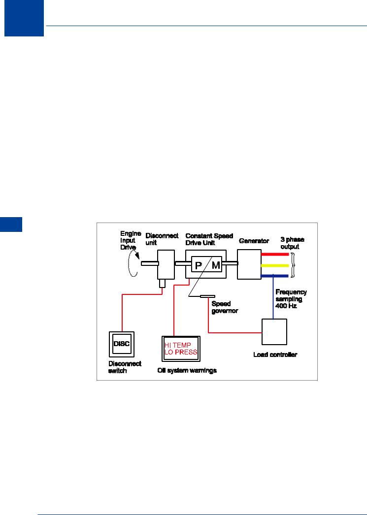
Constant Speed Generator Drive Systems
The Constant Speed Drive Unit (CSDU) consists of an engine driven hydraulic pump, the output of which drives a hydraulic motor which itself in turn drives the alternator.
The oil which forms the fluid, through which the mechanism operates and also facilitates lubrication and cooling, is contained within a reservoir, entirely separate from the engine oil system. The output of the hydraulic pump, and therefore the speed of the hydraulic motor, depends on the angle of a swash plate within the pump. The angle of the swash plate is controlled by a device called a speed governor. The speed governor is controlled by the load controller which senses the output frequency of the alternator and is responsible for increasing or decreasing the torque output of the CSDU to the alternator drive.
Most CSDUs are capable of maintaining the alternator output frequency within 5% of 400 Hz (380 - 420 Hz).
In the event of a mechanical failure in the alternator, the CSDU is protected by a Quill Drive; this is the equivalent of a weak link which will break before any major damage can be caused.
The CSDU operates in one of three modes: overdrive, straight through drive or underdrive.
• |
Overdrive |
= engine speed less than generator speed |
• |
Straight through drive = engine speed same as generator speed |
|
• |
Underdrive |
= engine speed greater than generator speed |
Some constant frequency generators have their CSDU and generator combined in one unit called an Integrated Drive Unit (IDU) or Integrated Drive Generator (IDG).
CSDU Fault Indications in the Cockpit
There are several indications in the cockpit associated with the Constant Speed Drive Unit and the problems which might occur with it. The two main ones are:
•Low Oil Pressure Warning Lights. These will illuminate when the oil pressure drops below a predetermined minimum value.
•High Oil Temperature warning. This allows the CSDU oil outlet temperature to be monitored.
AC Electrics - Alternators 12
195
12 AC Electrics -Alternators
The Drive Disconnect Unit (Dog Clutch Disconnect)
In the unlikely event of a malfunction in the CSDU or the alternator, the engine input drive to the CSDU can be disconnected. This will allow both the drive unit and the alternator to become stationary, thus eliminating any chance that the malfunction will affect engine performance.
The disconnection can be carried out at any time the engine is running, although reconnecting may only be done “manually” on the ground following shut down of the engine.
Figure 12.9 illustrates a CSDU and the drive disconnect mechanism. The disconnect unit is operated by the selection of a momentary action ‘Drive Disconnect’ switch by the pilot. This operates a solenoid which causes a mechanical separation of the input drive from the engine to the constant speed unit. Exceptionally, some aircraft may allow automatic disconnection of the generator drive by a generator control unit (GCU) under certain fault conditions.
Some IDGs are known as Permanent Magnet Generators (PMGs). The generator has three separate generators on the same shaft: a permanent magnet generator which provides for initial excitation of the exciter generator which controls the main generator field. This type of generator is invariably controlled by a Generator Control Unit (GCU).
Alternators - Electrics AC 12
Figure 12.9
Variable Speed Constant Frequency Power Systems (VSCF)
A variable speed constant frequency system (VSCF) uses a frequency wild generator driven by the engine and the variable frequency output is electronically converted into a constant frequency 400 Hz supply. The conversion is achieved by a generator converter control unit (GCCU) which first passes the variable frequency supply through a full wave rectifier where it is rectified and filtered and then to an inverter where it is formed into a 115 V/ 200 V/ 400 Hz/ 3 phase supply. This of course eliminates the need for a hydromechanical CSDU and all its associated controlling mechanisms. This improves reliability and flexibility on the installation as the electronic circuit does not necessarily have to be located in the engine compartment with the generator. VSCF systems are currently fitted to Boeing 737 aircraft and several military
196