
- •Textbook Series
- •Contents
- •1 DC Electrics - Basic Principles
- •Introduction
- •Electromotive Force (EMF)
- •Current
- •Resistance
- •Factors Affecting the Resistance
- •Units of Resistance
- •Resistors
- •Power
- •Series and Parallel Circuits
- •Kirchoff’s Laws
- •Annex A
- •2 DC Electrics - Switches
- •Switches
- •Proximity Detectors
- •Time Switches
- •Centrifugal Switches
- •3 DC Electrics - Circuit Protection and Capacitors
- •Electrical Faults
- •Circuit Protection Devices
- •Fuses
- •The Cartridge Fuse
- •Spare Fuses
- •High Rupture Capacity (HRC) Fuses
- •Dummy Fuses
- •Current Limiters
- •Circuit Breakers
- •Reverse Current Circuit Breakers
- •Capacitors
- •Capacitance
- •Capacitor in a DC Circuit
- •Capacitor in an AC Circuit
- •Capacitors in Parallel
- •Capacitors in Series
- •4 DC Electrics - Batteries
- •Batteries
- •Secondary Cells
- •Lead Acid Battery
- •Alkaline Battery (Nickel Cadmium, NiCad)
- •Battery Checks
- •Battery Charging
- •Secondary Batteries Summary
- •5 DC Electrics - Magnetism
- •Magnetism
- •Temporary Magnets
- •Permanent Magnets
- •Permeability
- •Magnetism
- •The Molecular Structure of Magnets
- •The Magnetic Effect of a Current
- •The Corkscrew Rule
- •The Magnetic Field of a Solenoid
- •The Right Hand Grasp Rule
- •The Strength of the Field of a Solenoid
- •Solenoid and Relay
- •The Forces on a Conductor Which is Carrying a Current
- •Questions
- •Answers
- •6 DC Electrics - Generators and Alternators
- •Electromagnetic Induction
- •Fleming’s Right Hand Rule
- •Faraday’s Law
- •Lenz’s Law
- •Simple Generator
- •Simple DC Generator
- •Characteristics of the Series Wound DC Generator
- •Commutator Ripple
- •Characteristics of the Shunt Wound DC Generator
- •A Compound Wound DC Generator
- •Flashing the Generator Field
- •Alternators
- •Voltage Control
- •Voltage Regulator Operation
- •Layout of a Generator System
- •Load Sharing Circuits
- •Operation of Load Sharing Circuit
- •7 DC Electrics - DC Motors
- •Electric Motors
- •Fleming’s Left Hand Rule
- •Practical DC Motor
- •Back EMF
- •Slow Start Resistor
- •Commutation
- •Series Wound Motors
- •Shunt Wound Motors
- •Starter-generator Systems
- •Actuators
- •Solenoid Actuators
- •Motor Actuator Construction
- •The Split Field Series Actuator
- •The Split Field Series Actuator Operation
- •Motor Actuators
- •Rotary Actuators
- •Linear Actuators
- •Actuator Brakes
- •Actuator Clutches
- •Visual Indicators Used with Linear Actuators
- •Visual Indicators Used with Rotary Actuators
- •Indicator Lights
- •Electromagnetic Indicators
- •Questions
- •Answers
- •8 DC Electrics - Aircraft Electrical Power Systems
- •Aircraft Electrical Power Systems
- •Dipole or Two Wire System
- •Single Pole (Unipole or Earth Return) System
- •Generators and Alternators
- •Voltage Regulators
- •Overvoltage Protection Unit
- •Generator Cut-out or Reverse Current Relay
- •Rectifiers
- •Inverters
- •The Generator Differential Cut-out
- •Generator (or Alternator) Warning Light
- •Generator (or Alternator) Master Switch
- •Monitoring Instruments
- •Ammeters and Voltmeters
- •The Battery
- •Bus Bars
- •Bus Bar Systems
- •Parallel Bus Bar System
- •Load Shedding
- •Generator or Alternator Failure
- •9 DC Electrics - Bonding and Screening
- •Bonding
- •The Static Discharge System or Static Wicks
- •Discharge of Static on Touchdown
- •Screening
- •Questions
- •Answers
- •10 DC Electrics - Specimen Questions
- •Questions – General 1
- •Questions – General 2
- •Answers – General 1
- •Answers – General 2
- •11 AC Electrics - Introduction to AC
- •Introduction
- •The Nature of Alternating Current
- •Terms
- •The Relationship of Current and Voltage in an AC Circuit
- •Resistance in AC Circuits
- •Inductance in AC Circuits
- •Inductive Reactance
- •Capacitance in AC Circuits
- •Capacitive Reactance
- •Impedance
- •Resonant Circuits
- •Summary
- •Power in AC Circuits
- •Power in a Purely Resistive Circuit
- •Power in a Purely Inductive Circuit
- •Power in a Capacitive Circuit
- •Power in a Practical AC Circuit
- •Power Factor
- •Power Factor Resume
- •Questions
- •Answers
- •12 AC Electrics - Alternators
- •Introduction to Aircraft Power Supplies
- •Generators / Alternators
- •Rotating Armature Alternator
- •Rotating Field Alternator
- •Alternator Output Rating
- •A Single Phase Alternator
- •Polyphase Circuits
- •Three Phase Alternator Connections
- •The Four Wire Star Connection
- •Delta Connected Alternator
- •Practical AC Generators
- •Brushed Alternators
- •Brushless Alternators
- •Frequency Wild Alternators
- •Obtaining a Constant Frequency Supply from a Frequency Wild System
- •Constant Frequency Alternators
- •Constant Speed Generator Drive Systems
- •CSDU Fault Indications in the Cockpit
- •The Drive Disconnect Unit (Dog Clutch Disconnect)
- •Variable Speed Constant Frequency Power Systems (VSCF)
- •Self-excited Generators
- •Load Sharing or Paralleling of Constant Frequency Alternators
- •Real Load
- •Reactive Load
- •Parallel Connection
- •Before Connecting in Parallel
- •Layout of a Paralleled System
- •Real Load Sharing
- •Reactive Load Sharing
- •Load Sharing General
- •Alternator Cooling
- •Generator Fault Protection
- •Bus Tie Breakers (BTBs)
- •Discriminatory Circuits
- •Differential Fault Protection
- •Synchronizing Units
- •Generator Failure Warning Light
- •Load Meters
- •Voltage and Frequency Meters
- •Generator Control Unit (GCU)
- •Emergency Supplies
- •The Ram Air Turbine (RAT)
- •The Auxiliary Power Unit (APU)
- •The Static Inverter
- •Ground Power Constant Frequency Supply System
- •Typical Controls and Indications
- •Questions
- •Answers
- •13 AC Electrics - Practical Aircraft Systems
- •Power Distribution
- •The Split Bus System
- •Parallel Bus Bar System
- •Questions
- •Answers
- •14 AC Electrics - Transformers
- •Transformers
- •Transformation Ratio
- •Power in a Transformer
- •Three Phase Transformers
- •Autotransformers
- •Rectification of Alternating Current
- •Half Wave Rectification
- •Full Wave Rectification
- •Three Phase Rectifiers
- •Transformer Rectifier Units (TRUs)
- •Inverters
- •Questions
- •Answers
- •15 AC Electrics - AC Motors
- •Alternating Current Motors
- •The Principle of Operation of AC Motors
- •The Synchronous Motor
- •The Induction Motor
- •The Squirrel Cage Rotor
- •The Induction Motor Stator
- •Slip Speed
- •Starting Single Phase Induction Motors
- •Fault Operation
- •Questions
- •Answers
- •16 AC Electrics - Semiconductors
- •An Introduction to Semiconductors
- •Conductors and Insulators
- •Semiconductors
- •N-Type Material
- •P-Type Material
- •Current Flow
- •The P-N Junction
- •Reverse Bias
- •Forward Bias
- •The Junction Diode
- •The Bipolar or Junction Transistor
- •Summary
- •17 AC Electrics - Logic Gates
- •An Introduction to Logic Gates
- •Binary Logic
- •Truth Tables
- •Gate Symbols
- •Positive and Negative Logic
- •The ‘AND’ Gate
- •The ‘OR’ Gate
- •The ‘INVERT’ or ‘NOT’ Gate
- •The ‘NAND’ Gate
- •The ‘NOR’ Gate
- •The ‘EXCLUSIVE OR’ Gate
- •Questions
- •Answers
- •18 Index

AC Electrics - Alternators 12
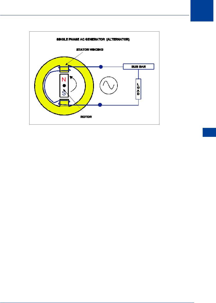
Figure 12.2 Single phase alternator
The output of this type of machine will rise to a maximum in one direction, then fall to zero, rise to a maximum in the other direction and then fall to zero again.
Polyphase Circuits
Polyphase or “multi-phase” alternators have two or more single phase windings symmetrically spaced around the stator.
The number of separate stator windings determines the number of phases present in the supply. The currents and voltages generated in this type of machine will have the same frequency but be out of phase with each other.
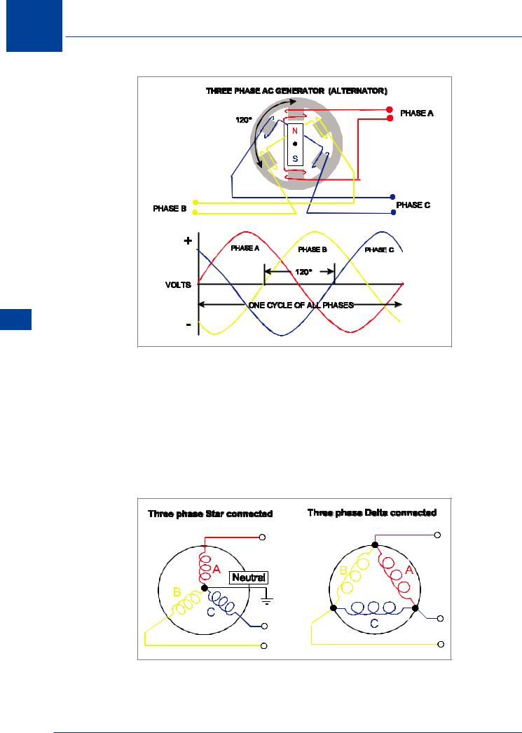
Corresponding values of voltage or current will be separated by an equal number of degrees. The most common polyphase alternator is the three phase alternator which has become the standard AC distribution system for aircraft. This is illustrated in Figure 12.3.
Note that the phase windings are mechanically arranged to be at 120° to each other in the sequence A, B, C so that the outputs are electrically separated by 120° as shown in the diagram. It can be seen that “A” phase reaches a peak going positive before “B” phase reaches a peak going positive before “C” phase reaches a peak going positive. This is the phase sequence ABC.
The peak values of the voltages induced in the three single phase windings of the three phase alternator shown in Figure 12.3 are 120° displaced from each other. The three phases are independent of each other.
AC Electrics - Alternators 12
189

12 AC Electrics -Alternators
Alternators - Electrics AC 12
Figure 12.3 Three phase alternator
The advantages of three phase systems are:
•They have a greater power / weight ratio.
•They are easier to connect in parallel.
Three Phase Alternator Connections
The outputs of a three phase alternator can be connected by either the “Star” or “Delta” method. These connections are shown in Figure 12.4.
Figure 12.4 Star and delta connection for three phase alternators
190

AC Electrics - Alternators 12
The Four Wire Star Connection
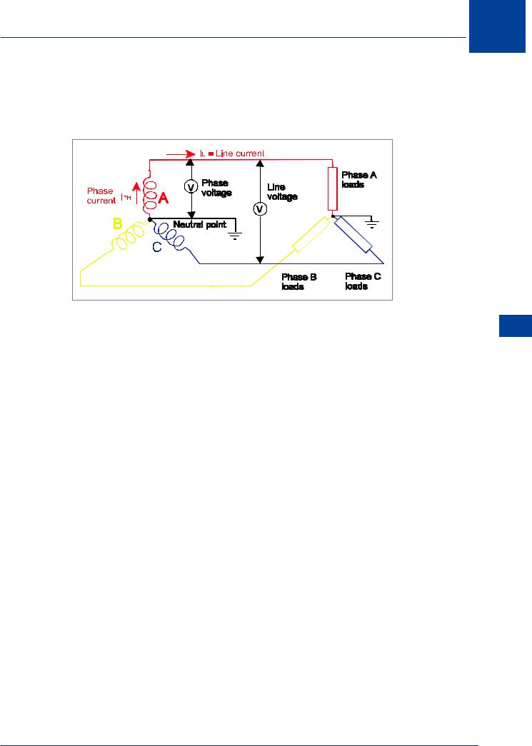
A star connected three phase alternator has the three phases joined at one end to form a fourth connection known as the neutral point. Refer to Figure 12.5.
Figure 12.5 Star connected alternator
The neutral point is normally grounded and used as the earth return in modern aircraft. The neutral line will carry any out of balance current. This means that if there is an earth fault on one phase, the neutral will carry an exceptionally high load.
This is the type of alternator that will be fitted to a typical aircraft distribution system because it can cope with different loads on each bus bar, the delta connection can not.
The connection at the opposite end of the phase from the neutral is called the line connection. A voltmeter measuring the potential difference between the neutral and the line lead would read phase voltage. A voltmeter measuring the potential difference between two line connections would read line voltage.
In this type of alternator the phase voltage and line voltage are different because phase voltage is measured across one phase whereas line voltage is measures across two phases and is the vector sum of the two.
Given one or the other of these values, the following formula will enable the student to establish the missing criterion:
Line Voltage = 1.73 × Phase Voltage
Note: (1.73 = √3)
The line voltage of a typical aircraft supply system would be 200 volts, and from the formula above it can be seen that the phase voltage would be:
200 |
or 115 volts |
|
1.73 |
||
|
To be more specific, a modern aircraft power supply would be 115 V/ 200 V/ 400 Hz/ 3 phase.
AC Electrics - Alternators 12
191

12 AC Electrics -Alternators
While the voltages of line and phase differ in the star connected system, because the windings form only one path for current flow between phases:
LINE CURRENT = PHASE CURRENT
Alternators - Electrics AC 12
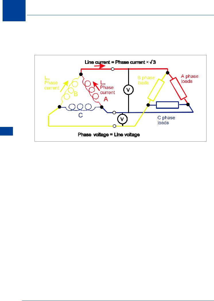
Figure 12.6 Delta connected alternator
Delta Connected Alternator
As can be seen from Figure 12.6, in this system the ends of the phases are joined together to form a closed mesh and the loads are connected in a similar fashion.
Logically, because the potential measured across the phase is measured between two lines, then:
LINE VOLTAGE IS PHASE VOLTAGE
BUT
LINE CURRENT = PHASE CURRENT × √3
This type of connection will not be used in a practical distribution system because it cannot cope with unbalanced loads as there is no neutral point. However, they may be used for specific purposes e.g. speed sensors or tacho generators.
Practical AC Generators
Rotating Armature alternators suffer from various disadvantages:
•The rotating coils are heavy and centrifugal forces are high.
•Efficient insulation of the rotating coils is difficult.
•The resistance across the brushes to the slip rings is high.
•The rotating coils are difficult to cool.
•They have a poor power to weight ratio.
192