

DC Electrics - Aircraft Electrical Power Systems |
|
8 |
|
||
|
|
|
Overvoltage Protection Unit
An overvoltage protection unit is fitted to protect against the output voltage of the generator rising dangerously high and causing damage to aircraft circuits due to overheating (W=I²R). It protects against voltage regulator failure.
The overvoltage protection circuit will automatically disconnect the field circuit if the voltage rises to typically 16.5 volts in a 14 volt system, thereby reducing the generator output to zero and safeguarding the system.
It may also open the generator cut-out to prevent reverse current flow.
Generator Cut-out or Reverse Current Relay
The generator cut-out permits the generator voltage to build up to a preset figure before its contacts close and put the generator on line. It will open to prevent the battery feeding current back into the generator when the generator voltage is below that of the battery voltage.
The contacts of a cut-out are closed by rising voltage and opened by reverse current. A cut-out is not fitted in an alternator system as the Rectifiers provide reverse current protection.
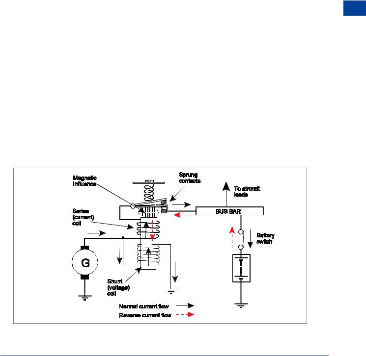
The reverse current cut-out relay shown below would be used with a DC generator. It may be an integral part of the voltage regulator or it may be a separate unit. Before the generator is started, the spring holds the contacts open. As the generator builds up voltage, that voltage is applied to the shunt (voltage) coil which has many turns of thin wire and is connected in parallel with the generator output. When the voltage has built up above the battery voltage the current through the voltage coil causes a magnetic influence to close the contacts and connect the generator to the bus bar. The current flows through the current coil, which has a few turns of thick wire, and through the contacts to the bus bar and the aircraft loads. The current flow through the current coil increases the magnetic effect and helps to keep the contacts closed against the spring.
DC Electrics - Aircraft Electrical Power Systems 8
Figure 8.3 Reverse current cut-out relay
123

8 |
|
DC Electrics - Aircraft Electrical Power Systems |
|
||
|
|
|
Systems Power Electrical Aircraft - Electrics DC 8
When the output voltage of the generator falls below battery voltage then current flow is reversed and current flows back toward the generator. The falling voltage of the generator causes the magnetic influence of the voltage coil to reduce and as the current flow through the current coil is reversed, it reverses the magnetic field produced by the current coil. This opposes the field produced by the voltage coil and allows the contacts to open by the spring, disconnecting the generator from the bus bar and preventing reverse current into the generator.
Rectifiers
The rectifiers in the alternator end frame convert AC to DC and permit the current to flow out from the alternator but not into it from the battery. They have a low resistance in the direction of current flow and a high resistance in the other direction.
Inverters
Static Inverter
Static inverters are solid state devices which covert DC to constant frequency AC. A typical input to a static inverter would be 18 - 30 volts DC and the output would be 115 volts AC at 400 hertz frequency. The internal circuitry of a static inverter contains standard electrical and electronic components such as oscillators, diodes, transistors, capacitors and transformers.
Rotary Inverter
Rotary inverters convert DC to AC by using a constant speed DC motor to drive an alternator thereby producing constant frequency AC.
The Generator Differential Cut-out
The generator differential cut-out is fitted in a multi-engine aircraft to prevent circulating currents between a generator which is already on line and one which is coming on line.
The on-coming generator cannot switch on line until its output voltage is 2% above the output voltage of the generator which is already on line. The 2% difference in potential is between the on-coming generator output and the battery bus bar.
Generator (or Alternator) Warning Light
The generator or alternator warning light indicates to the pilot that the generator or alternator voltage has fallen below battery voltage. Illumination of the light is usually associated with the generator cut-out position or a reverse current detector.
Generator (or Alternator) Master Switch
The master switch enables the pilot to electrically isolate the generator or alternator. Opening the master switch breaks the generator field circuit or the alternator exciter circuit and the electrical output falls to its residual level which is virtually zero.
124
DC Electrics - Aircraft Electrical Power Systems |
|
8 |
|
||
|
|
|
Monitoring Instruments
Instruments and warning lights must be provided for the pilot to monitor the aircraft DC or AC electrical system. The AC system is covered in the AC chapter, here we will examine typical meters and show their use in a DC system.
Ammeters and Voltmeters
Ammeters and voltmeters are provided in AC and DC systems and in most cases are of the moving coil type of instrument shown in the following diagram. The instrument consists of a permanent magnet with a soft iron core between the poles, inside which fits a former on a spindle which is free to rotate inside the magnetic field. A coil of wire is wound around the former and current is allowed to flow around the coil. Two hairsprings are fitted to restrain the movement of the coil; as the coil rotates one spring is wound up, the other unwound. The hairsprings allow the current to be fed into and out of the coil. The coil and former carry a pointer which is arranged to move over a scale as the coil rotates.
When current flows through the coil a magnetic field is created which interacts with the main field and causes the coil to rotate moving the indicator pointer across the scale until the torque is balanced by the hairspring. The greater the current flow through the coil, the greater will be the movement of the pointer. When the current flow reduces, the pointer will be returned to its ‘zero’ mark by the hairspring. So the deflection of the pointer is proportional to the current flowing through the coil, giving rise to an evenly divided scale.
The meter is likely to be housed inside a case made of soft iron to prevent stray magnetism affecting the indication.
To enable the range of the instrument to be extended a shunt (resistor of low resistance value) can be fitted in conjunction with this type of meter when used as an ammeter. When used as a voltmeter, a multiplier (resistor of high resistance value) is fitted. A shunt or multiplier will allow only a proportion of the total current to be allowed through the instrument therefore protecting the delicate mechanism but still allowing it to measure large values.
DC Electrics - Aircraft Electrical Power Systems 8
Figure 8.4 A moving coil instrument
125
8 |
|
DC Electrics - Aircraft Electrical Power Systems |
|
||
|
|
|
Systems Power Electrical Aircraft - Electrics DC 8
The number of indicating devices required and the types employed depends on the type of aircraft and the overall nature of its electrical installation.
One ammeter (or load meter) is normally provided for each possible source of power, and a single voltmeter with multiple selections for each DC system.
There are basically two types of ammeter:-
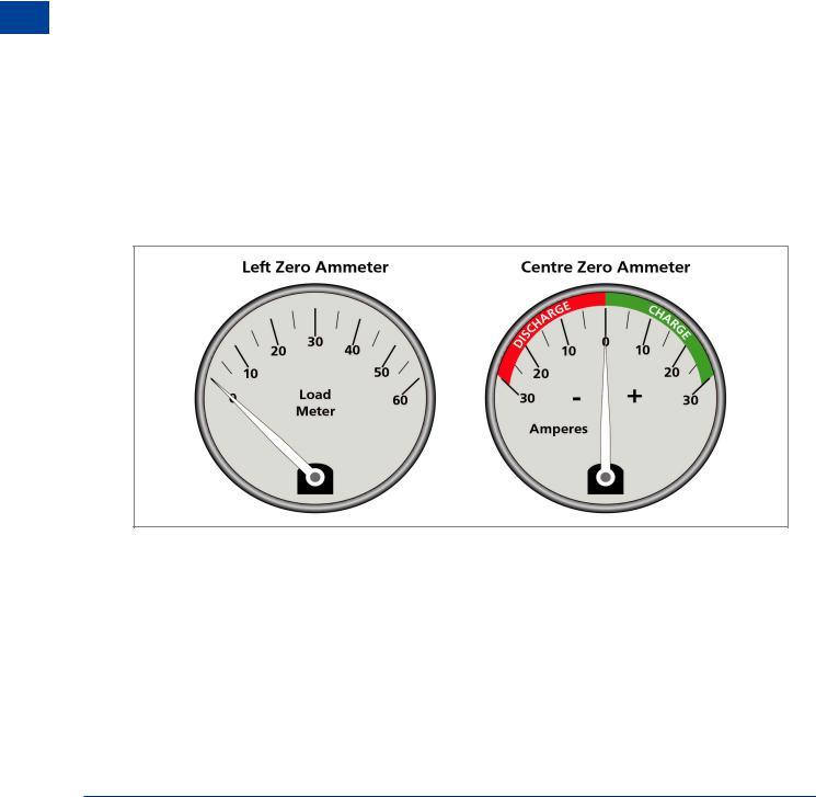
•The charge/discharge ammeter (or ‘centre zero’ ammeter) see Figure 8.5.
•The generator ammeter or load meter (‘left zero’ ammeter) see Figure 8.5.
The charge/discharge or centre zero type ammeter displays information about current flow into or out of the battery.
If the needle is to the right of zero, the alternator is working and supplying power to the electrical system and charging the battery.
If the needle is to the left of zero, then the battery is discharging, indicating that the alternator is not supplying power to the electrical system.
The load meter or left zero type of ammeter displays actual current draw (system demand) from the alternator.
If the load meter reads zero, then the alternator is not supplying power to the system, leaving the battery as the sole source of power in a single-engine system.
Figure 8.5 Simple ammeters
If an alternator fails in flight, all operating electrical equipment begins to deplete the battery. The pilot must therefore immediately assess the situation to determine what equipment is absolutely essential to the safety of flight at that moment and turn off everything else to conserve battery power.
This procedure is known as load shedding.
126