

|
DC Electrics - Generators and Alternators |
|
6 |
|||||||||
|
|
|
|
|
|
|
|
|
|
|
||
|
|
|
|
|
|
|
|
|
|
|
|
|
|
|
|
|
|
|
|
|
|
|
|
|
|
|
|
|
|
|
|
|
|
|
|
|
|
|
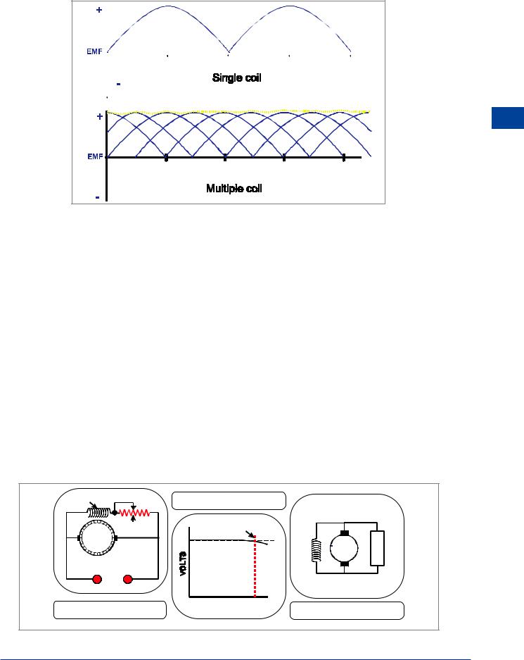
Figure 6.11 Single coil and multiple coil armature outputs
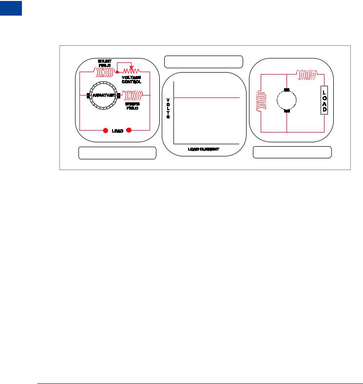
Characteristics of the Shunt Wound DC Generator
A shunt wound DC generator has its field winding connected in parallel (or shunt) with the armature. Therefore the current through the field coils is determined by the terminal voltage and the resistance of the field.
The shunt field windings have a large number of turns, and therefore require a relatively small current to produce the necessary field flux.
When a shunt generator is started, the build-up time for rated terminal voltage (the maximum voltage at which the generator can continuously supply its rated load current) at the brushes is very rapid since field current flows even though the external circuit is open.
Figure 6.12 shows a schematic diagram and characteristic curve for the shunt generator. It should be noted that over the normal operating range of ‘no load’ to ‘full load’, the drop in terminal voltage as the load current increases is relatively small The shunt generator is therefore used where a virtually constant voltage is desired, regardless of load changes.
The terminal voltage of a shunt generator can be controlled by a variable resistance connected in series with the shunt field coils.
SHUNT FIELD |
THE CHARACTERISTIC LOAD |
|
|
CURVE |
|
VOLTAGE |
RATED LOAD |
|
ARMATURE CONTROL |
L |
|
|
O |
|
|
A |
|
|
D |
|
LOAD |
|
|
A SHUNT WOUND DC |
LOAD CURRENT |
|
DIAGRAMMATIC VIEW |
||
GENERATOR |
||
|
Figure 6.12 Shunt wound generator
DC Electrics - Generators and Alternators 6
89
6 |
|
DC Electrics - Generators and Alternators |
|
||
|
|
|
Alternators and Generators - Electrics DC 6
A Compound Wound DC Generator
A compound wound generator is a generator with combined series and shunt windings. There are two sets of field coils, one in series with the armature, and one in parallel with the armature. One shunt coil and one series coil are always mounted on a common pole piece and are sometimes enclosed in a common covering.
Compound wound generators were designed to overcome the drop in terminal voltage which occurs in a shunt wound generator when the load is increased. This voltage drop is undesirable where constant voltage loads are used. By adding the series field, which increases the strength of the total magnetic field when the load current is increased, the voltage drop caused by the increased load current flowing through the resistance of the armature is overcome, and it is possible to obtain an almost constant voltage output.
|
THE CHARACTERISTIC LOAD |
|
|
CURVE |
|
COMPOUND WOUND DC |
DIAGRAMMATIC VIEW |
|
GENERATOR |
||
|
Figure 6.13 Compound wound generator
Flashing the Generator Field
The DC generator is normally self-excited due to the residual magnetism which remains in the field pole pieces when the machine is inactive or static. Self-excited means that because of the residual magnetism as soon as the generator is rotated there will be a voltage produced. Some of this voltage can be applied to the field coil to increase the magnetism and cause the voltage to increase further until it reaches its controlled value. An externally excited generator is one which has no residual magnetism and requires a battery to supply the field coil with current to start the generating process.
It will have been noted that magnetism can be lost, destroyed or reversed due to the passage of time, the effects of heat, exposure to an AC field, hammering or shock, and the application of a reversal of polarity. The loss of residual magnetism in a DC generator, which will prevent any build up in output voltage, can be corrected by momentarily passing a current through the field in the normal direction.
This procedure is known as “flashing the field”. In practice some aircraft might have a button or switch to allow this procedure to be carried out from the cockpit.
90
DC Electrics - Generators and Alternators |
|
6 |
|
||
|
|
|
Alternators
Most modern light aircraft use an alternator rather than a DC generator to provide constant voltage electricity for its electrical system because of the advantages an alternator has.
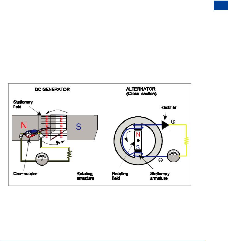
The alternator has a much better power to weight ratio, will produce a stable output at low RPM and does not suffer with the problems of a commutator as it uses a rectifier to convert AC to DC. The following table and diagram identify the constructional differences between the DC generator and the alternator.
|
|
|
|
6 |
|
|
|
|
|
|
|
DC GENERATOR |
ALTERNATOR |
|
|
Alternatorsand |
|
|
|
|
|
||
Stationary Field |
Rotating Field |
|
|
||
Rotating Armature |
Stationary Armature |
|
|
|
|
|
|
|
|
Generators- |
|
Converts AC to DC by means of a |
Converts AC to DC by means of a rectifier |
||||
commutator |
|
|
|
|
|
Suffers from arcing and sparking at the |
High load current |
taken |
from stationary |
Electrics |
|
commutator as the high load current |
armature eliminates arcing and sparking. |
||||
|
|||||
has to flow through the commutator |
Small field current |
only flows through slip |
DC |
||
and brushes |
rings. |
|
|
||
|
|
|
|||
|
|
|
|
|
|
LOAD |
LOAD |
Figure 6.14 Construction of a generator and alternator
91

6 |
|
DC Electrics - Generators and Alternators |
|
||
|
|
|
Alternators and Generators - Electrics DC 6
Voltage Control
The output voltage of a generator or alternator is dependent upon:
•The speed of rotation of the armature or field.
•The strength of the magnetic field.
•The number of turns in the armature.
•The size and shape of the turns in the armature.
Most light aircraft DC electrical systems operate at 14 volts and so all the equipment is designed to operate correctly when supplied with 14 volts. It is therefore necessary for the output of the generator or alternator to be controlled or regulated, to ensure that at all times it supplies 14 volts.
As can be seen from the points above, there are four factors which influence the output voltage of a generator or alternator.
The number and size and shape of the turns is a design factor and therefore the operator cannot alter them.
The generator or alternator is driven by a drive belt or an engine accessory gearbox and therefore the speed of rotation of the armature or field is linked to the speed of rotation of the engine. Controlling the output voltage by controlling the speed of the engine is not a practical solution.
Remember back to basic magnetism, the strength of the magnetic field produced by a coil of wire is proportional to the current flowing through the coil (an electromagnet).
The only practical method of controlling the output voltage of a generator is to control the strength of the magnetic field by controlling the current flow in a coil wound around the magnetic pole pieces (field coil or field winding). Control of the current flow is achieved by a voltage regulator.
A voltage regulator consists of:
•A variable resistance in series with the field coil. In older voltage regulators the variable resistance was achieved using a Carbon Pile. In modern voltage regulators it is achieved by employing an electronic solid state system of transistors, diodes and resistors. The net result is the same whichever is used.
•A control coil in parallel with the field coil and the armature. This is used to sense the generator output voltage and vary the resistance to control the current through the field coil, therefore controlling the voltage.
The voltage regulator senses the output voltage of the generator or alternator and adjusts the field current to maintain the correct output voltage irrespective of generator speed or electrical load
92