Laboratory work №3
.docxFederal Independent Educational Institution
«NATIONAL RESEARCH TOMSK POLYTECHNIC UNIVERSITY»
_____________________________________________________________
School of Energy & Power Engineering
Laboratory exercise No. 3
Capacitor and inductor in a circuit with sinusoidal current
Made by
Students of group 5A6B ________ _______
(signature) (date)
Checked by teacher ________ ______ M.V. Andreev
(signature) (date)
Tomsk – 2018
Objectives of the exercise:
To learn how to measure the parameters of а capacitor and inductor and to draw vector diagrams, to verify the Kirchhoff’s laws for a circuit with sinusoidal currents.
Theoretical Background:
In contrast to an ideal capacitor а real one has some losses of energy in the form of heat due to isolation imperfections. In analysis of electric circuits such а capacitor is represented as а equivalent circuit with elements connected in parallel. Parameters g and С of the equivalent circuit can be defined.
In case of parallel connection of R, L, and С elements according to Ohm’s and Kirchhoff’s laws one can write the following equation for the input current in complex representation:

where
 is the complex conductivity of the circuit, g is the active,
 is
the reactive, and у is the whole conductivity;
 is
the angle of phase shift between voltage and current,
 is
inductive conductivity and
 is the capacitive one. Voltage across the capacitor lags in phase
behind the current (the angle of phase shift is negative,
 .
.
А real inductance coil also has thermal losses in contrast to the ideal one. The equivalent circuit for such an inductor is usually represented as R and L elements connected in series. These parameters can be determined experimentally using the readings of devices and a vector diagram corresponding to the circuit.
In case of series connection of R, L, and С elements according to Ohm’s and Kirchhoff’s laws one can write in complex representation the following equation for the input voltage:

where
 is
the impedance of the circuit , R is the active and
 is
the reactive parts of impedance
 is
the angle of phase shift between voltage and current,
 is the inductive resistance and
 is the capacitive one.
Current
in the inductor lags in phase behind the voltage (the angle of phase
shift is positive,
 ).
).
Experimental Investigations:
Electrical circuits including an active - capacitive and active - inductive element which should be investigated in the laboratory exercise are drawn in Figs 1 and 2 correspondingly.
Table 1 – Circuit parameters
|
U |
f |
R1 |
C |
R2 |
L |
|
V |
Hz |
Ohm |
mkF |
Ohm |
mH |
|
5 |
2000 |
100 |
1 |
1000 |
100 |
 Fig.
1. Electrical
circuit including an active – capacitive element
 Fig.
2. Electrical
circuit including inductive element
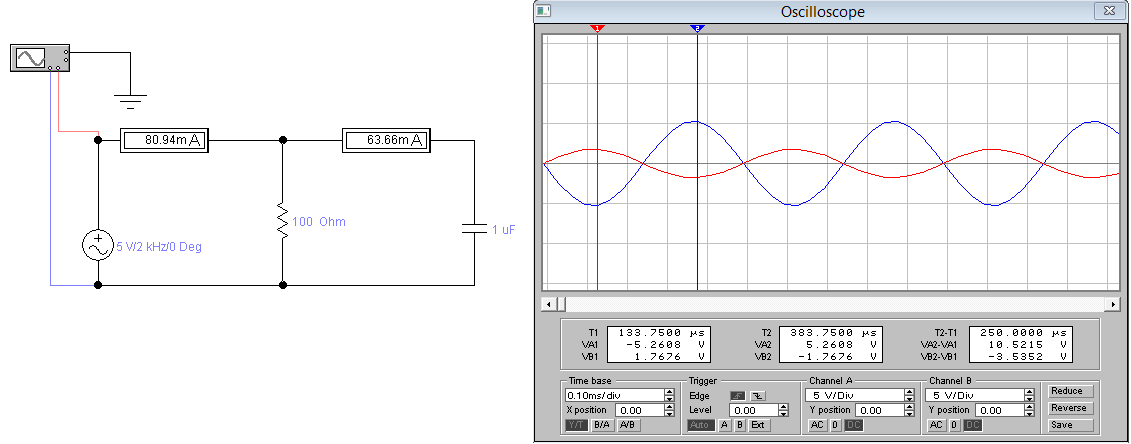
A) Investigation of an active-capacitive circuit.
1. Build the circuit shown in Fig.1 with parameters chosen according the variant of exercises (Table 1).
2. Set the frequency and the voltage of the generator and write down the parameters of the circuit to Table 2.
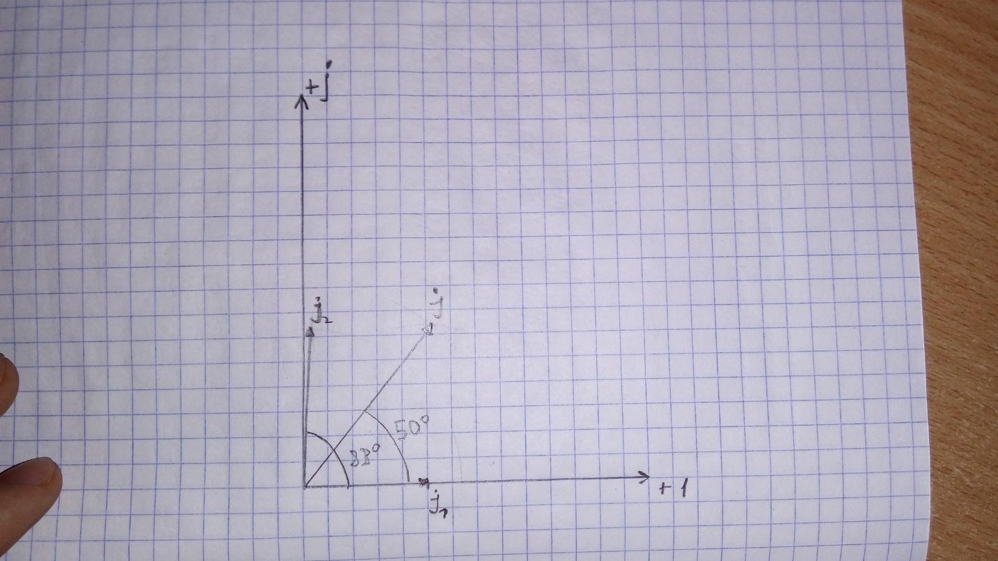
3. Calculate the current running in resistor R1, draw vectors of these current and voltage along the axis of real numbers in a vector diagram.
4. Write complex values of all current in Table 2 and calculate parameters g and C of the capacitor.
Table 2. Results of experiment
|
f
= 2000 Hz,
|
|||||||||||
|
Experiment |
Results of calculations |
||||||||||
|
U |
I |
I2 |
I1 |
|
g |
C |
|
|
|
|
|
|
V |
mA |
mA |
mA |
grad |
Sm |
mkF |
mA |
mA |
mA |
mA |
|
|
5 |
81 |
64 |
50 |
88 |
|
1,01 |
|
|
50 |
|
|
 Fig.
3. Investigated electrical circuit made in EWB
 Fig.
4. The oscillograms for input (red) and output (blue) voltages
Example of calculations:


 ;
;


Fig. 5 Vector diagram of currents
B) Investigation of an active-inductive circuit.
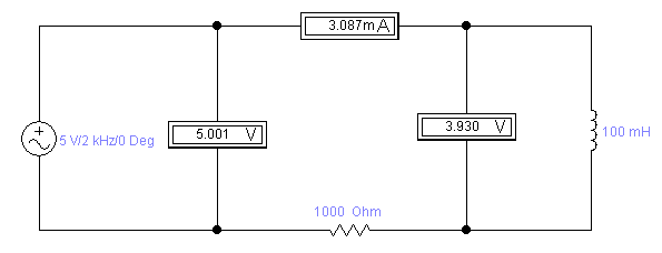
1. Assemble the circuit shown in Fig. 2 with parameters chosen according the variant of exercises.
2. Set the frequency and the voltage of the generator and write down the parameters of the circuit to Table 3.
3. Calculate the voltage across resistor R2 assuming that the initial phase angle of the input current equals zero. Draw vectors of these current and voltage along the axis of real numbers in a vector diagram.
4. Measure the angle between the current and voltage of the inductor in the diagram and calculate parameters of the inductor
5. Using the diagram measure the complex values of voltages.
Table 3. Results of experiment
|
F=2000
Hz;
|
|||||||||||
|
Experiment |
Results of calculations |
||||||||||
|
U |
I |
U1 |
U2 |
|
R |
L |
Ŭ |
Ŭ1 |
Ŭ2 |
Ŭ1+ Ŭ2 |
|
|
V |
mA |
V |
V |
grad |
Ohm |
mH |
V |
V |
V |
V |
|
|
5 |
3,1 |
3,9 |
2,85 |
89 |
21,9 |
100 |
|
|
|
|
|
 Fig.
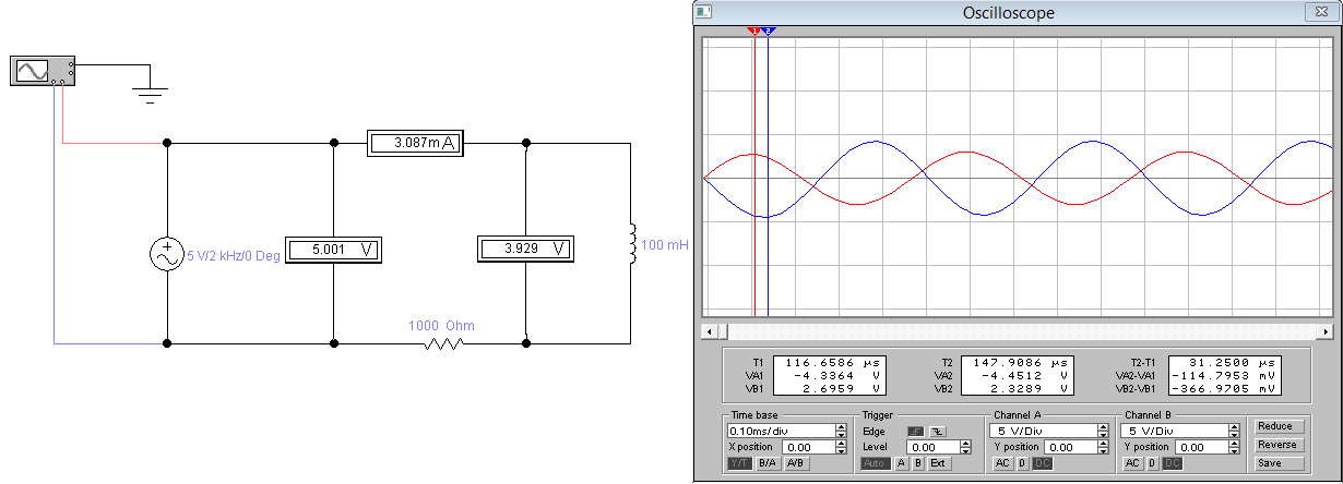
6. Investigated electrical circuit made in EWB
 Fig.
7. The
oscillograms for input (red) and output (blue) voltages
Example of calculations:


 Fig.
8. Vector diagram of voltages
Conclusion:
In this laboratory work we have constructed vector diagrams and determined by them complex values of currents and voltages. We verified the Kirchhoff’s laws for a circuit with sinusoidal currents. Also we have learned to determine parameters of the capacitor and inductor.
We
also calculated the angles between voltage and current in a circuit
with a capacitor and an inductor. Voltage across the capacitor lags
in phase behind the current (the angle of phase shift is negative,
 .
Current in the inductor lags in phase behind the voltage (the
angle of phase shift is positive,
 ).
).
The calculated angles coincided with theoretical values with a small error. In contrast to an ideal capacitor а real one has some losses of energy in the form of heat due to isolation imperfections, this explains the error.

 rad/s, R1
= 100 Ohms, C = 1 mkF


 rad/s; R2=1000 Ohms; L=100 mH


