

Антенны, СВЧ / OC / Должиков / Introduction to Smart Antennas_Balanis
.pdfSMART ANTENNAS 43
 USER
USER
 INTERFERER 2
INTERFERER 1
FIGURE 4.11: Adaptive array coverage: A representative depiction of a main lobe extending toward a user with nulls directed toward two co-channel interferers.
RCVR/Downconvert |
A/D |
w0 |
|
to Baseband |
|||
|
|
||
|
|
Output |
|
|
|
Signal |
|
RCVR/Downconvert |
A/D |
wM-1 |
|
to Baseband |
|||
|
|
||
|
|
Adaptive |
|
|
|
Algorithm |
|
|
|
DOA |
|
|
|
DSP |
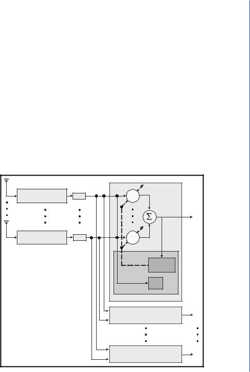
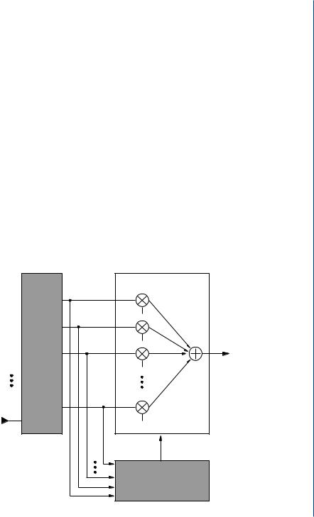
FIGURE 4.12: Functional block diagram of an adaptive array system.
After the system downconverts the received signals to baseband and digitizes them, it locates the SOI using the direction-of-arrival (DOA) algorithm, and it continuously tracks the SOI and SNOIs by dynamically changing the complex weights (amplitudes and phases of
44 INTRODUCTION TO SMART ANTENNAS
the antenna elements). Basically, the DOA computes the direction-of-arrival of all the signals by computing the time delays between the antenna elements, and afterward, the adaptive algorithm, using a cost function, computes the appropriate weights that result in an optimum radiation pattern. Because adaptive arrays are generally more digital processing intensive and require a complete RF portion of the transceiver behind each antenna element, they tend to be more expensive than switched-beam systems.
Adaptive arrays utilize sophisticated signal-processing algorithms to continuously distinguish between desired signals, multipath, and interfering signals, as well as calculate their Directions of Arrival (DOA). This approach updates its transmit strategy continuously based on changes in both the desired and interfering signal locations. A number of well-documented algorithms exist for estimating the DOA; for example, MUSIC, ESPRIT, or SAGE. These algorithms, which are discussed in Chapter 5, make use of a data matrix with the array snapshots collected within the coherence time of the channel. In essence, spatial processing dynamically creates a different sector for each user and conducts a frequency/channel allocation in an ongoing manner in real time. Fig. 4.13 illustrates the beams of a fully adaptive antenna system supporting two users.
In adaptive beamforming techniques, two main strategies are distinguished. The first one is based on the assumption that part of the desired signal is already known through the
User One
User Two
User One |
|
|
User Two |
|
|
|
|
|
|
|
|
|
|
|
|
|
|
|
|
|
|
|
|
|
|
|
|
|
|
(a) |
(b) |
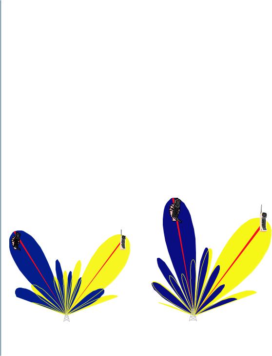
FIGURE 4.13: Fully adaptive spatial processing supporting two users on the same conventional channel simultaneously in the same cell [20].

SMART ANTENNAS 45
use of a training sequence. This known signal is then compared with what is received, and the weights are then adjusted to minimize the Mean Square Error (MSE) between the known and the received signals. In this way, the beampattern can be adjusted to null the interferers. This approach optimizes the signal-to-interference ratio (SIR), and is applicable to non-line-of-sight (NLOS) environments [93]. Since the weights are updated according to the incoming signals, not only the interference is reduced but the multipath fading is also mitigated. In the second one, the directions of arrivals from all sources transmitting signals to the array antenna are first identified. The complex weights are then adjusted to produce a maximum toward the desired angle and null toward interfering signals. This strategy may turn out to be deficient in practical scenarios where there are too many DOAs due to multipaths, and the algorithms are more likely to fail in properly detecting them. This is more likely to occur in NLOS environments where there are many local scatterers close to the users and the base station, thus resulting in a wider spread of the angle of arrival [93].
Another significant advantage of the adaptive antenna systems is the ability to share spectrum. Because of the accurate tracking and robust interference rejection capabilities, multiple users can share the same conventional channel within the same cell. System capacity increases through lower inter-cell frequency reuse patterns as well as intra-cell frequency reuse. Fig. 4.13 shows how adaptive antenna approach can be used to support simultaneously two users in the same cell on the same conventional channel.
In each of the two plots, the pattern on the left is used to communicate with the user on the left while the pattern on the right is used to talk with the user on the right. The drawn lines delineate the actual direction of each signal. Notice that as the signals travel down the indicated line toward the base station, the signal from the right user arrives at a null of the left pattern or minimum gain point and vice versa. As the users move, beam patterns are constantly updated to insure these positions. The plot at the bottom of the figure shows how the beam patterns have dynamically changed to insure maximum signal quality as one user moves toward the other. Fig. 4.14 summarizes the different smart antenna concepts and the functions of each one.
4.5SPACE DIVISION MULTIPLE ACCESS (SDMA)
A concept completely different from the previously described multiple access schemes, is the spatial division multiple access (SDMA) scheme. SDMA systems utilize techniques by which signals are distinguished at the BS based on their origin in space. They are usually used in conjunction with either FDMA, TDMA, or CDMA in order to provide the latter with the additional ability to explore the spatial properties of the signals [85]. SDMA is among the most sophisticated utilizations of smart antenna technology; its advanced spatial processing
46 INTRODUCTION TO SMART ANTENNAS
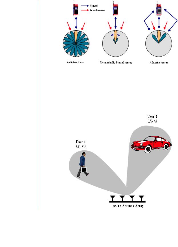
FIGURE 4.14: Different smart antenna concepts [20].
capability enables it to locate many users, creating different beams for each user, as shown in Fig. 4.15.
The SDMA scheme is based upon the concept that a signal arriving from a distant source reaches different antennas in an array at different times due to their spatial distribution [40]. This delay is utilized to differentiate one or more users in one area from those in another
FIGURE 4.15: SDMA concept [20].
SMART ANTENNAS 47
area. The scheme allows an effective transmission to take place in one cell without disturbing a simultaneous transmission in another cell. For example, conventional GSM/GPRS allows one user at a time to transmit or receive in a frequency band to the base station, where GSM/GPRS with SDMA allows multiple simultaneous transmissions in that same frequency band, multiplying the capacity of the system. CDMA system capacity is limited by its SIR, hence, with SDMA boosting the SIR in the system, more users will be allowed access by the network [94].
Filtering in the space domain can separate spectrally and temporally overlapping signals from multiple mobile units and it enables multiple users within the same radio cell to be accommodated on the same frequency and time slot [20], as illustrated in Fig. 4.15. This means that more than one user can be allocated to the same physical communication channel in the same cell simultaneously, with only separation in angle. This is accomplished by having N parallel beamformers at the base station operating independently, where each beamformer has its own adaptive beamforming algorithm to control its own set of weights and its own direction-of- arrival algorithm (DOA) to determine the time delay of each user’s signal [95, 96] as shown in Fig. 4.16. Each beamformer creates a maximum toward its desired user while nulling or
RCVR/Downconvert |
A/D |
w0 |
|
to Baseband |
|
||
|
|
|
|
|
|
|
y1 |
RCVR/Downconvert |
A/D |
wM-1 |
|
to Baseband |
|
||
|
|
Adaptive |
|
|
|
Algorithm |
|
|
|
DOA |
|
|
|
DSP |
|
|
|
Beamformer 1 |
|
|
|
Beamformer 2 |
y2 |
|
|
Beamformer N |
yN |
FIGURE 4.16: SDMA system block diagram [94, 95].
48 INTRODUCTION TO SMART ANTENNAS
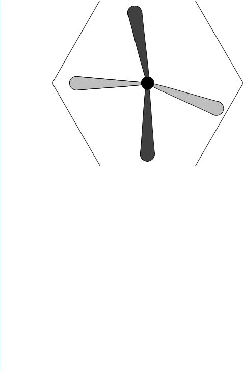
FIGURE 4.17: Channel reuse via angular separation [43].
attenuating the other users. This technology dramatically improves the interference suppression capability while greatly increases frequency reuse resulting in increased capacity and reduced infrastructure cost.
With SDMA, several mobiles can share the same frequency within a cell. Multiple signals arriving at the base station can be separated by the base station receiver as long as their angular separation is larger than the transmit/receive beamwidths [43]. This is shown in Fig. 4.17. The beams that have the same shading use the same frequency band. This technique is called channel reuse via angular separation.
Methods acting against fading are required for high data rate and highly reliable mobile communication systems [97]. A SDMA system is an effective measure to cope with fading, since it distinguishes radio signals in space or angular domain by using antenna directivity or beamforming according to the direction of arrival (DOA) of signals [9, 98].
4.6ARCHITECTURE OF A SMART ANTENNA SYSTEM
Any wireless system can be separated to its reception and transmission parts. Because of the advanced functions in a smart antennas system, there is a greater need for better co-operation between its reception and transmission parts.
SMART ANTENNAS 49
4.6.1Receiver
Fig. 4.18 shows schematically the block diagram of the reception part of a wireless system employing a smart antenna with M elements. In addition to the antenna itself, it contains a radio unit, a beam forming unit, and a signal processing unit [80].
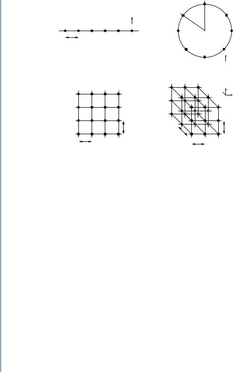
The number of elements in the array should be relatively low (the minimum required), in order to avoid unnecessarily high complexity in the signal processing unit. Array antennas can be one-, two-, and three-dimensional, depending on the dimension of space one wants to access. Fig. 4.19 shows different array geometries that can be applied in adaptive antennas implementations [80].
The first structure is used primarily for beamforming in the horizontal plane (azimuth) only. This will normally be sufficient for outdoor environments, at least in large cells. The first example (a) shows a one-dimensional linear array with uniform element spacing of x. Such a structure can perform beamforming in one plane within an angular sector. This is the most common structure due to its low complexity [20]. The second example (b) shows a circular array with uniform angular spacing between adjacent elements of ϕ = 2π/N, where N represents the number of elements. This structure can perform beamforming in any direction but, because of its symmetry, is more appropriate for azimuthal beamforming. The last two structures are
Antenna
(1) 
(2) 
(3) 
Radio unit
Beamforming network
w1
w2
w3
(M ) |
wM |
|
Signal processing unit
FIGURE 4.18: Reception part of a smart antenna [20].
50 INTRODUCTION TO SMART ANTENNAS
∆φ
y
 x
x
∆x
y
 x
x
(a) |
(b) |
z
y 
x
∆y |
∆z |
|
∆y |
∆x |
∆x |
(c) |
(d) |
FIGURE 4.19: Different uniform array geometries for smart antennas [20].
used to perform two-dimensional beamforming, i.e. in both azimuthal and elevation angles. Such specifications are usually desirable for indoor or dense urban environments. The front view of a two-dimensional rectangular array with horizontal element spacing of x and vertical element spacing of y is shown in (c). Beamforming in the entire space, within all angles, requires some sort of cubic or spherical structure (three-dimensional configuration). The fourth example (d) shows a cubic structure with element separations of x, y, and y, respectively, in each direction in space.
The radio unit consists of down-conversion chains and (complex) analog-to-digital conversion (A/D). There must be M down-conversion chains, one for each of the array elements. The received signals from the mobile units are combined into one, which is the input to the remaining part of the receiver (amplifier, channel decoding, etc.).
Based on the received signal, the signal-processing unit calculates the complex weights w1, w2, . . . , wM with which the received signal from each of the array elements is multiplied. These weights will determine the antenna pattern in the uplink direction. The estimate of the weights can be optimized using one of the two main criteria depending on the application and complexity:
a.Maximization of the power of the received signal from the desired user (e.g., switchedbeam or phased array), or

SMART ANTENNAS 51
b.Maximization of the SIR by suppressing the signal received from the interference sources (adaptive array).
In theory, with M antenna elements M − 1 sources of interference can be “nulled out”, but this number will normally be lower due to the multipath propagation environment.
The method for calculating the weights differs depending on the type of optimization criterion. When the switched-beam (SB) is used, the receiver will test all the predefined weight vectors (corresponding to the beam set) and choose the best one giving the strongest received signal level. If the phased array approach (PA) is used, which consists of directing a maximum gain beam toward the strongest signal component, the weights are calculated after the direction-of-arrival (DOA) is first estimated. A number of well-documented methods exist for estimating the DOA and will be presented in Chapter 5. In the adaptive array approach (AA), where maximization of SIR is needed, the optimum weight vector (of dimension M) wo pt can be computed using a number of algorithms such as optimum combining and others that will follow.
When the beam forming is done digitally (after A/D), the beam forming and signal processing units can normally be integrated in the same unit (Digital Signal Processor, DSP). The separation in Fig. 4.18 is done to clarify the functionality. The beam forming can be performed in either at radio frequency (RF) or intermediate frequency (IF).
4.6.2Transmitter
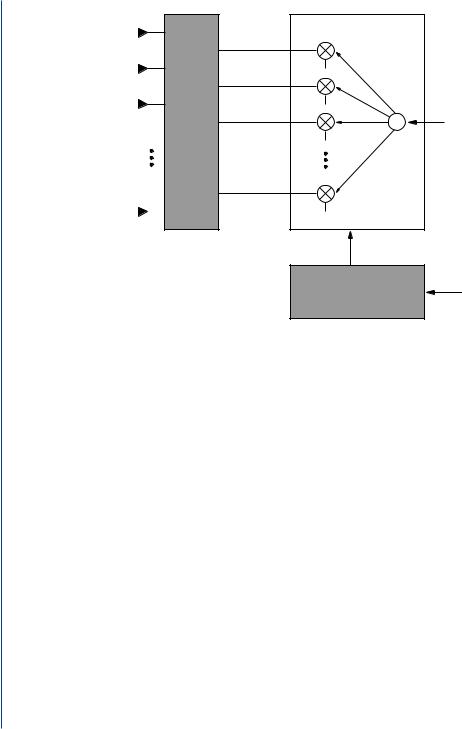
Normally the adaptive process is applied to the uplink/reception only (from the mobile to the base station). In that case the mobile unit consumes less transmission power, and the operational time of the battery is extended. However, the benefits of adaptation are very limited, if no beamforming is applied in the downlink transmission (from the base station to the mobile). In principle, the methods used in the uplink can be carried over the downlink [99]. The transmission part of a smart antenna system is schematically similar to its reception part as shown in Fig. 4.20.
The signal is split into N branches, which are weighted by the complex weights w1, w2, . . . , wN in the lobe-forming unit. The signal-processing unit calculates suitably the weights, which form the radiation pattern in the downlink direction. The radio unit consists of D/A converters and the up-converter chains. In practice, some components, such as the antennas themselves and the DSP, will be the same as in reception. The principal difference between uplink and downlink is that since there are no smart antennas applied to the user terminals (mobile stations), there is only limited knowledge of the Channel State Information (CSI) available. Therefore, the optimum beamforming in downlink is difficult and the same performance as the uplink cannot be achieved.
52 INTRODUCTION TO SMART ANTENNAS
Antenna |
|
Beamforming network |
|
(1) |
|
|
|
(2) |
|
w1 |
|
|
|
Splitter |
|
(3) |
unit |
w2 |
|
|
|
||
Radio |
|
|
|
|
w3 |
|
|
|
|
|
|
(N ) |
|
wN |
|
|
Signal processing unit
FIGURE 4.20: Transmission part of a smart antenna [20].
DOA from uplink
Typically there exist two approaches to overcome this impairment. The first one is to devise methods that do not require any CSI, but with somewhat limited performance gain. The second one is the assumption of directional reciprocity, i.e., the direction from which the signal is arrived on the uplink is closely related to the downlink CSI. This assumption has been strengthened by recent experimental results.
Physically an adaptive antenna looks very much like an ordinary antenna but has built-in electronics and control software. It cooperates with the receiver’s adaptive control system in real time. It may also communicate interactively with the cellular radio network control system.
Smart antenna techniques have only recently been considered for implementation in land mobile stations and vehicle installed units because of their high system complexity and large power consumption [69, 100]. A number of smart antenna arrays for base station applications have already been proposed in [12, 13, 27]. However, only limited efforts have been yet considered for developing adaptive antenna array receivers suitable for handsets [101–103]. In fact, there exist several practical difficulties with the implementation of such a solution at the handset level [104]. These are:
i.The space on the handset device is limited and does not allow the implementation of an antenna array with number of elements necessary enough for efficient spatial