

Антенны, СВЧ / OC / Должиков / Introduction to Smart Antennas_Balanis
.pdf33
C H A P T E R 4
Smart Antennas
4.1INTRODUCTION
Many refer to smart antenna systems as smart antennas, but in reality antennas by themselves are not smart. It is the digital signal processing capability, along with the antennas, which make the system smart. Although it may seem that smart antenna systems are a new technology, the fundamental principles upon which they are based are not new. In fact, in the 1970s and 1980s two special issues of the IEEE Transactions on Antennas and Propagation were devoted to adaptive antenna arrays and associated signal processing techniques [78, 79]. The use of adaptive antennas in communication systems initially attracted interest in military applications [27]. Particularly, the techniques have been used for many years in electronic warfare (EWF) as countermeasures to electronic jamming. In military radar systems, similar techniques were already used during World War II [80]. However, it is only because of todays advancement in powerful low-cost digital signal processors, general-purpose processors and ASICs (Application Specific Integrated Circuits), as well as innovative software-based signal processing techniques (algorithms), that smart antenna systems are gradually becoming commercially available [17, 59].
4.2NEED FOR SMART ANTENNAS
Wireless communication systems, as opposed to their wireline counterparts, pose some unique challenges [42]:
i.the limited allocated spectrum results in a limit on capacity
ii.the radio propagation environment and the mobility of users give rise to signal fading and spreading in time, space and frequency
iii.the limited battery life at the mobile device poses power constraints
In addition, cellular wireless communication systems have to cope with interference due to frequency reuse. Research efforts investigating effective technologies to mitigate such effects have been going on for the past twenty five years, as wireless communications are experiencing rapid growth [42]. Among these methods are multiple access schemes, channel coding and
34 INTRODUCTION TO SMART ANTENNAS
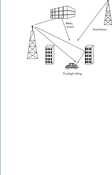
FIGURE 4.1: Wireless systems impairments [81].
equalization and smart antenna employment. Fig. 4.1 summarizes the wireless communication systems impairments that smart antennas are challenged to combat.
An antenna in a telecommunications system is the port through which radio frequency (RF) energy is coupled from the transmitter to the outside world for transmission purposes, and in reverse, to the receiver from the outside world for reception purposes [57, 59]. To date, antennas have been the most neglected of all the components in personal communications systems. Yet, the manner in which radio frequency energy is distributed into and collected from space has a profound influence upon the efficient use of spectrum, the cost of establishing new personal communications networks and the service quality provided by those networks [20]. The commercial adoption of smart antenna techniques is a great promise to the solution of the aforementioned wireless communications’ impairments.
4.3OVERVIEW
The basic idea on which smart antenna systems were developed is most often introduced with a simple intuitive example that correlates their operation with that of the human auditory system. A person is able to determine the Direction of Arrival (DoA) of a sound by utilizing a three-stage process:

SMART ANTENNAS 35
FIGURE 4.2: Human auditory function [17].
One’s ears act as acoustic sensors and receive the signal.
Because of the separation between the ears, each ear receives the signal with a different time delay.
The human brain, a specialized signal processor, does a large number of calculations to correlate information and compute the location of the received sound.
To better provide an insight of how a smart antenna system works, let us imagine two persons carrying on a conversation inside an isolated room as illustrated in Fig. 4.2. The listener among the two persons is capable of determining the location of the speaker as he moves about the room because the voice of the speaker arrives at each acoustic sensor, the ear, at a different time. The human “signal processor,” the brain, computes the direction of the speaker from the time differences or delays received by the two ears. Afterward, the brain adds the strength of the signals from each ear so as to focus on the sound of the computed direction.
Utilizing a similar process, the human brain is capable of distinguishing between multiple signals that have different directions of arrival. Thus, if additional speakers join the conversation, the brain is able to enhance the received signal from the speaker of interest and tune out unwanted interferers. Therefore, the listener has the ability to distinguish one person’s voice, from among many people talking simultaneously, and concentrate on one conversation at a time. In this way, any unwanted interference is attenuated. Conversely, the listener can respond back to the same direction of the desired speaker by orienting his/her transmitter, his/her mouth, toward the speaker.
Electrical smart antenna systems work the same way using two antennas instead of two ears, and a digital signal processor instead of the brain as seen in Fig. 4.3. Thus, based on the

36 INTRODUCTION TO SMART ANTENNAS
w1 w2
+ |
DSP |
FIGURE 4.3: A two-element electrical smart antenna.
time delays due to the impinging signals onto the antenna elements, the digital signal processor computes the direction-of-arrival (DOA) of the signal-of-interest (SOI), and then it adjusts the excitations (gains and phases of the signals) to produce a radiation pattern that focuses on the SOI while tuning out any interferers or signals-not-of-interest (SNOI).
Transferring the same idea to mobile communication systems, the base station plays the role of the listener, and the active cellular telephones simulate the role of the several sounds heard by human ears. The principle of a smart antenna system is illustrated in Fig. 4.4.
A digital signal processor located at the base station works in conjunction with the antenna array and is responsible for adjusting various system parameters to filter out any interferers or signals-not-of-interest (SNOI) while enhancing desired communication or signals-of-interest (SOI). Thus, the system forms the radiation pattern in an adaptive manner, responding dynamically to the signal environment and its alterations. The principle of beamforming is essentially to weight the transmit signals in such a way that the receiver obtains a constructive superposition of different signal parts. Note that some knowledge of the transmission channel at the transmitter is necessary in order for beamforming to be feasible [82]. A comprehensive overview of beamforming techniques is given in [83]. Fig. 4.5 illustrates the general idea of adaptive beamforming.

SMART ANTENNAS 37
control
RF in/out |
Steerable |
|
lobe |
||
|
Antenna
element
To/from radio subsystem
“intelligence”
FIGURE 4.4: Principle of a smart antenna system [80].
4.4SMART ANTENNA CONFIGURATIONS
Basically, there are two major configurations of smart antennas:
Switched-Beam: A finite number of fixed, predefined patterns or combining strategies (sectors).
Adaptive Array: A theoretically infinite number of patterns (scenario-based) that are adjusted in real time according to the spatial changes of SOIs and SNOIs.
In the presence of a low level interference, both types of smart antennas provide significant gains over the conventional sectorized systems. However, when a high level interference is present, the interference rejection capability of the adaptive systems provides significantly more coverage than either the conventional or switched beam system [4]. Fig. 4.6 illustrates the relative coverage area for conventional sectorized, switched-beam, and adaptive antenna systems.
Both types of smart antenna systems provide significant gains over conventional sectorized systems. The low level of interference environment on the left represents a new wireless system with lower penetration levels. However the environment with a significant level of interference on the right represents either a wireless system with more users or one using more aggressive frequency reuse patterns. In this scenario, the interference rejection capability of the adaptive system provides significantly more coverage than either the conventional or switched beam systems [4].

38 INTRODUCTION TO SMART ANTENNAS
(a)
SOI
SNOI |
|
SNOI |
|
|
|
(b)
FIGURE 4.5: Adaptation procedure: (a) Calculation of the beamformer weights [20] and (b) Beamformed antenna amplitude pattern to enhance SOI and suppress SNOIs.
Now, let us assume that a signal of interest and two co-channel interferers arrive at the base station of a communications system employing smart antennas. Fig. 4.7 illustrates the beam patterns that each configuration may form to adapt to this scenario.
The switched-beam system is shown on the left while the adaptive system is shown on the right. The light lines indicate the signal of interest while the dark lines display the direction of the co-channel interfering signals. Both systems direct the lobe with the greatest intensity in the general direction of the signal of interest. However, switched fixed beams achieve coarser pattern

SMART ANTENNAS 39
Adaptive |
Adaptive |
|
 Switched Beam
Switched Beam
Conventional |
|
|
Sectorization |
|
|
Low |
Conventional |
Significant |
Interference |
Sectorization |
Interference |
|
||
Environment |
|
Environment |
FIGURE 4.6: Coverage patterns for switched beam and adaptive array antennas [20].
Switched strategy |
Adaptive strategy |
FIGURE 4.7: Beamforming lobes and nulls that Switched-Beam (left) and Adaptive Array (right) systems might choose for identical user signals (light line) and co-channel interferers (dark lines) [20].
control than adaptive arrays [84]. The adaptive system chooses a more accurate placement, thus providing greater signal enhancement. Similarly, the interfering signals arrive at places of lower intensity outside the main lobe, but again the adaptive system places these signals at the lowest possible gain points. The adaptive array concept ideally ensures that the main signal receives maximum enhancement while the interfering signals receive maximum suppression.
4.4.1Switched-Beam Antennas
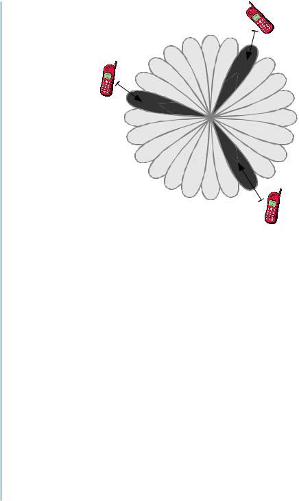
A switched-beam system is the simplest smart antenna technique. It forms multiple fixed beams with heightened sensitivity in particular directions. Such an antenna system detects signal strength, chooses from one of several predetermined fixed beams, and switches from one beam to another as the cellular phone moves throughout the sector, as illustrated in Fig. 4.8.
40 INTRODUCTION TO SMART ANTENNAS
FIGURE 4.8: Switched-beam coverage pattern [85].
The switched-beam, which is based on a basic switching function, can select the beam that gives the strongest received signal. By changing the phase differences of the signals used to feed the antenna elements or received from them, the main beam can be driven in different directions throughout space. Instead of shaping the directional antenna pattern, the switched-beam systems combine the outputs of multiple antennas in such a way as to form narrow sectorized (directional) beams with more spatial selectivity that can be achieved with conventional, single-element approaches. Other sources in the literature [86] define this concept as phased array or multibeam antenna. Such a configuration consists of either a number of fixed beams with one beam turned on toward the desired signal or a single beam (formed by phase adjustment only) that is steered toward the desired signal.
A more generalized to the Switched-Lobe concept is the Dynamical Phased Array (DPA). In this concept, a direction of arrival (DOA) algorithm is embedded in the system [20]. The DOA is first estimated and then different parameters in the system are adjusted in accordance with the desired steering angle. In this way the received power is maximized but with the trade-off of more complicated antenna designs.
The elements used in these arrays must be connected to the sources and/or receivers by feed networks. One of the most widely-known multiple beamforming networks is the Butler matrix [87, 88]. It is a linear, passive feeding, N × N network with beam steering capabilities

SMART ANTENNAS 41
1 |
2 |
3 |
4 |
- π |
|
|
π |
Fixed |
4 |
|
|
4 |
|
|
|
|
|
phase |
|
|
|
|
shifters |
|
|
|
|
3-dB |
1R |
2L |
2R |
1L |
coupler |
|
FIGURE 4.9: A schematic diagram of a 4 × 4 Butler matrix [90].
for phased array antennas with N outputs connected to antenna elements and N inputs or beam ports. The Butler matrix performs a spatial fast Fourier transform and provides N orthogonal beams, where N should be an integer power of 2 (i.e. N = 2n, n Z+) [89]. These beams are linear independent combinations of the array element patterns. A Butler matrix-fed array can cover a sector of up to 360◦ depending on element patterns and spacing. Each beam can be used by a dedicated transmitter and/or receiver and the appropriate beam can be selected using an RF switch. A Butler matrix can also be used to steer the beam of a circular array by exciting the Butler matrix beam ports with amplitude and phase weighted inputs followed by a variable uniform phase taper [89]. The only required transmit/receive chain combines alternate rows of hybrid junctions (or directional couplers) and fixed phase shifters [90]. Fig. 4.9 shows a schematic diagram of a 4 × 4 Butler matrix.
A total of (N/2) × log2 N hybrids and (N/2) × log2(N − 1) fixed phase shifters are required to form the network. The hybrids can be either 90◦ or 180◦ 3 dB hybrids, depending on if the beams are to be symmetrical distributed about the broadside or whether one of the beams is to be in the broadside direction [91]. A Butler matrix serves two functions:
i.distribution of RF signals to radiating antenna elements and
ii.orthogonal beam forming and beam steering.
By connecting a Butler matrix between an antenna array and an RF switch, multiple beamforming can be achieved by exciting two or more beam ports with RF signals at the same time. A signal introduced at an input port will produce equal excitations at all output ports with a progressive phase between them, resulting in a beam radiated at a certain angle in space. A signal at another input port will form a beam in another direction, achieving beam steering. Referring to Fig. 4.10, if ports 1R and 4L are excited at the same time with RF signals of equal amplitude

42 INTRODUCTION TO SMART ANTENNAS
1L |
1R |
2L |
2R |
3L |
3R |
4L |
4R |
FIGURE 4.10: 8 orthogonal beams formed by an 8 × 8 Butler matrix [90].
and phase, beams 2R and 3L will radiate simultaneously. Although multiple beamforming is possible, there is a limitation. Two adjacent beams cannot be formed simultaneously as they will add to produce a single beam [92].
4.4.2Adaptive Antenna Approach
The adaptive antenna systems approach communication between a user and a base station in a different way by adding the dimension of space. By adjusting to the RF environment as it changes (or the spatial origin of signals), adaptive antenna technology can dynamically alter the signal patterns to optimize the performance of the wireless system. Adaptive array systems [78, 79] provide more degrees of freedom since they have the ability to adapt in real time the radiation pattern to the RF signal environment; in other words, they can direct the main beam toward the pilot signal or SOI while suppressing the antenna pattern in the direction of the interferers or SNOIs. To put it simply, adaptive array systems can customize an appropriate radiation pattern for each individual user. Fig. 4.11 illustrates the general idea of an adaptive antenna system.
The adaptive concept is far superior to the performance of a switched-beam system, as it is shown in Fig. 4.6. Also, it shows that switched-beam system not only may not be able to place the desired signal at the maximum of the main lobe, but also it exhibits inability to fully reject the interferers. Because of the ability to control the overall radiation pattern in a greater coverage area for each cell site, as illustrated in Fig. 4.7, adaptive array systems can provide great increase in capacity. Adaptive array systems can locate and track signals (users and interferers) and dynamically adjust the antenna pattern to enhance reception while minimizing interference using signal processing algorithms. A functional block diagram of the digital signal processing part of an adaptive array antenna system is shown in Fig. 4.12.